LLB09010B1LLB09010B1 TRANSCEIVER MODULE
Aclara Technologies LLC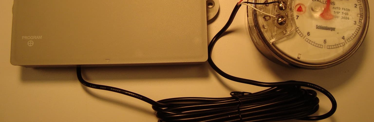
Click to zoom
Application Details
- Equipment Class
- TNB - Licensed Non-Broadcast Station Transmitter
- Date of Grant
- Mar 02, 2014
- Application Purpose
- Original Equipment
- Date of Application
- Mar 02, 2014
- Equipment Note
- LLB09010B1 TRANSCEIVER MODULE
- Frequency Range
- 467.73750000 - 470.00000000
- Company
- Aclara Technologies LLC
- Country
- United States
Documents & Files
Document Text
Text extracted from the exhibit documents filed with the FCC. Open a document above to read the original.
Cover Letter(s)
Page 1 of 1 Test Lab Attestation Letter Date of Test: 06 Feb 2014 – 01 Feb 2014 Applicant Name: Aclara RF Systems FCC Id: LLB09010B1 Name of Engineer Performing Test: David Foerstner & Steven Hoke Statement of Compliance: Product Safety Engineering declares that this Unit has been tested in accordance with the test method identified in this test report and that we observed it being tested. It also declares that the Unit complies with the relevant limits. All instrumentation and accessories used to test this unit for compliance to the indicated test method are calibrated regularly in accordance with ISO 17025:2005 requirements by laboratories accredited by A2LA, NVLAP, or ACLAS for the measurement parameters. The measurements were made at: Product Safety Engineering 12966 Bellamy Bros. Blvd., Dade City, FL 33525 Test Lab Witness- Steven Hoke Signature of Test Lab Witness: Full Name, Typed: Steven Hoke Title of Witness: EMC Site Manager Email Address: [email protected] Phone No.: 352-588-2209 X104 M:\Master Documents\Test Lab_Authorization LetterRev 120703.doc
ID Label/Location Info
1.40 .39 NOTES: 1) MATERIAL: 4 MIL PRINTABLE POLYESTER/HIGH STRENGTH ACRYLIC SOLVENT ADHESIVE (AVERY) FASSON SPEC #72828 OR EQUIVALENT 2) BACKGROUND COLOR TO BE PANTONE 429 GRAY 3) TEXT TO BE MINIMUM OF 0.08" HIGH 4) TEXT COLOR TO BE BLACK 5) FCC / IC ID INFORMATION MAY BE INCLUDED IN BARCODE, BUT IS NOT REQUIRED D C B A A B C D SCALE: SIZE CAD FILE: DWG. NO. B SHEET1OF1 REV. DATE APPROVALS DRAWN CHECKED RESP ENG MFG ENG QUAL ENG UNLESS OTHERWISE SPECIFIED DIMENSIONS ARE IN INCHES TOLERANCES ARE: FRACTIONS DECIMALS ANGLES MATERIAL FINISH DO NOT SCALE DRAWING APPLICATION USED ONNEXT ASSY 123 456 7 8 8 7 6 5 4 32 1 REVISIONS REV. DATE APPROVED SEE NOTES .XX=.010 .XXX= .005 .XXXX= .0005 1/2 1/64 WAD2/6/14 091-LLB09010B1 4:1 091-LLB09010B1 A 2/6/14 DESCRIPTION A BY WAD INITIAL RELEASE LABEL, FCC, MTU THE WRITTEN PERMISSION OF ACLARA RF SYSTEMS INC. IS PROHIBITED. ACLARA RF SYSTEMS INC. ANY REPRODUCTION IN PART OR WHOLE WITHOUT THE INFORMATION CONTAINED IN THIS DRAWING IS THE SOLE PROPERTY OF (C) 2011 ACLARA RF SYSTEMS INC. ALL RIGHTS RESERVED. PROPRIETARY AND CONFIDENTIAL.
Parts List/Tune Up Info
ACLARA Technologies LLC 30400 Solon Road. Solon, OH 44139 440-528-7200 Feb 18 th 2014 Field Calibration and Tune-Up Procedure FCC ID: LLB09010B1 Aclara Technologies low power RF devices have passed through extensive testing and calibration Procedures while in the factory. We test the LLB09010B1 units in production at the customer operating frequency of 467.3125MHz and measure the conducted power at 26 dBm with +/- 1.5 dB tolerance. The transmit power level is fixed and is set using a software setting in the Transceiver. These low power RF devices are shipped to the customer in the sealed enclosures. Therefore, no additional calibration, tuning is required in the field. No adjustments can be made in the field, without breaking the factory sealed enclosure. Sincerely, Siva Jambulingam Principal RF Engineer 440-528-7200 [email protected]
Test Report
12955 Bellamy Brothers Blvd. Dade City, FL 33525 352-588-2209 TEST REPO RT Project Number 13445 Report Issue Date: 02/11/2014 Applicant: Aclara RF Systems 30400 Solon Road Solon, Ohio 44139 Product: Model - 101-2009-010B1 Description: Water Meter Transmitting Unit FCC ID: LLB09010B1 IC ID: 4546A-09010B1 Test dates: 02/06/2014 – 02/11/2014 Receive Date: 02/06/2014 For the purpose of demonstrating compliance with FCC Part 90 & Industry Canada RSS-119 & RSS:GEN Prepared by: Steven E. Hoke - EMC Site Manager FCC Registered Test Site Number: 160606 Industry Canada Registered Test Site Number: IC 2087A-1 This report may only be reproduced in full without written permission from Product Safety Engineering, Inc. Aclara RF Systems FCC ID:LLB09010B1 IC ID:4546A-09010B1Page 1 of 11 Table of Contents Page 2 Table of contents Page 3-4 Test procedures Page 5 Equipment Calibration Page 6 Power Output and Spurious Emissions Page 7 Occupied Bandwidth Test Data Page 8 Frequency Stability vs. Temperature Page 9 Frequency Stability vs. Supply Voltage Page 10 Transient Stability (Separate report) Page 11 ERP Setup Photos Aclara RF Systems FCC ID:LLB09010B1 IC ID:4546A-09010B1 Page 2 of 11 Test Procedures EUT description: The Model - 101-2009-010B1 transceiver is designed to provide remote meter reading capability. The transceiver is attached to the meter with wiring. The transmitter provides a very short intermittent RF transmission to provide a remote reading of the meter. A microprocessor provides timing, control and data processing functions. The built in antenna is inaccessible to the user and no provision is made for an external antenna. The receiver can be used to request a meter reading or other options available in the system. Pow er Output: The EUT operates in the frequency range of (450 - 470) MHz. The first step in the measurement process was to measure the field strength of the f undamental frequency at the lowest, highest and middle operating frequency. These measurements are made in both the vertical and horizontal polarity. The maximum field strength is reported by raising and lowering the measuring antenna height between (1-4) meters and by rotating the EUT (360) degrees. The measurement distance is (3) meters. Measurements made per ANSI/TIA-603-C-2004. The field strength measurements continue as described above for up to the tenth harmonic of each f undamental frequency. Once the field strength of each signal is recorded, the EUT is replaced with a substitution antenna and signal generator. The substitution antenna is placed at the same height as the EUT had been. The combination of antenna and signal generator is then adjusted to reproduce the recorded field strength at each frequency. The ERP is then calculated by the following: ERP = PG - CL + ANT ERP = Effective Radiated Power (dBm) PG = Signal Generator Output (dBm) CL = Cable loss (dB) ANT = antenna gain (dBd) dBd = (antenna gain dBi) - (2.2 dB) Occupied Bandw idth: The occupied bandwidth was measured with the EUT set to the middle of the operating frequency range. The emissions mask used was that specified in Part 90.210 (d). Radiated Spurious Emissions: The radiated spurious emissions measurements were measured with the EUT set to low, medium and high transmit frequencies. Based upon the low output power of this device, all spurious and harmonic signals are limited to (-20) dBm. This is based upon the calculation stated in 90.210(d)(3). The field strength of the spurious emissions were measured in the same manner as the power output measurements and then the substitution method was used to establish the power level expressed in dBm. Measurements made per ANSI/TIA-603-C-2004. Frequency Stability vs. Supply Voltage: One of the internal batteries was disconnected and replaced with an external variable power supply. The frequency was measured at the normal battery voltage of (7.20) VDC and again with the external power supply adjusted to an (85%) level or (6.12) volts. This was repeated with the external DC voltage adjusted to (8.28) VDC. The maximum allowed deviation is (2.5) ppm or (1,150) Hz at (460) MHz. Aclara RF Systems FCC ID:LLB09010B1 IC ID:4546A-09010B1 Page 3 of 11 Frequency Stability vs. Temperature: The fundamental frequency was measured at an ambient temperature of (20) degrees C and recorded. The transmitter was then placed in an environmental chamber that was adjusted until a low temperature of (-30) degrees C was achieved. The transmitter was allowed to stabilize for (20) minutes at this temperature and then the frequency was again measured with a spectrum analyzer. The chamber was allowed to warm to (-20) degrees C and the measurement process was repeated. The environment was moved to a maximum temperature of (+70) degrees C in (10) degree increments, allowed to stabilize for (10) minutes and the frequency was re-measured. Transient Frequency Behavior: Connect the output of the transmitter under test (EUT) to an attenuator, and this to a directional coupler. Connect an RF Modulation analyzer to the coupled output of the directional coupler, and connect the output of the modulation analyzer to the input on a storage oscilloscope. The output of the directional coupler is mixed, via an RF combining network, with the output of a signal generator. Verify that the EUT signal level present at the combining network output is approximately 40 dB below the maximum input level of the modulation analyzer. Set the signal generator at the same frequency as the EUT, modulated with a 1 kHz tone, with an FM deviation equal to the assigned channel spacing (+12.5 kHz). Adjust the signal generator to provide 20 dB less power at the combiner. . Connect the output of the RF combiner to the modulation analyzer, and the modulation analyzer modulation output port to a vertical input channel of the storage scope. Adjust the horizontal sweep rate on the oscilloscope to 10 msec/div, and the vertical amplitude to display the 1 kHz tone over +/- 4 d…
Text truncated - open the document above for the full version.
Contact Information
Applicant
John Cunningham(VP, Chief Engineer)
Test Firm
TUV SUD America Inc.William Elliott
Technical Specifications
| # | Rule Parts | Frequency Range | Power Output | Emission | Tolerance |
|---|---|---|---|---|---|
| 4 | 90.21 | 467.7375 MHz - 470 MHz | 398.00 mW | 9K66F1D | 0.25 ppm |
Other Applications from Aclara Technologies LLC
LLB-095370
Jun 18, 2026Wireless Current Sensor for Capacitor Bank Applications
Equipment Class
DTS - Digital Transmission System
LLBY84092-1
Nov 10, 2022RF Endpoint
Equipment Class
TNB - Licensed Non-Broadcast Station Transmitter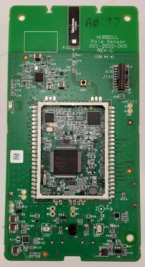
LLB2020001
Apr 04, 2022Aclara Core Module transceiver
Equipment Class
TNB - Licensed Non-Broadcast Station Transmitter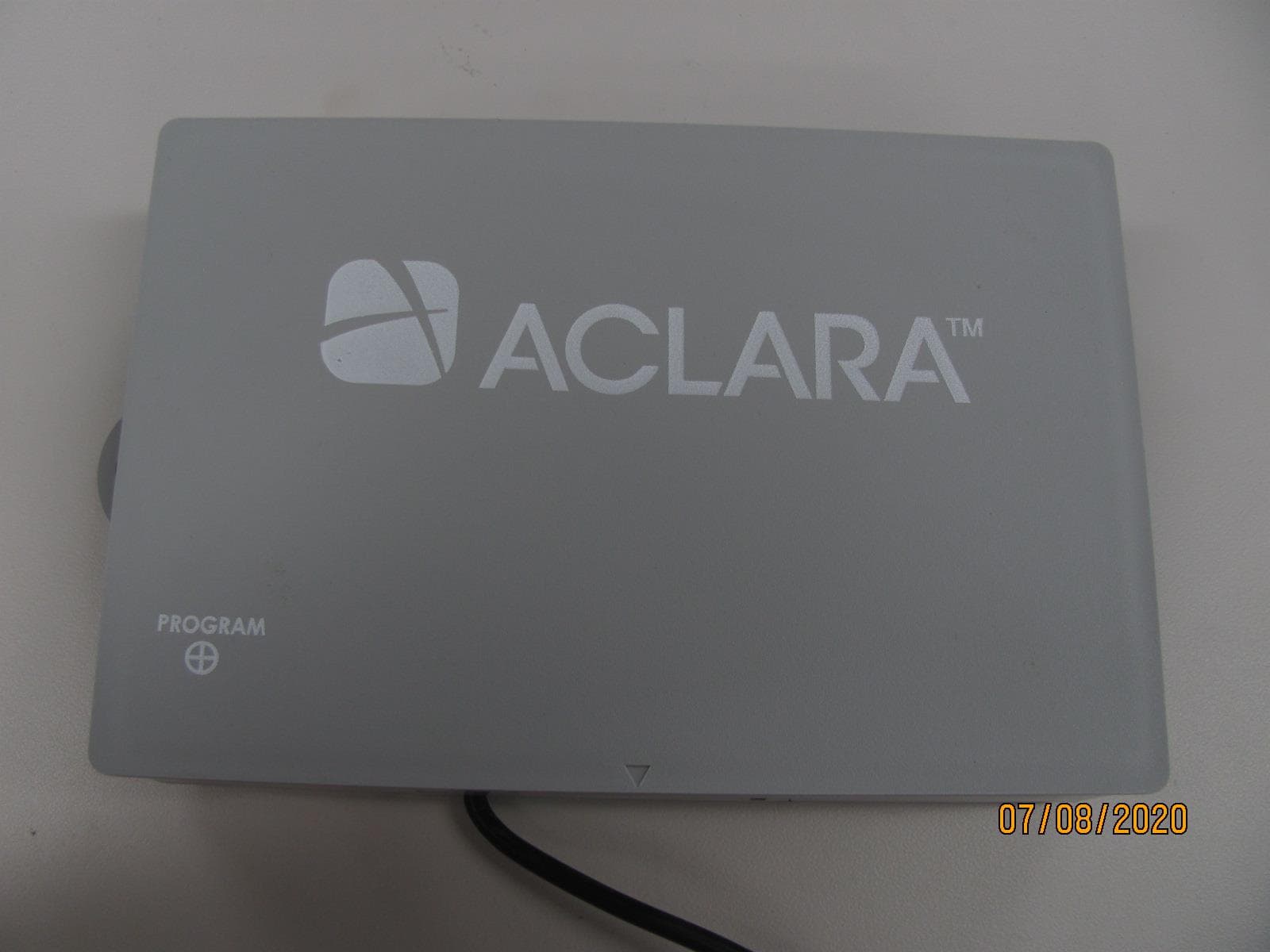
LLB2019006
Aug 04, 2020Water Meter Transponding Unit (MTU)
Equipment Class
TNB - Licensed Non-Broadcast Station Transmitter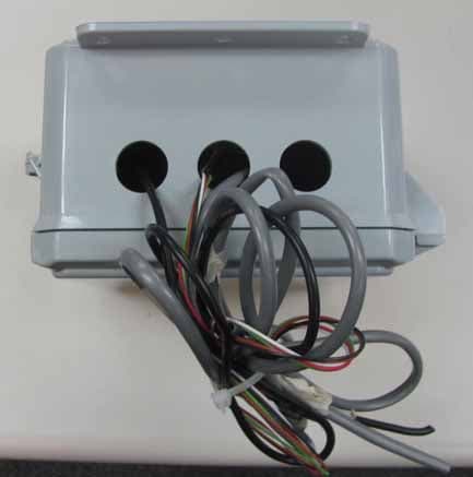
LLB2015001
Dec 10, 2015Series 4000 MTU
Equipment Class
TNB - Licensed Non-Broadcast Station Transmitter