LLB11583-2TRANSMITTER FOR METER READING
Aclara Technologies LLC
Click to zoom
Application Details
- Equipment Class
- TNB - Licensed Non-Broadcast Station Transmitter
- Date of Grant
- Sep 12, 2011
- Application Purpose
- Original Equipment
- Date of Application
- Sep 06, 2011
- Equipment Note
- TRANSMITTER FOR METER READING
- Frequency Range
- 450.00000000 - 470.00000000
- Company
- Aclara Technologies LLC
- Country
- United States
Documents & Files
Document Text
Text extracted from the exhibit documents filed with the FCC. Open a document above to read the original.
Users Manual
MTU Instructions ALL MTU Instructions as of 10/1/2009 October, 2009 Instructions Included Document Page 471-2000 – General Installation & Wiring Guidelines ........................................................ 3 471-2001 – for Rockwell/Equimeter/Sensus Gas Meters (Direct Mount).......................... 15 471-2002 – for Most Popular Water Meters........................................................................ 19 471-2003 – for American Meter Company Gas Meters (Direct Mount)............................. 25 471-2004 – for American Meter Company Gas Meters (Indirect Mount)........................... 29 471-2005 – for Carson Industries Pit Lids.......................................................................... 33 471-2006 – for Armor Access Pit Lids................................................................................ 37 471-2007 – for Invensys/Icon MTU/Electric Meter ............................................................. 41 471-2008 – for Hexagram Submetering Pulse Adapters .................................................. 43 471-2009 – for AMCO/ABB Water Meters........................................................................... 51 471-2010 – for Neptune/Schlumberger Water Meters ....................................................... 55 471-2011 – for Sensus/Invensys Water Meters ................................................................. 59 471-2012 – for Hersey Water Meters................................................................................... 61 471-2013 – for Badger Water Meters .................................................................................. 63 471-2014 – for M-Log Sensors ............................................................................................ 65 471-2015 – for Rockwell/Equimeter Intermediate/Large Capacity Gas Meters .............. 67 471-2016 – for American Commercial/Industrial Gas Meters .......................................... 73 471-2017 – for Sprague/Schlumberger 250 Gas Meters (Bracket-direct-mount).............. 79 471-2018 – for Lancaster 250 Gas Meters (Bracket-direct-mount)..................................... 83 471-2019 – for Lancaster 175 Gas Meters (Bracket-direct-mount)..................................... 87 471-2020 – for Mini-Max ....................................................................................................... 91 471-2021 – for Sprague 175 Gas Meters (Indirect Mount).................................................. 95 471-2022 – for Metron-Farnier Water Meters.................................................................... 101 471-2023 – for Nicor Composite Pit Lids.......................................................................... 103 471-2026 – for American Meter Commercial & Industrial Diaphragm Gas Meters (Hexagram Large Meter Pulser)............................................................................................ 107 471-2027 – for Rockwell/Equimeter Intermediate and Large Capacity Gas Meters (Hexagram Large Meter Pulser)............................................................................................ 109 471-2028 – for Actaris Commercial & Industrial Diaphragm Gas Meters (Hexagram Large Meter Pulser)............................................................................................ 119 471-2029 – for Dresser Roots-type Gas Meters................................................................ 125 471-2030 – for Romet Roots-type Gas Meters.................................................................. 131 Page 1 MTU Instructions ALL MTU Instructions as of 10/1/2009 Instructions Included (Continued) Document Page 471-2031 – for Actaris/Schlumberger/Sprague ‘Slant-face’ Gas Meters........................ 137 471-2032 – for Armorcast Composite Pit Lids.................................................................. 141 471-2033 - for Actaris/Schlumberger/Sprague Pit/Curbside Gas Meters ...................... 145 471-2034 – for American Meter Company 5B-225 Gas Meters........................................ 149 471-2035 - for Sensus/Equimeter/Rockwell 415 Gas Meters........................................... 153 471-2036 - for Sensus/Equimeter/Rockwell 175S Gas Meters ........................................ 157 471-2037 - for Sensus/Equimeter/Rockwell 175-EMCO Gas Meters............................... 161 471-2038 - for Sensus/Equimeter/Rockwell Residential Gas Meters (Indirect Mount)... 163 471-2040 – for Landis & Gyr Focus Family Electric Meters ............................................ 167 471-2041 – for Landis & Gyr S4 Family Electric Meters .................................................. 169 471-2042 – for DFW Rectangular Composite Pit Lids...................................................... 171 471-2043 – for Carson Industries Polyplastic Pit Lids..................................................... 175 471-2044 – for Sensus/Equimeter/Rockwell Gas Meters (Metric - direct mount)............ 179 471-2045 – for Mid-States 12" Round Pit Lids.................................................................. 183 471-2046 – for Alliance Rectangular Pit Lids.................................................................... 187 471-2047 - for Actaris/Schlumberger/Sprague ‘Flat-face’ Gas Meters ........................... 189 471-2051 – for Actaris Dattus fm2 and fm3 Commercial & Industrial Diaphragm Gas Meters .......................................................................................................195 471-2052 – for Severn-Trent SmartMeter Water Meters................................................... 197 471-2053 – for Endress & Hauser PROMAG Water Meters ............................................. 199 471-2054 – for Actaris Cyble Water Meters....................................................................... 201 Page 2 MTU Instructions General Installation and Wiring Guidelines The FCC wants you to know..... This equipment has been tested and complies with Part 15…
Text truncated - open the document above for the full version.
Cover Letter(s)
August 23, 2011 Aclara RF, Inc. 30400 Solon Rd. Solon, OH 44139 440-528-7451 Federal Communications Commission Office of Engineering and Technology Equipment Approval Services RE : Application for obtaining a transmitter approval Attached Application Form 731 FCC ID: LLB11583-2 Dear Sir or Madam: Aclara RF Inc. wishes to obtain an approval for a telemetry transmitter (MTU) with the FCC ID LLB11583-2. The specifics of this transmitter: the LLB11583-2 transmitter is working in conjunction with Sprague family of gas utility meters. Previously, similar transmitter (LLB11583) of Aclara RF is approved by FCC on 2-13-2007. The differences in current application are: The LLB11583-2 is matched to the latest modification of the Sprague Gas meters. The current MTU has efficient RF amplification. The transmitter section has better harmonic and spurious filtering. Much efficient power supply is used to prolong product life and enhance product quality. Consequently, the PCB is redesigned to fit new circuitry. Complete information about LLB11583-2 device is documented in the attached circuit schematics and photographs. The LLB11583-2 transmitter was tested for conformance to the technical requirements of 90.201 Subpart I-General Technical Standards. Results of tests are attached to this application. The LLB11583-2 was found to be in conformance with all technical requirements of 90.201. Sincerely, Lazar Feldman Principal Engineer RF & Microwave Technology Aclara RF 440-528-7451 [email protected]
Cover Letter(s)
Page 1 of 14 Master Agr-rev06.10.10 MASTER AGREEMENT This Master Agreement is made and entered into as of the ___ day of _____, 201_ (the “Effective Date) by and between: Aclara RF Systems Inc. an Ohio corporation 30400 Solon Road Solon, OH 44139 (Referred to herein as “ACLARA”) and (Referred to herein as (“Purchaser”) Collectively, ACLARA and Purchaser may be referred to as “Parties.” Whereas, ACLARA has developed a proprietary Radio Frequency (RF) communication system comprised of equipment and software (the “STAR® Network System”) that provides for communication with electric, gas and water meters and other devices; and Whereas, Purchaser desires to acquire from ACLARA a STAR Network System to be utilized by Purchaser for the automated meter reading of residential, industrial and commercial meters and for other purposes; Now, Therefore, in consideration of the mutual covenants set forth herein, and intending to be legally bound, the Parties agree as follows: 1. Definitions. The following words and phrases shall have the following meanings for the purposes of this Master Agreement. a) “Master Agreement” means this document and the following Exhibits all of which are attached hereto and made a part hereof, and any amendments, modifications or supplements thereto or attachments incorporated therein: i) Exhibit A—List of Deliverables and Pricing ii) Exhibit B—Software License Agreement iii) Exhibit C—Warranties b) “Deliverables” mean the Equipment, Software License and Services listed on Exhibit A—List of Deliverables and Pricing. Page 2 of 14 Master Agr-rev06.10.10 c) “Commercially Reasonable Efforts ” means taking all such steps and performing in such a manner as a well managed company would undertake where it was acting in a determined, prudent and reasonable manner. . d) “Contract Manufacturers” means those entities that manufacture proprietary ACLARA designed equipment. e) “ACLARA Licensed Software” shall have the meaning as it is defined in Exhibit B—Software License Agreement. f) “ACLARA Personnel” means all employees of ACLARA, ACLARA’s subcontractors and their employees, or any other personnel assigned by ACLARA to provide work pursuant to this Master Agreement. ACLARA Personnel shall not include any Purchaser Personnel. g) “Delivery” means, in the case of Equipment purchased hereunder, the loading of the equipment on the means of transport of the carrier selected by ACLARA pursuant to Article 9, below. ”Delivery” means, in the case of Services provided hereunder, the periodic performance of such Services as described herein. h) “Equipment” means that equipment described on Exhibit B—List of Deliverables, Pricing and Delivery Dates that is manufactured by ACLARA or by a Contract Manufacturer. “Equipment” shall not include equipment manufactured by a third party not a Contract Manufacturer, purchased by ACLARA and re-sold pursuant to this Master Agreement. i) “Project Schedule” shall mean the schedule developed in accordance with Article 3, below. j) “Purchaser Personnel” means all employees of Purchaser, Purchaser’s subcontractors and their employees, or any other persons or entities assigned by Purchaser to provide materials, services or labor in furtherance of Purchaser’s installation, deployment and use of Purchaser’s STAR Network System. Purchaser Personnel shall not include any ACLARA Personnel. k) “Services” shall mean those services to be performed by ACLARA as described in herein. l) “Third Party Licensed Software” shall have the meaning as it is defined in Exhibit B—Software License Agreement. Page 3 of 14 Master Agr-rev06.10.10 m) “Work” means all obligations, duties and responsibilities of the Parties necessary to be performed by them in order to accomplish all of their respective obligations under this Master Agreement. 2. Work. Upon the effective date of this Master Agreement, ACLARA shall provide all necessary equipment, software, management, supervision, materials, tools, supplies, facilities and resources necessary to perform its Work in accordance with the terms of this Master Agreement. Upon the effective date of this Master Agreement, Purchaser shall provide all necessary management, supervision, resources and materials required (but not to be supplied by ACLARA hereunder) to perform its Work in accordance with the terms of this Master Agreement. 3. Project Schedule. ACLARA and Purchaser shall meet as expeditiously as possible after the execution of this Agreement to discuss the Start Up Checklist or Project Schedule and related matters (“the kickoff meeting”). Program Managers from ACLARA and Purchaser are responsible for monitoring the Start Up Checklist or Project Schedule so that the delivery dates shown on Exhibit B are met. 4. Term. The term of this Master Agreement shall become effective on the date first above written and shall continue in full force and effect (unless earlier terminated in accordance with this Master Agreement) for a period of ___ months. The Work shall be substantially accomplished within this period unless the Parties agree to an extension of the term of this Master Agreement. Notwithstanding such termination, certain rights and obligations arising under this Master Agreement, including, but not limited to, those contained in Exhibit C—Software License Agreement shall survive the termination of this Master Agreement. The term of this Master Agreement may be extended by mutual agreement of the Parties. The Parties acknowledge that Purchaser may desire to purchase additional equipment following the Expiration of this Agreement. In such case, any such purchases shall be at such prices and delivery shall occur on such dates as the Parties may then agree. All other terms and conditions contained in this Master Agreement shall apply to such Purchases. 5. Time for Performance. a) ACLARA shall use Commercially Reasonable Efforts to deliver the Equipment and Software and provide the Services within the times set forth on Exhibit A. Purchaser …
Text truncated - open the document above for the full version.
External Photos
LLB11583-2 Aclara RF EXTERNAL PICTURES Front View LLB11583-2 Aclara RF Back View LLB11583-2 Aclara RF Side View End of the file.
ID Label/Location Info
LLB11583-2 Aclara RF FCC Label Location FCC Label Location
ID Label/Location Info
.0005 1/2 D C B A A B C D SCALE: SIZE CAD FILE: DWG. NO. B SHEET 1 OF 1 REV. DATE APPROVALS DRAWN CHECKEDRESP ENG MFG ENGQUAL ENG UNLESS OTHERWISE SPECIFIED DIMENSIONS ARE IN INCHES TOLERANCES ARE: FRACTIONS DECIMALS ANGLES MATERIAL FINISH DO NOT SCALE DRAWING APPLICATION USED ON NEXT ASSY 1 2 3 4 5 6 7 8 8 7 6 5 4 3 2 1 REVISIONS REV. LABEL, FCC ID, LLB11583-2 DJG THE WRITTEN PERMISSION OF ACLARA RF SYSTEMS INC . IS PROHIBITED. DATE .010 .XXX= ACLARA RF SYSTEMS INC. ANY REPRODUCTION IN PART OR WHOLE WITHOUT APPROVED THE INFORMATION CONTAINED IN THIS DRAWING IS THE SOLE PROPERTY OF SEE NOTES .XX= .005 .XXXX= 1/64 DJG 08/29/11 091-LLB11583-2 4:1 091-LLB11583-2 N/A A 08/29/11 DESCRIPTION A BY DJG 08/29/11 DJGDJG 08/29/11 ECO ##### - INITIAL RELEASE (C) 2011 ACLARA RF SYSTEMS INC. ALL RIGHTS RESERVED. PROPRIETARY AND CONFIDENTIAL. 4) TEXT COLOR TO BE BLACK3) TEXT TO BE MINIMUM OF 0.125" HIGHNOTES:1) MATERIAL: 4 MIL PRINTABLE POLYESTER/HIGH STRENGTH ACRYLIC SOLVENT ADHESIVE(AVERY) FASSON SPEC #72828 OR EQUIVALENT 2) BACKGROUND COLOR TO BE PANTONE 429 GRAY P R E L I M I N A R Y 0 8 / 2 9 / 1 1 .75 .25
Test Report
1 James R. Pollock HEXAGRAM INC. An ESCO Technologies Company 30400 Solon Road Solon OH 44139 (440) 528-7200 ENGINEERING TEST REPORT Rev 1 RADIO-FREQUENCY EMISSIONS TEST REPORT FOR GAS METER TRANSMITTING UNIT Model 11583-2, Rev. A FCC ID: LLB11583-2 August 2, 2011 Changes made in revision 1 of this report: Corrected Error in calibration date of HP8340; page 8 Page numbers inserted in to report Report Prepared by Agency Certification Control Technician 2 TEST REPORT INTRODUCTION The Hexagram Model 11583-2 transceiver is a “Meter Transmitting Unit” (MTU) designed to provide remote meter reading capability for gas meters. The transceiver is self- powered and mounts directly on a gas meter. On board batteries provide power. The transmitter provides a very short, intermittent radio frequency transmission to send a remote reading of the meter to a data collector unit. A microprocessor provides timing, control and data processing functions. The internal antenna is inaccessible to the user and no external antenna is provided. A prototype unit was used as a test subject for this report. This report presents the data obtained in support of an application certification under Part 90 of the FCC rules. MEASUREMENTS PERFORMED Power Output and Spurious Emissions Page 3 with test set up photographs Occupied Bandwidth Page 9 Frequency Stability vs. Temperature Page 11 Frequency Stability vs. Supply Voltage Page 12 Transient Stability Page 14 3 POWER OUTPUT AND SPURIOUS EMISSIONS Within the tuning range of 450 – 470 MHz, the transmitter portion of the Model 11583-2 (EUT) was examined at three fundamental frequencies and their harmonics. All measurements below 1 GHz were made at a 3-meter distance on the Smith Electronics open area test site located at 8200 Snowville Road, Brecksville, OH. Data pertinent to this site is on file with the FCC (Reg. #90938). The harmonic measurements above 1 GHz were made at a distance of 1 meter over a suitable ground plane. The measurements were made using the substitution method described in TIA/EIA-603-C. Tuned dipoles were used for measurements below 1000 MHz and a wave-guide antenna was used above 1000 MHz. A spectrum analyzer was used as a receiver. The transmitter was placed on a remotely rotatable, non-conducting test stand. This general set up is shown in Pictorial 1. Because of the intermittent nature of the normally operating transmitter, the transmitter was forced to transmit continuously for about 20 seconds at a 50% duty cycle for these measurements. Power to the meter necessary to sustain the transmission was provided by a 12 VDC battery. With the transmitter powered and the test receiver tuned to the unmodulated signal, the transmitter under test was rotated to the position of maximum signal. The receiving antenna was then varied between 1 and 4 meters in height to again maximize the signal. Measurements were made with the antennas positioned both vertically and horizontally and the maximum signals recorded. Peak detection was used for the signals below 1000 MHz and average detection above 1000 MHz. After the maximum received meter readings were obtained for each frequency and polarity, the transmitter under test was removed from the area and replaced by a signal generator and transmitting antenna. With the transmit antenna placed as close as possible to the position of the test unit, the signal generator was activated at a test frequency. With the signal detected, the receiving antenna was positioned for maximum reception. The signal generator output was then adjusted until the received signal was equal to the previously received signal from the unit under test. These measurements were repeated for each frequency and antenna orientation and the maximum values obtained are noted in Tables 1a – 1c. In order to convert the signal generator output value to equivalent radiated power from a dipole, the following equation is used: P d = P g – cable loss(dB) + antenna gain(dB d ) where: P d is the dipole equivalent power in dBm, P g is the generator output into the substitution antenna, also in dBm, and “antenna gain” is the dB gain of the substitution antenna with respect to a theoretical dipole. According to 90.210(d)(3) all emissions greater than 12.5 kHz from the center of the authorized band shall be attenuated below the unmodulated carrier by 50 + 10log(P). The determined power outputs, the required harmonic attenuation as well as the attenuation for each harmonic are found in Tables 1a – 1c. 4 TABLE 1a PICTORIAL 1 HEXAGRAM MODEL 11583-2 MTU OUTPUT POWER AND SPURIOUS EMISSIONS TYPICAL TEST SETUP 5 TABLE 1a HEXAGRAM MODEL 11583-2 TRANSMITTER SUBSTITUTION METHOD 450 MHz Horizontal 3 meter measurement using tuned dipole antenna Freq. (MHz) Gen. Output (dB) Coax Loss (dB) Ant. Gain (dBd) Dipole Eq. Power (dBm) Difference (dB) 450 26.3 2.0 -0.2 24.1 900 -35.2 2.9 -0.5 -38.6 -62.7 Horizontal 1 meter measurement using horn antenna Freq. (MHz) Gen. Output (dBm) Coax Loss (dB) Ant. Gain (dBd) Dipole Eq. Power (Dbm) Difference (dB) 1350 -60.7 0.8 5.5 -56.0 -80.1 1800 -65.3 1.0 5.9 -60.4 -84.5 2250 -63.7 1.2 6.8 -58.1 -82.2 2700 -59.7 1.3 7.6 -53.4 -77.5 3150 -61.0 1.4 7.7 -54.7 -78.8 3600 -53.0 1.6 7.7 -46.9 -71.0 4050 -47.5 1.7 7.6 -41.6 -65.7 4500 -48.9 1.8 8.3 -42.4 -66.5 Vertical 3 meter measurement using tuned dipole antenna Freq. (MHz) Gen. Output (dB) Coax Loss (dB) Ant. Gain (dBd) Dipole Eq. Power (dBm) Difference (dB) 450 28.1 2.0 -0.2 25.9 900 -33.1 2.9 -0.5 -36.5 -62.4 Vertical 1 meter measurement using horn antenna Freq. (MHz) Gen. Output (dBm) Coax Loss (dB) Ant. Gain (dBd) Dipole Eq. Power (Dbm) Difference (dB) 1350 -59.3 0.8 5.5 -54.6 -80.5 1800 -64.0 1.0 5.9 -59.1 -85.0 2250 -62.5 1.2 6.8 -56.9 -82.8 2700 -60.2 1.3 7.6 -53.9 -79.8 3150 -67.5 1.4 7.7 -61.2 -87.1 3600 -53.5 1.6 7.7 -47.4 -73.3 4050 -52.3 1.7 7.6 -46.4 -72.3 4500 -47.0 1.8 8.3 -40.5 -66.4 Output = 24.1dBm = 0.257 W Req. Att.= 44.1 dBm Output = 25.9 dBm = 0.389 W Req. Att.= 45.9 dBm 6 TABLE …
Text truncated - open the document above for the full version.
Contact Information
Applicant
John Cunningham(VP, Chief Engineer)
Test Firm
Smith Electronics, Inc.James Pollock
Technical Specifications
| # | Rule Parts | Frequency Range | Power Output | Emission | Tolerance |
|---|---|---|---|---|---|
| 1 | 90 | 450 MHz - 470 MHz | 389.00 mW | 7K20F1D | 2.5000000000 ppm |
Other Applications from Aclara Technologies LLC
LLB-095370
Jun 18, 2026Wireless Current Sensor for Capacitor Bank Applications
Equipment Class
DTS - Digital Transmission System
LLBY84092-1
Nov 10, 2022RF Endpoint
Equipment Class
TNB - Licensed Non-Broadcast Station Transmitter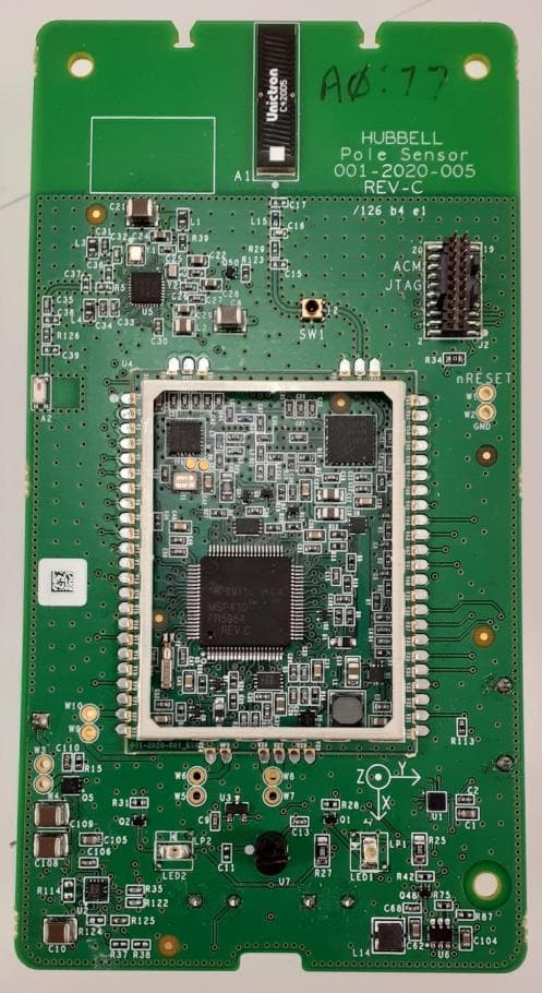
LLB2020001
Apr 04, 2022Aclara Core Module transceiver
Equipment Class
TNB - Licensed Non-Broadcast Station Transmitter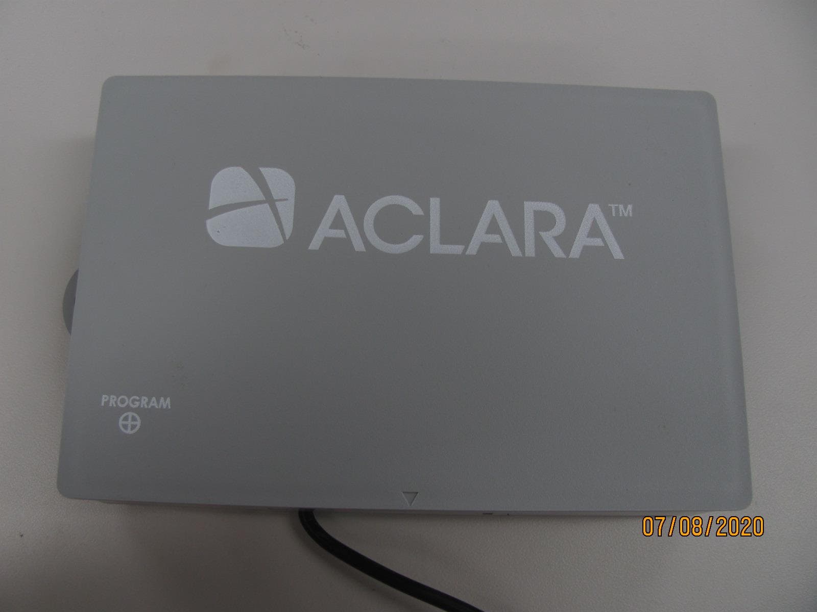
LLB2019006
Aug 04, 2020Water Meter Transponding Unit (MTU)
Equipment Class
TNB - Licensed Non-Broadcast Station Transmitter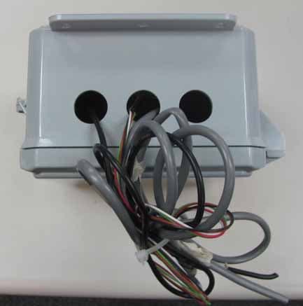
LLB2015001
Dec 10, 2015Series 4000 MTU
Equipment Class
TNB - Licensed Non-Broadcast Station Transmitter