LLB5373AData Collection Unit
Aclara Technologies LLC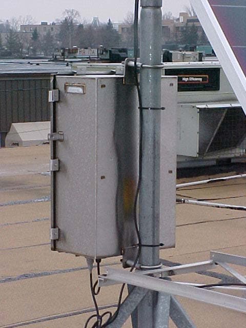
Click to zoom
Application Details
- Equipment Class
- CXX - Communications Rcvr for use w/ licensed Tx and CBs
- Date of Grant
- Mar 15, 2004
- Application Purpose
- Original Equipment
- Date of Application
- Mar 15, 2004
- Equipment Note
- Data Collection Unit
- Frequency Range
- 450.00000000 - 470.00000000
- Company
- Aclara Technologies LLC
- Country
- United States
Documents & Files
Document Text
Text extracted from the exhibit documents filed with the FCC. Open a document above to read the original.
Cover Letter(s)
March 10, 2004 HEXAGRAM, Inc. 23905 Mercantile Rd. Cleveland, OH 44122 216-464-1057 Federal Communications Commission Office of Engineering and Technology Equipment Approval Services RE : Application for obtaining a transmitter approval Attached Application Form 731 FCC ID: LLB5373A Dear Sir or Madam: Hexagram Inc. wishes to obtain an approval for telemetry Data Collection Unit (DCU) with the FCC ID LLB5373A. The DCU consists of a radio receiver and computer circuitry. DCU has function of collecting data from wireless communication with surrounded Hexagram transmitters. Complete information about LLB5373A device is documented in the attached circuit schematics and photographs. The LLB5373A DCU was tested for conformance to the technical requirements of 15.101 Technical Standards. Results of tests are attached to this application. The LLB5373A was found to be in conformance with all technical requirements of 15.101. Sincerely, Lazar Feldman Principal Engineer RF & Microwave Technology Hexagram Inc. 216-464-1057 x1229
Cover Letter(s)
March 16, 2004 HEXAGRAM, Inc. 23905 Mercantile Rd. Cleveland, OH 44122 216-464-1057 Federal Communications Commission Office of Engineering and Technology Equipment Approval Services RE : Request for Confidentiality Attached Form 731 – Application FCC ID: LLB5373A Dear Sir or Madam: Hexagram Inc. does not wish to publicly disclose certain technical information which is enclosed with this application. This material contains critical trade secrets and we request that the Commission withhold this information from public inspection pursuant to the provisions of Section 0.457(d) and 0.459 of the Commissions Rules, and Section 552(b)(4) of the Freedom of Information Act. MATERIAL TO BE HELD CONFIDENTIAL (LLB5373A): File Name Description Pages LLB5373A--Internal Photos.pdf Internal Circuit Board Photos ten pages LLB5373A- –Schematic of RX and DCU.pdf Circuit Schematics Five pages LLB5373A --Operation Desc.pdf Description of Operation One page LLB5373A -Installation.pdf Installation manual Thirty five pages LLB5373A -Block Diagram.pdf Block Diagram of the device One page LLB5373A –DCU Bill of materials.pdf bill of materials of DCU Thirty six pages LLB5373A –Radio Receiver Bill of materials.pdf RX bill of materials Nine pages LLB5373A--Tune Up.pdf Field calibration and tune up One page The LLB5373A electronic assembly is sealed inside of a Plastic Enclosure which cannot be opened without destruction of the seal. The above listed material is confidential and is not available to the public or end user. Sincerely Lazar Feldman Principal Engineer RF & Microwave Technology Hexagram Inc. 216-464-1057 x1229
External Photos
LLB5373A External Photos DCU Installed on a roof DCU in Metal Box Solar Cell Back View on DCU Front View on DCU
ID Label/Location Info
FCC: LLB5373A
Test Report
SMITH ELECTRONICS, INC. ELECTROMAGNETIC COMPATIBILITY LABORATORIES RADIO-FREQUENCY EMISSIONS TEST REPORT FOR HEXAGRAM, INC. DATA COLLECTOR UNIT (DCU) RECEIVER Model 5373A FCC ID: LLB5373A March 10, 2004 Prepared by: Prepared for:Hexagram, Inc. 23905 Mercantile Road Cleveland, OH 44122 Smith Electronics, Inc. 8200 Snowville Road Brecksville, OH 44141 Phone: (440) 526-4386 Fax: (440) 526-9205 James R. Pollock 2 TEST REPORT OBJECTIVE Measurements were performed on December 11 & 12, 2003, to determine if the Hexagram Model 5373A DCU was in compliance with the FCC emissions requirements of 15.109 and 15.111 for a digital device and a receiver. SUMMARY The Hexagram Model 5373A DCU was found to be in compliance with the radiated radio frequency emissions requirement of the FCC for a digital device and a receiver when installed in its weatherproof metal enclosure. The DCU would be considered a Class A digital device but was found to meet the more stringent Class B requirements which are the same requirements as for the receiver. GENERAL INFORMATION MANUFACTURERHexagram, Inc. 23905 Mercantile Road Cleveland, OH 44122 TEST DATESDecember 11 & 12, 2003 EQUIPMENT UNDER TESTHexagram Model 5373A Data Collection Unit (DCU) Receiver TEST SPECIFICATIONFCC Part 15 15.109(a)(b), 15.111(a) 3 MEASUREMENT EQUIPMENT Spectrum AnalyzerHewlett Packard Type 8568B with 85680A RF Spectrum Analyzer section SN: 2216A02120 85662A display section SN: 2152A03683 Calibrated: 6/03 Quasi-Peak AdapterHewlett Packard Model: 85650A SN: 2043A00350 Calibrated: 6/03 Spectrum AnalyzerHewlett-Packard Type 8593EM SN: 3536A00147 Calibrated: 1/04 PreamplifierHewlett Packard Type 8447D SN: 1937A03103 Gain: 26 dB Vector PlotterHewlett Packard Type 7407A SN: 2308A39494 LISN’s50 uH LISN’s per ANSI C63.4-1992 Biconical AntennaEMCO Model: 3104 Frequency Range: 30-200 MHz Log Periodic AntennaEMCO Model: 3146 Frequency Range: 200-1000 MHz Ridged Wave-Guide AntennaEMCO Model 3115 Frequency Range: 1 – 18 GHZ Coaxial CableType RG-214/U 1 m length 2 m length 4 INTRODUCTION The Hexagram Data Collector Unit (DCU) receiver is a battery powered receiving system intended to be centrally located within an area with a distribution of Hexagram Meter Transmitting Units (MTU’s). The MTU’s periodically transmit untility meter data which is received and stored by the DCU. At predetermined intervals, the DCU transmits the data to a central location using a cellular telephone installed within the DCU enclosure. The DCU is installed within a plastic housing, which is, in turn, mounted in a steel, weather-proof, enclosure. The receiving antenna, the cell phone antenna, and a solar panel are mounted externally to the steel enclosure. The DCU also contains the digital hardware necessary for operation and data storage, and is thus a Class A digital device as well as a receiver. The receiver is to tune within the 450 MHz – 470 MHz band and is a super- heterodyne receiver with an IF frequency of 85.86 MHz. The local oscillator (LO) of the system operates 85.86 MHz above the tuned frequency. The receiver input contains a band-pass filter that reduces any extraneous input signal and also contains the LO frequency and its harmonics within the system. This report describes the tests performed on the receiver in support of an application for certification. MEASUREMENTS PERFORMED Antenna Power ConductionPage 5 Radiated Receiver/Digital EmissionPage 5 .The receiver and microprocessor portions of the DCU was examined for radiated emissions per Part 15, and has been determined to comply with the appropriate sections of that part (15.109 & 15.111). The data used for determining compliance is presented in this report. 5 ANTENNA POWER CONDUCTION EMISSIONS Emissions from the antenna port of a receiver are required to be 2 nW or less. Two nanowatts is equivalent to –57 dBm. The antenna port of the DCU was attached to the spectrum analyzer input port with a 1 meter length of RG-214/U. The loss in this length of cable ranges from less than 0.1 dB at 100 MHz to less than 1 dB at 5 GHz. The emissions over the frequency range of 0 to 5 GHz was measured in two analyzer scans, 0 – 2.921 GHZ and 2.679 – 5 GHz. The –57 dB level was shown on each scan. The measured values were not closer than 10 dB below the limit level. A sample of the emissions without the input filter installed is shown in Fig. 1. On these scans, the LO signals are clearly visible and do approach the –57 dB level. For these scans the receiver was tuned to 460.1 MHz, near mid-band. Figures 2 – 4 show the antenna terminal emissions with the appropriate filter installed for each frequency. The tuned frequencies shown are: Fig. 2, 450.0 MHz, Fig. 3, 460.1 MHz, and Fig. 4, 470.0 MHz. With the filter installed, no significant emissions are visible from the antenna port except for a small peak at about 2.7 GHz in Fig. 2. A minimum of 15 dB clearance to the –57 dB limit is maintained. The emissions from the antenna port of the DCU are well below the limit of 2 nW. RADIATED EMISSIONS The radiated emissions from the DCU system were examined in the shielded room. The measurements were made at a distance of 1 meter, with the receiver and cell- phone antennas installed as can be seen in Pictorial 1. The receiver portion of the DCU was investigated from 200 MHz to 5 GHz. The digital portion of the DCU was scanned between 30 MHz and 1000 MHz. Figure 5 shows the scans made between 30 MHz & 1000 MHz with the enclosure closed as for normal operation. The information shown is basically the ambient level inside the shielded room. These plots cover the range required for the digital device and would be well below the Class B limit which is shown on the plots. As no emissions could be detected in the room at one meter, it was determined not necessary to make open field measurements at three meters. Because no receiver emissions were detected with the steel enclosure properly closed, a set of measurements was taken with the enclosure door open.…
Text truncated - open the document above for the full version.
Contact Information
Applicant
John Cunningham(VP, Chief Engineer)
Test Firm
Smith Electronics, Inc.James Pollock
Technical Specifications
| # | Rule Parts | Frequency Range | Power Output |
|---|---|---|---|
| 1 | 15B | 450 MHz - 470 MHz | - |
Other Applications from Aclara Technologies LLC
LLB-095370
Jun 18, 2026Wireless Current Sensor for Capacitor Bank Applications
Equipment Class
DTS - Digital Transmission System
LLBY84092-1
Nov 10, 2022RF Endpoint
Equipment Class
TNB - Licensed Non-Broadcast Station Transmitter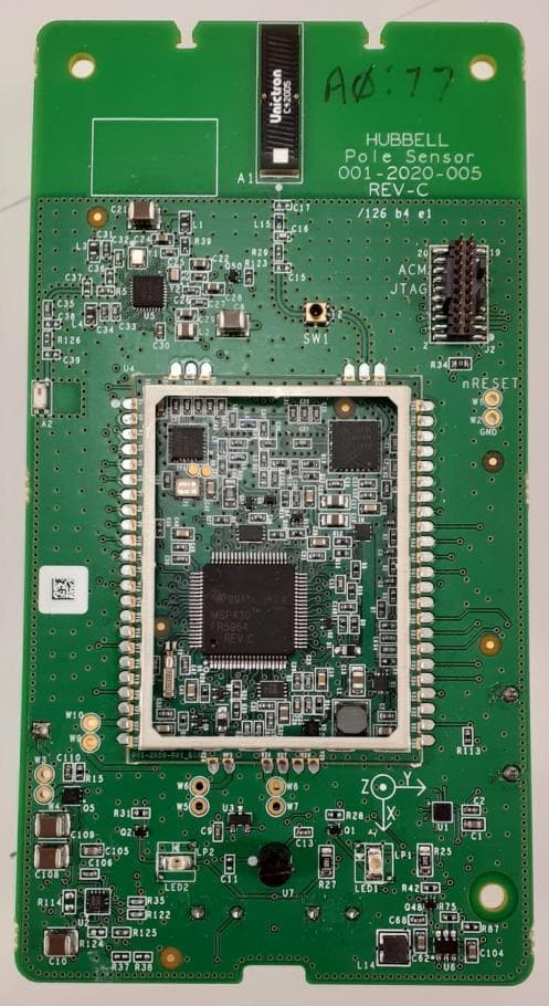
LLB2020001
Apr 04, 2022Aclara Core Module transceiver
Equipment Class
TNB - Licensed Non-Broadcast Station Transmitter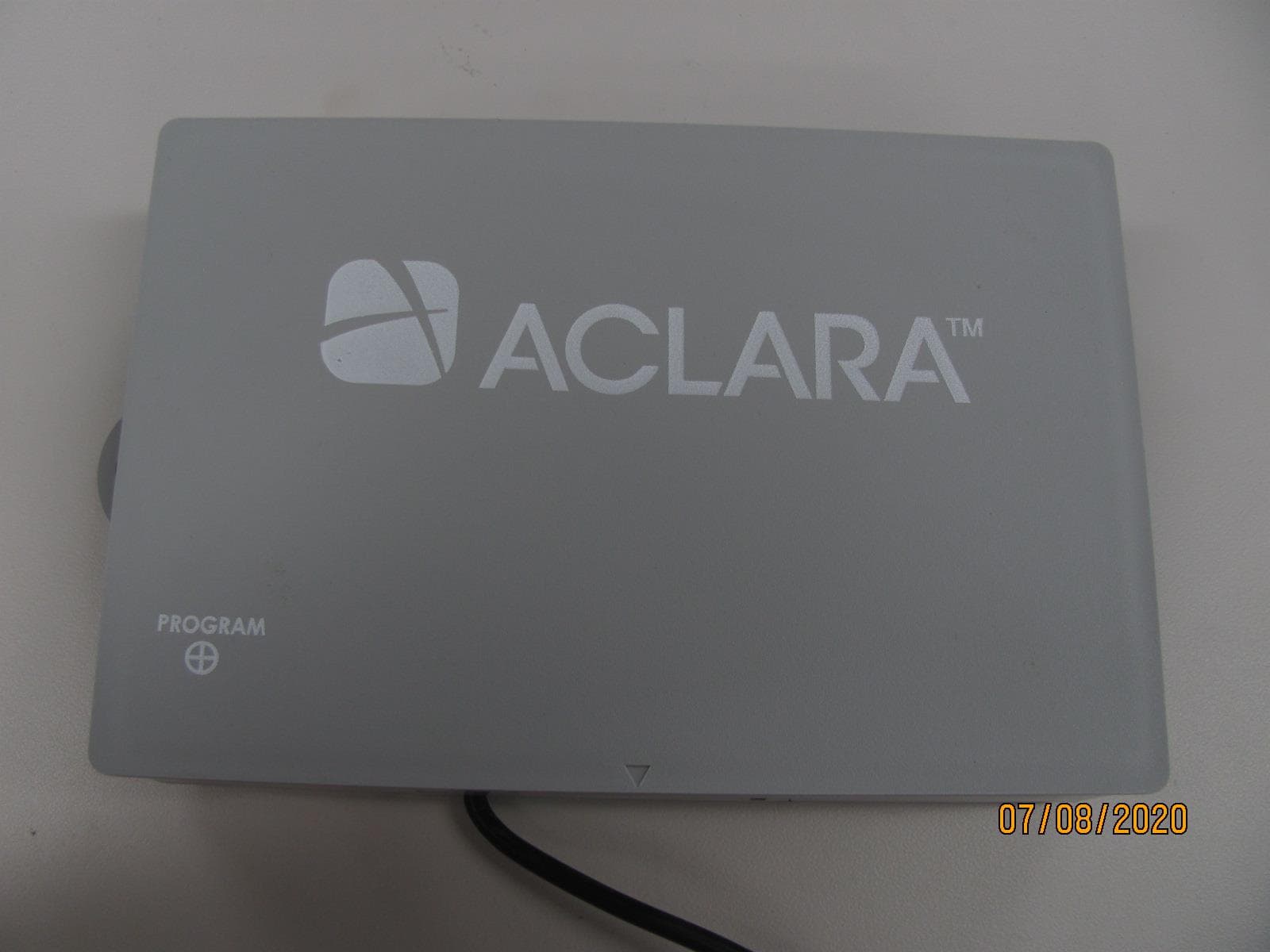
LLB2019006
Aug 04, 2020Water Meter Transponding Unit (MTU)
Equipment Class
TNB - Licensed Non-Broadcast Station Transmitter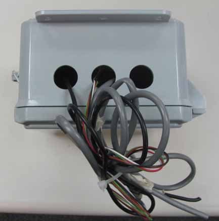
LLB2015001
Dec 10, 2015Series 4000 MTU
Equipment Class
TNB - Licensed Non-Broadcast Station Transmitter