LLB6327Telemetry Transmitter for Automatic Meter Reading
Aclara Technologies LLC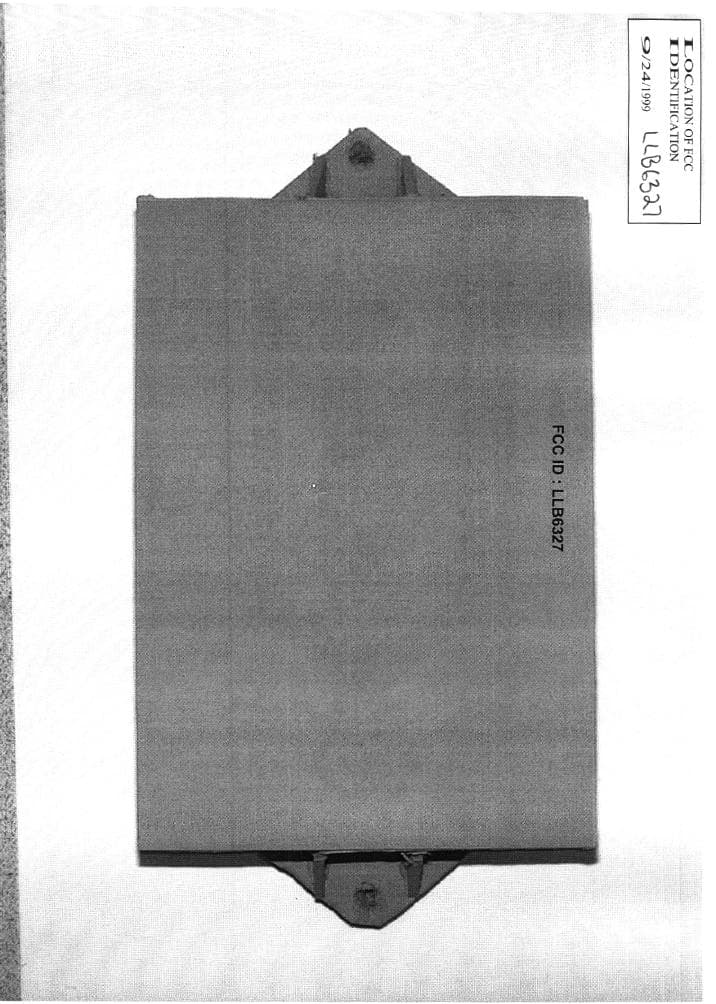
Click to zoom
Application Details
- Equipment Class
- TNB - Licensed Non-Broadcast Station Transmitter
- Date of Grant
- Jan 20, 2000
- Application Purpose
- Original Equipment
- Date of Application
- Sep 29, 1999
- Equipment Note
- Telemetry Transmitter for Automatic Meter Reading
- Frequency Range
- 450.00000000 - 470.00000000
- Company
- Aclara Technologies LLC
- Country
- United States
Documents & Files
Document Text
Text extracted from the exhibit documents filed with the FCC. Open a document above to read the original.
Users Manual
EXHIBIT F DRAFT OF INSTRUCTION SHEET LLB6327 STAR FIXED NETWORK AMR FLAT-PACK MTU P/N 6327 INTRODUCTION The STAR Flat-Pack Meter Transmission Module (MTU) is designed to be wall- mounted near a water, gas, or electric utility meter. A two or three conductor cable extends from the unit and connects to the associated utility meter. The electronic components are permanently sealed inside a rugged plastic housing. There are no adjustments or user-serviceable parts. LOCATING THE MTU The MTU is designed to be mounted on the outside wall of a structure when the utility meter is outdoors. It should be located as high as possible above ground, and at least six inches from metal objects such as wires, pipes, downspouts, etc. When the utility meter is located in the basement, the MTU must be mounted as high as possible to maximize transmission range. Ideally, the MTU should be mounted on a wall or joist high in the basement ceiling. If the basement ceiling is finished, mount the MTU on the wall at the ceiling level. The MTU should be at least four inches from metal objects including wires, heating ducts, pipes, etc. The radio signals are broadcast out of the front and back of the MTU, so it should not be placed where a large metal object, such as a furnace, is located directly in front of the MTU and within five or ten feet. MOUNTING THE MTU The MTU mounts with two screws using the recessed holes in the enclosure. Only the screws provided with the MTU should be used. They are to be tightened to a torque of 15 ounce-inches. If it is necessary to mount the MTU on a masonry wall, plastic anchors are used with the screws. WIRING Route the cable to the utility meter and wire per the instructions provided with the meter register. LLB6327 PROGRAMMING The MTU is programmed using the “Walkabout” programmer (P/N 501-5884A) and programming probe (P/N 501-5884B). Programming may be performed by the meter vendor, the meter shop, or in the field. Even if programming is performed at the factory or meter shop, it is still necessary to use the programmer to initiate MTU operation at the time of field installation. Refer to the “Walkabout” manual for programming information.
Cover Letter(s)
LLB6327 LIST OF EXHIBITS 1. Cover Letter Request for Confidentiality Previous Type Acceptance of Similar Device 2. Exhibit A ID Label Photo 3. Exhibit B Circuit Board Photos 4. Exhibit C Block Diagram, Schematic 5. Exhibit D Description of Operation 6. Exhibit E Test Reports 7. Exhibit F Instruction Manual Sept. 24, 1999 Federal Communications Commission Office of Engineering and Technology Equipment Approval Services RE: Request for Confidentiality Attached Form 731 – Application for Equipment Authorization FCC ID: LLB6327 Dear Sir or Madam: Hexagram, Inc. does not wish to publicly disclose certain technical information which is enclosed with this application. This material contains critical trade secrets and we request that the Commission withhold this information from public inspection pursuant to the provisions of Section 0.457(d) of the Rules. MATERIAL TO BE HELD CONFIDENTIAL: Exhibit BCircuit Board PhotosTwo pages Exhibit CBlock Diagram, Schematics Four pages Exhibit DDescription of OperationTwo pages This material is confidential and is not available to the public or end user. Sincerely, Lawrence M. Sears Director of Technology LS/sd Enclosure LLB6327 PREVIOUS TYPE ACCEPTANCE OF SIMILAR DEVICE The radio transmitter submitted (LLB6327) herein is used as a telemetry device for the reading of utility meters. An operationally identical device (LLB6082) was previously submitted for Type Acceptance and received a Grant of Type Acceptance on March 4, 1998. This earlier version has been in field service since the grant was issued. The product described in this application (LLB6327) is a modified version of LLB6082. The Block Diagram and basic circuit configuration of the new product is identical to that of the original LLB6082. As detailed in Exhibit D: Description of Operation, the semiconductor lineup has been changed from the LLB6082 device in order to improve efficiency, reduce component count, and reduce manufacturing cost. Specific changes are shown below. • RF power amp – higher efficiency, higher output power • Voltage controlled Oscillator – miniaturization, cost • Data filter – miniaturization • RF preamp – higher efficiency, higher output power • 3.3 vdc regulator – miniaturization, cost • Rectifier diodes – miniaturization, cost • Digital Transistors – miniaturization, cost Also attached is a “Statement Concerning Compliance with Section 90.203 (j) (3).” The identical statement was submitted with the application for Type Acceptance of the earlier LLB6082 device. Please Note: An essentially identical transmitter (LLB6717) was submitted for Type Acceptance at the same time as this application. The same Statement Concerning Compliance was enclosed with that application. LLB6327 STATEMENT CONCERNING COMPLIANCE WITH SECTION 90.203(j)(3) Introduction Section 90.203(j)(3) of the Commission’s Rules on transmitters provides, in pertinent part: If the equipment [in the 150-174 and 421-512 MHz bands] is capable of transmitting data and has an overall bandwidth of 6.25 kHz or more, the equipment must be capable of supporting a minimum data rate of 4800 bits per second per 6.25 kHz of bandwidth. 1 Three parties interested in remote utility metering sought reconsideration of this provision to allow alternative showings of spectrum efficiency for low power frequency reuse systems. 2 The Commission replied: [W]e will provide manufacturers with additional flexibility to design spectrally efficient transmitters. The Commission’s Equipment Authorization Division may, on a case by case basis, grant type acceptance to equipment with slower bit rates than specified in Sections 90.203(j)(3) and 90.203(j)(5) of our rules, provided that an acceptable technical analysis is submitted with the application which demonstrates that the slower data rate will provide more spectral efficiency than the standard data rate. 3 The present application is for automatic remote meter reading equipment, and falls squarely within the scope of this exception. When considered as part of a system, the device in question provides spectrum efficiency and channel utilization far in excess of 4800 bits/sec per 6.25 kHz. Technical Analysis The device submitted for type acceptance is a Meter Transmitter Unit (MTU). When the system is implemented, an MTU is attached to each utility meter. The MTU periodically transmits meter readings omnidirectionally in transmissions lasting under one-tenth second each. Transmissions from different MTUs are independent and uncorrelated. ___________________ 1 47 C.F.R. para. 90.203(j)(3). This provision governs Part 90 type acceptance applications filed from August 1, 1996, through December 31, 2004. 2 Replacement of Part 90 by Part 88 to Revise the Private Land Mobile Radio Services, 11 FCC Rcd 17676, 17686 (1996). 3 Id., 11 FCC Rcd at 17687 (emphasis added). LLB6327 Data Collection Units (DCUs) are mounted on a nominal one mile grid. A DCU receives and stores the transmissions from all the MTUs in its range. Once daily, each DCU transfers the accumulated data to a central computer at the utility office via a cellular phone mounted on the DCU. MTU bandwidth is 12.5 kHz, so a strict application of Section 90.203(j)(3) would require the equipment to support a data rate of 9600 bits/sec. In fact, to minimize component cost and bit error rate, an individual MTU transmits at the rate of 1200 bits/sec. The system achieves spectrum efficiency not through a high bit rate in each individual MTU, but through a high level of frequency re-use achieved by deploying a large number of low-power short range transmitters. As detailed in the attached Appendix, a typical large installation of MTUs on a single 12.5 kHz channel can support data rates exceeding 100,000 bits/sec. This performance represents spectrum efficiency far in excess of that required under Section 90.203(j)(3). Where a typical commercial user of private land mobile radio spectrum, such as a delivery service, requires a pair of channels to provi…
Text truncated - open the document above for the full version.
Cover Letter(s)
LLB6327 LIST OF EXHIBITS 1. Cover Letter Request for Confidentiality Previous Type Acceptance of Similar Device 2. Exhibit A ID Label Photo 3. Exhibit B Circuit Board Photos 4. Exhibit C Block Diagram, Schematic 5. Exhibit D Description of Operation 6. Exhibit E Test Reports 7. Exhibit F Instruction Manual Jan. 19, 2000 Federal Communications Commission Office of Engineering and Technology Equipment Approval Services RE: Request for Confidentiality Attached Form 731 – Application for Equipment Authorization FCC ID: LLB6327 Application Confirmation Number: EA95536 Correspondence Reference Number: 11513 731 Dear Sir or Madam: This letter is a replacement for the original cover letter dated Sept. 24/99 that was filed with the LLB6327 application referenced above. The only change is that the item titled “Exhibit B Circuit Board Photos Two pages” has been removed from the list of “Material to be Held Confidential”. All other text in this cover letter remains the same as in the original. Hexagram, Inc. does not wish to publicly disclose certain technical information which is enclosed with this application. This material contains critical trade secrets and we request that the Commission withhold this information from public inspection pursuant to the provisions of Section 0.457(d) of the Rules. MATERIAL TO BE HELD CONFIDENTIAL: Exhibit CBlock Diagram, Schematics Four pages Exhibit DDescription of OperationTwo pages This material is confidential and is not available to the public or end user. Sincerely, Lawrence M. Sears Director of Technology LS/sd Enclosure LLB6327 PREVIOUS TYPE ACCEPTANCE OF SIMILAR DEVICE The radio transmitter submitted (LLB6327) herein is used as a telemetry device for the reading of utility meters. An operationally identical device (LLB6082) was previously submitted for Type Acceptance and received a Grant of Type Acceptance on March 4, 1998. This earlier version has been in field service since the grant was issued. The product described in this application (LLB6327) is a modified version of LLB6082. The Block Diagram and basic circuit configuration of the new product is identical to that of the original LLB6082. As detailed in Exhibit D: Description of Operation, the semiconductor lineup has been changed from the LLB6082 device in order to improve efficiency, reduce component count, and reduce manufacturing cost. Specific changes are shown below. • RF power amp – higher efficiency, higher output power • Voltage controlled Oscillator – miniaturization, cost • Data filter – miniaturization • RF preamp – higher efficiency, higher output power • 3.3 vdc regulator – miniaturization, cost • Rectifier diodes – miniaturization, cost • Digital Transistors – miniaturization, cost Also attached is a “Statement Concerning Compliance with Section 90.203 (j) (3).” The identical statement was submitted with the application for Type Acceptance of the earlier LLB6082 device. Please Note: An essentially identical transmitter (LLB6717) was submitted for Type Acceptance at the same time as this application. The same Statement Concerning Compliance was enclosed with that application. LLB6327 STATEMENT CONCERNING COMPLIANCE WITH SECTION 90.203(j)(3) Introduction Section 90.203(j)(3) of the Commission’s Rules on transmitters provides, in pertinent part: If the equipment [in the 150-174 and 421-512 MHz bands] is capable of transmitting data and has an overall bandwidth of 6.25 kHz or more, the equipment must be capable of supporting a minimum data rate of 4800 bits per second per 6.25 kHz of bandwidth. 1 Three parties interested in remote utility metering sought reconsideration of this provision to allow alternative showings of spectrum efficiency for low power frequency reuse systems. 2 The Commission replied: [W]e will provide manufacturers with additional flexibility to design spectrally efficient transmitters. The Commission’s Equipment Authorization Division may, on a case by case basis, grant type acceptance to equipment with slower bit rates than specified in Sections 90.203(j)(3) and 90.203(j)(5) of our rules, provided that an acceptable technical analysis is submitted with the application which demonstrates that the slower data rate will provide more spectral efficiency than the standard data rate. 3 The present application is for automatic remote meter reading equipment, and falls squarely within the scope of this exception. When considered as part of a system, the device in question provides spectrum efficiency and channel utilization far in excess of 4800 bits/sec per 6.25 kHz. Technical Analysis The device submitted for type acceptance is a Meter Transmitter Unit (MTU). When the system is implemented, an MTU is attached to each utility meter. The MTU periodically transmits meter readings omnidirectionally in transmissions lasting under one-tenth second each. Transmissions from different MTUs are independent and uncorrelated. ___________________ 1 47 C.F.R. para. 90.203(j)(3). This provision governs Part 90 type acceptance applications filed from August 1, 1996, through December 31, 2004. 2 Replacement of Part 90 by Part 88 to Revise the Private Land Mobile Radio Services, 11 FCC Rcd 17676, 17686 (1996). 3 Id., 11 FCC Rcd at 17687 (emphasis added). LLB6327 Data Collection Units (DCUs) are mounted on a nominal one mile grid. A DCU receives and stores the transmissions from all the MTUs in its range. Once daily, each DCU transfers the accumulated data to a central computer at the utility office via a cellular phone mounted on the DCU. MTU bandwidth is 12.5 kHz, so a strict application of Section 90.203(j)(3) would require the equipment to support a data rate of 9600 bits/sec. In fact, to minimize component cost and bit error rate, an individual MTU transmits at the rate of 1200 bits/sec. The system achieves spectrum efficiency not through a high bit rate in each individual MTU, but through a high level of frequency re-use achieved by deploying a large number of low-power short range tr…
Text truncated - open the document above for the full version.
Test Report
EXHIBIT E2 Hexagram Transmitter FCC ID: LLB6327 FREQUENCY STABILITY VS. VOLTAGE Instruments Used: HP 500 MHz Universal Counter Model 5328A S/N 1848A10091 10 MHz Rubidium Frequency Standard EFRATOM Model FRK-L S/N 25016879 Fluke Digital Voltmeter Model 8050A Variable DC Power Supply Assigned Frequency = 460.0000 MHz Battery FrequencyVariance Voltage (MHz) (PPM) 3.60459.999 991-0.02 3.50459.999 977-0.05 3.40459.999 998-0.00 3.30460.000 011+0.02 3.20460.000 036+0.08 3.10460.000 042+0.09 3.00460.000 062+0.13 2.90460.000 088+0.19 2.80459.999 925-0.16 2.70459.999 894-0.23 Microcontroller disables operation below this voltage. Measurements made and recorded by: ______________________________ Sept. 27, 1999Nathan R. Jacob P. Eng Hexagram Transmitter FCCC ID: LLB6327 FREQUENCY STABILITY VS. TEMPERATURE Instruments Used: HP 500 MHz Universal Counter Model 5328A S/N 1848A10091 10 MHz Rubidium Frequency Standard EFRATOM Model FRK-L S/N 25016879 Associated Environmental Chamber Model EK2114 Assigned Frequency = 460.0000 MHz TemperatureFrequencyVariance (°C) (MHz) (PPM) 50459.999 602-0.87 40459.999 708-0.64 30459.999 740-0.57 20459.999 622-0.82 10459.999 932-0.15 0459.999 600-0.87 -10459.999 640-0.78 -20459.999 760-0.52 -30460.000 193+0.42 Microcontroller disables operation beyond this temperature range. Measurements made and recorded by: ________________________________ Sept. 27, 1999Nathan R. Jacob P. Eng.
Contact Information
Applicant
John Cunningham(VP, Chief Engineer)
Technical Contact
HexagramLawrence M Sears
[email protected]216-464-1057
23905 Mercantile Rd. · Cleveland, Ohio · United States
Non-Technical Contact
HexagramLawrence M Sears
[email protected]216-464-1057
Test Firm
Smith Electronics, Inc.James Pollock
Technical Specifications
| # | Rule Parts | Frequency Range | Power Output | Emission | Tolerance |
|---|---|---|---|---|---|
| 1 | 90 | 450 MHz - 470 MHz | 620.00 mW | 7K20F1D | 2.5000000000 ppm |
Other Applications from Aclara Technologies LLC
LLB-095370
Jun 18, 2026Wireless Current Sensor for Capacitor Bank Applications
Equipment Class
DTS - Digital Transmission System
LLBY84092-1
Nov 10, 2022RF Endpoint
Equipment Class
TNB - Licensed Non-Broadcast Station Transmitter
LLB2020001
Apr 04, 2022Aclara Core Module transceiver
Equipment Class
TNB - Licensed Non-Broadcast Station Transmitter
LLB2019006
Aug 04, 2020Water Meter Transponding Unit (MTU)
Equipment Class
TNB - Licensed Non-Broadcast Station Transmitter
LLB2015001
Dec 10, 2015Series 4000 MTU
Equipment Class
TNB - Licensed Non-Broadcast Station Transmitter