LLB6717DTransmitter for Meter Reading
Aclara Technologies LLC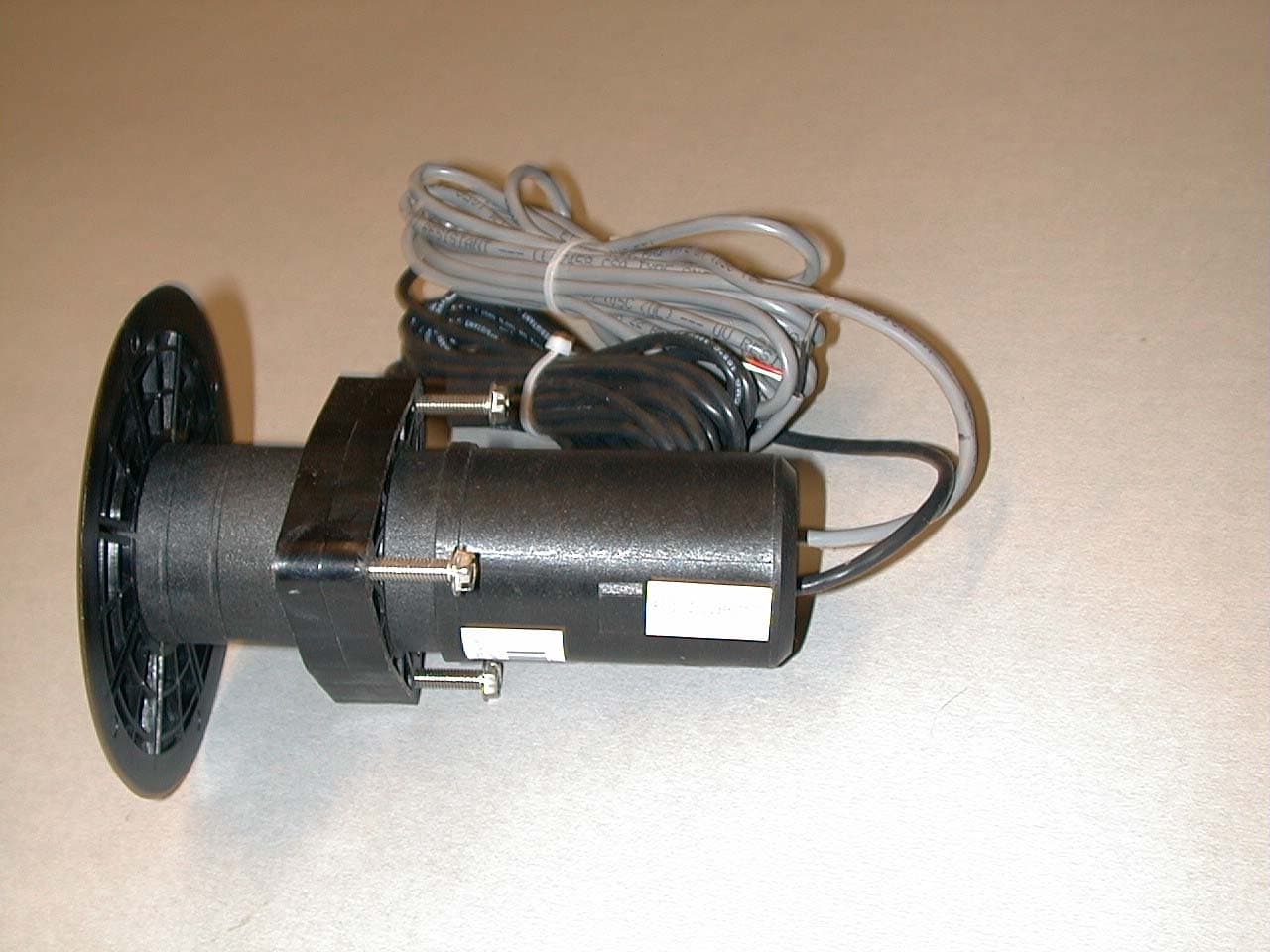
Click to zoom
Application Details
- Equipment Class
- TNB - Licensed Non-Broadcast Station Transmitter
- Date of Grant
- Jan 20, 2003
- Application Purpose
- Original Equipment
- Date of Application
- Jan 20, 2003
- Equipment Note
- Transmitter for Meter Reading
- Frequency Range
- 450.00000000 - 470.00000000
- Company
- Aclara Technologies LLC
- Country
- United States
Documents & Files
Document Text
Text extracted from the exhibit documents filed with the FCC. Open a document above to read the original.
Cover Letter(s)
January 17, 2003 HEXAGRAM, Inc. 23905 Mercantile Rd. Cleveland, OH 44122 216-464-1057 Federal Communications Commission Office of Engineering and Technology Equipment Approval Services RE : Request for Confidentiality Attached Form 731 – Application FCC ID: LLB6717D Dear Sir or Madam: Hexagram Inc. does not wish to publicly disclose certain technical information which is enclosed with this application. This material contains critical trade secrets and we request that the Commission withhold this information from public inspection pursuant to the provisions of Section 0.457(d) and 0.459 of the Commissions Rules, and Section 552(b)(4) of the Freedom of Information Act. This letter summarizes previously sent to request for confidentiality. MATERIAL TO BE HELD CONFIDENTIAL: File Name Description Pages LLB6717D-Int photos.pdf Internal Circuit Board Photos Two pages LLB6717D-Schematic.pdf Circuit Schematics Four Pages LLB6717D-Operation Desc.pdf Description of Operation Two Pages LLB6717D-Installation.pdf Installation manual Thirty seven pages LLB6717D Block Diagram.pdf Block Diagram of the device One page LLB6717D Tune Up.pdf Field Calibration and Tune Up Procedure One page The LLB6717D electronic assembly is permanently sealed inside of a plastic enclosure which cannot be opened without destruction of the packaging. The above listed material is confidential and is not available to the public or end user. Sincerely, Lawrence M. Sears Director of Technology
External Photos
Location of FCC Identification 11.7.02 LLB6717D FCC ID LLB6717D
ID Label/Location Info
Location of FCC Identification 11.7.02 LLB6717D FCC ID LLB6717D
Test Report
Hexagram Transmitter FCC ID: LLB 6717D FREQUENCY STABILITY vs. AMBIENT TEMPERATURE VARIATION With fully functioning PIT SET transmitter unit, the temperature stability of the frequency generating components was observed. The PIT SET was placed in a temperature chamber. The computer which signaled the transmitter to transmit was outside the chamber. A ½ wavelength receiving antenna was inside the chamber with its output going to the frequency measuring spectrum analyzer. With the transmitter programmed to transmit at 460.00000 MHz, the chamber temperature was set to 20° C. After reaching the set temperature, the transmitter was allowed to stabilize for about 10 minutes or more. The transmitter was instructed to transmit, the signal was captured by the spectrum analyzer and the frequency was determined and compared to the expected 460.00000. The temperature in the chamber was then increased in 10° C increments. At each new temperature, time was allowed for stabilization of the transmitter, a transmission was made and the frequency determined. The temperature was increased at the 10° C increments to 70° C, and then reduced back to 20° C where another reading was taken. The temperature was then reduced in 10° C increments, checking the frequency at each point, until a temperature of -30° C was reached. The frequency at each temperature was recorded and is found in Table. It can be seen from the table that all readings are with the 2.5 ppm allowed. Expected Frequency 460.000 MHz Temperature [C] Frequency [MHz[ Variance [PPM] 70 459.999601 -0.867 60 459.999606 -0.857 50 459.999628 -0.809 40 459.999691 -0.672 30 459.999733 -0.580 20 459.999676 -0.704 10 459.999792 -0.452 0 459.999672 -0.713 -10 459.99968 -0.696 -20 459.999812 -0.409 -30 460.00003 0.065 Imbedded microcontroller disables MTU operation outside of this temperature range. Measured and Recorded on December 19, 2002 SUMMARY The Hexagram LLB6717DTransmitting Unit (PIT SET) has been shown to be capable of complying with those requirements of the Federal Communications Commission for a Part 90 transmitter that are covered by this report. EQUIPMENT UNDER TEST “PIT SET Transmitter, LLB6117D MANUFACTURER Hexagram, Inc. 23905 Mercantile Cleveland, OH 44122 TEST DATE December 19, 2002 MEASUREMENT EQUIPMENT Hewlett-Packard Spectrum Analyzer Type 8560A with 8560A RF Section 85650A Quasi-Peak Adapter ANTENNAS ½ WL Dipole Antenna MISCELLANEOUS 7.5 m RG-213/U coaxial cable Environmental Chamber, Model VersaTenn II Temp Range: -73C to +200C Radio Shack 63-1011 Digital Thermometer Lazar Feldman David Allen
Test Report
Hexagram Transmitter FCC ID: LLB6717D FREQUENCY STABILITY vs. VOLTAGE Instruments Used: HP 500 MHz universal Counter Model 5328A 10 MHz Rubidium Frequency Standard EFRATOM Model FRK-L Fluke digital voltmeter Model 8050A Variable DC Power Supply BK Presision-1660 Assigned frequency 460.000 MHz Battery voltage Frequency [MHz[ Variance [PPM] 3.60 459.999 992 -0.02 3.50 459.999.995 -0.02 3.40 49.999 999 0.00 3.30 460.000 010 +0.02 3.20 460.000 033 +0.07 3.10 460.000 040 +0.09 3.00 460.000 061 +0.13 2.90 460.000 085 +0.18 2.80 459.999 946 -0.17 2.70 459.999 898 -0.22 Imbedded microcontroller disables MTU operation below 2.70 Volts. Measured and Recorded on November 4, 2002 Lazar Feldman David Allen
Test Report
SMITH ELECTRONICS, INC. ELECTROMAGNETIC COMPATIBILITY LABORATORIES RADIO-FREQUENCY SPURIOUSE EMISSIONS TEST REPORT FOR HEXAGRAM, INC. “PIT-SET” TRANSMITTER Model 6717B FCC ID: LLB6717D SIGNAL SUBSTITUTION METHOD January 10, 2003 Prepared by: Prepared for: Hexagram, Inc. 23905 Mercantile Road Cleveland, OH 44122 Smith Electronics, Inc. 8200 Snowville Road Brecksville, OH 44141 Phone: (440) 526-4386 Fax: (440) 526-9205 James R. Pollock TEST REPORT INTRODUCTION The Hexagram “PIT-SET” transmitter is a battery operated transmitter designed to be electrically attached to an in ground utility meter. The transmitter would be mounted in the meter pit and provide a short, intermittent radio frequency transmission to provide a remote reading of the meter. A microprocessor provides timing, control and data processing functions. The built in antenna is inaccessible to the user and no provision is made for an external antenna. This report describes the tests performed on the transmitter for output power and spurious emissions MEASUREMENTS PERFORMED Measurements were made to determine the equivalent output power and the level of harmonic emissions in relation to the fundamental frequency using the substitution test method of TIA-603. POWER OUTPUT AND SPURIOUS EMISSIONS A series of measurements of the operating frequency and any harmonic emissions was made on the Smith Electronics, open field test site located at 8200 Snowville Road, Brecksville, OH. Data pertinent to this site is on file with the FCC. Measurements below 1000 MHz were made at a three-meter test distance with frequencies above 1000 MHz being measured at one meter. A receiver and a tuned dipole were used for receiving below 1000 MHz and a spectrum analyzer and a wave guide antenna above 1000 MHz. The transmitter was suspended from a Ford meter box cover (approx. 10.5” x 7”) This steel cover was placed atop an open cardboard box so that the transmitter body was below the cover. The box and transmitter were placed on a remotely rotatable, non- conducting test stand. This general set up is shown in Pictorial 1. Because of the intermittent nature of the normally operating transmitter, an external battery pack was used and the transmitter was forced to continually transmit for the measurements. With the test receiver tuned to the unmodulated signal, the transmitter was rotated to the position of maximum signal. The receiving antenna was then varied between 1 and 4 meters in height to again maximize the signal. Measurements were made with the antennas positioned both vertically and horizontally and the maximum signal recorded. No differences were observed with different signal detectors, so a quasi-peak detector was used for the signals below 1000 MHz and average detection above 1000 MHz. After the maximum received meter readings were obtained for each frequency and polarity, the meter under test was removed from the area and replaced by a signal generator and transmitting antenna. With the transmit antenna placed as close as possible to the position of the test unit, the signal generator was activated at a test frequency. With the signal detected, the transmit antenna was rotated slightly to maximize the reading. The receive antenna was also positioned for maximum reception. The signal generator output was then adjusted until the received signal was equal to the received signal from the unit under test. These measurements were repeated for each frequency and antenna orientation and the maximum values obtained are noted in Table 1. Antenna gain and coax loss figures are also included in Table 1 In order to convert the signal generator output value to equivalent radiated power from a dipole, the following equation is used: P d = P g – cable loss(dB) + antenna gain(dB d ) where: P d is the dipole equivalent power, P g is the generator output into the substitution antenna and “antenna gain” is the gain of the substitution antenna with respect to a dipole. According to 90.210(d)(3) all emissions greater than 12.5 kHz from the center of the authorized band shall be attenuated below the unmodulated carrier by 50 + 10log(P). Using P = 0.050 W, the required attenuation is 37.0 dB. An examination of Table 1 shows that all emissions are 45.7 dB or more below the carrier level. TABLE 1 HEXAGRAM PIT SET TRANSMITTER SUBSTITUTION METHOD per TIA-603 3 meter measurement using LPA antenna Frequency (MHz) Gen. Output (dB) Coax Loss (dB) Ant. Gain (dBd) Dipole Eq. Power (dBm) Difference (dB) 460 +14.5 0.3 2.8 17.0 -- 920 -33.0 0.5 3.8 -29.7 -46.7 1 meter measurement using horn antenna Frequency (MHz) Gen. Output (dBm) Coax Loss (dB) Ant. Gain (dBd) Dipole Eq. Power (dBm) Difference (dB) 1380 -41.0 0.7 3.1 -38.6 -55.6 1840 -41.0 0.8 4.9 -36.9 -53.9 2300 -37.6 0.9 5.6 -32.9 -49.9 2760 -34.6 1.1 6.2 -29.5 -46.5 3220 -34.2 1.2 6.7 -28.7 -45.7 3680 -35.3 1.3 6.6 -30.0 -47.0 4140 -33.8 1.4 6.5 -28.7 -45.7 4600 -42.2 1.5 7.2 -36.5 -53.5 17 dBm = 50.1 mW or 0.050 W Required attenuation for harmonics is 50 + log (.05) = 37.0 dB Transmitter Meter Box Cover PICTORIAL 1 HEXAGRAM PIT-SET TEST SET UP PICTORIAL 2 HEXAGRAM SUBSTITUTION METHOD TEST SET UP Above 1000 MHz Below 1000 MHz TEST INFORMATION SUMMARY The Hexagram “Pit-Set” transmitter, modified by changing the power amplifier and removing an RF shield, has been shown to be capable of complying with those requirements of the Federal Communications Commission for a Part 90 transmitter regarding output power and spurious emissions. EQUIPMENT UNDER TEST “Pit-Set” Transmitter, FCC ID: LLB6717D MANUFACTURER Hexagram, Inc. 23905 Mercantile Cleveland, OH 44122 TEST DATE October 1 & 25, 2002 & January 8, 2003 TEST EQUIPMENT USED RECEIVERS Singer-Stoddart EMI Field Intensity Meter Model NM 37/57 S/N 0366-06168 Calibrated 6/02 Hewlett-Packard Spectrum Analyzer Model 8593EM S/N 3536A00147 Calibrated 6/00 SIGNAL GENERATORS Marconi Model 2955 S/N 1319281034 < 1 GHz Calibrated 10/02 Agilent Model 83711B S/N US37101420 1 – 20 GHz Calibr…
Text truncated - open the document above for the full version.
Test Report
Transient Frequency Behavior LLB6717 November 5/02 Page 1 of 10 November 5, 2002 FCC ID : LLB6717D TRANSIENT FREQUENCY BEHAVIOR Test Setup The modified LLB6717D transmitter was tested for transient frequency behavior using the test method TIA/EIA-603. The test setup is shown in Fig. 1. The 5373-LZ test receiver with audio bandwidth set to16kHz (low pass) was used. The receiver is furnished with 14.4 MHz high-stability reference generator. The storage oscilloscope was triggered in a presence of an RF radiation from the transmitter which was delayed using a variable digital delay build into the oscilloscope. The 1 kHz test signal was provided by the Marconi Signal Generator. The 1 kHz signal was attenuated by a build into Marconi attenuator to insure 50 dB down from the received signal of LLB6717D. Figure 1 Test Setup Transient Frequency Behavior LLB6717 November 5/02 Page 2 of 10 Test Requirements The test requirements per 90.214 are: 1. Frequency deviation during t 1 (10ms duration after t on ) may be greater than +/-12.5 kHz because output power is less than 6 watts. 2. Frequency deviation during t 2 (25 ms duration after t 1 ) must be less than +/-6.25 kHz. 3. Frequency deviation after t 2 must be less than +/-2.5ppm x 460MHz = +/-1.15 kHz. 4. Frequency deviation during t 3 (10ms duration after transmitter is turned off) may exceed +/-12.5 kHz because output power is less than 6watts. Test Data Figures 2 through 8 show the measured LLB6717D Transient Frequency characteristics. The limit masks are shown overlaid on figures 3 through 6. Time scale used on Fig.2 is 1 ms., Figures 3 through 5 and Fig.8 is 5ms per division, Fig.6 is 10 ms per division, Fig. 7 is 2.5 ms/div. Deviation scales of 4 kHz per division and 0.8 kHz per division were used in order to better resolve details of the waveforms. Measured waveforms include the following. Figure 2: 1kHz Test Signal +/-12.5kHz Deviation – 4kHz per Division Figure 3: LLB6717D Turn On – Test Signal Modulated – 4kHz per Division Figure 4: LLB6717D Turn On – Test Signal Unmodulated – 4kHz per Division Figure 5: LLB6717D Turn On – Test Signal Modulated – 0.8kHz per division Figure 6: LLB6717D Turn On – Test Signal Unmodulated – 0.8kHz per Division Figure 7: LLB6717D Turn Off – Test Signal Modulated – 4kHz per division Figure 8: LLB6717D Turn Off – Test Signal Modulated – 0.8kHz per division Transient Frequency Behavior LLB6717 November 5/02 Page 3 of 10 Transient Frequency Behavior LLB6717 November 5/02 Page 4 of 10 Transient Frequency Behavior LLB6717 November 5/02 Page 5 of 10 Transient Frequency Behavior LLB6717 November 5/02 Page 6 of 10 Transient Frequency Behavior LLB6717 November 5/02 Page 7 of 10 Transient Frequency Behavior LLB6717 November 5/02 Page 8 of 10 Transient Frequency Behavior LLB6717 November 5/02 Page 9 of 10 Transient Frequency Behavior LLB6717 November 5/02 Page 10 of 10 Test Results Figure 2 shows the receiver response to the 1kHz test signal. Figure 4 shows the turn on response with the test signal unmodulated in order to identify the T on point. Figure 3 shows the LLB6717D turn on response is well within the required +/-6.25kHz during interval T 2 . Interval T 2 starts 10ms after T on and continues for duration of 25ms. There is no transient frequency limit specified during interval t1 since the output power does not exceed 6watt. Figure 6 show that the LLB6717D frequency accuracy is well within the requirement of +/-1.15 kHz from the end of T 2. Figure 7 and 8 show the LLB6717D turn off response. There is no transient frequency limit during interval T3 since the output power does not exceed 6watt. Conclusion The modified model of the Hexagram LLB6717D transmitter has been shown to be capable of complying with the requirements of the FCC Part 90 transmitter that is covered by this report. Measurements made and recorded on November 4, 2002 by: Lazar Feldman David Allen, Measurement Equipment Hewlett Packard Spectrum Analyzer model 8560A Option 003 high stability reference Marconi Instruments Radio Communications Test Set model 2955A Tektronix Digital Storage Oscilloscope model TDS350 Hexagram Test receiver 5373-LZ with high stability reference oscillator.
Contact Information
Applicant
John Cunningham(VP, Chief Engineer)
Test Firm
Smith Electronics, Inc.James Pollock
Technical Specifications
| # | Rule Parts | Frequency Range | Power Output | Emission | Tolerance |
|---|---|---|---|---|---|
| 1 | 90 | 450 MHz - 470 MHz | 50.00 mW | 7K2F1D | 2.5000000000 ppm |
Other Applications from Aclara Technologies LLC
LLB-095370
Jun 18, 2026Wireless Current Sensor for Capacitor Bank Applications
Equipment Class
DTS - Digital Transmission System
LLBY84092-1
Nov 10, 2022RF Endpoint
Equipment Class
TNB - Licensed Non-Broadcast Station Transmitter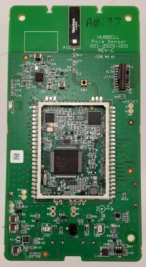
LLB2020001
Apr 04, 2022Aclara Core Module transceiver
Equipment Class
TNB - Licensed Non-Broadcast Station Transmitter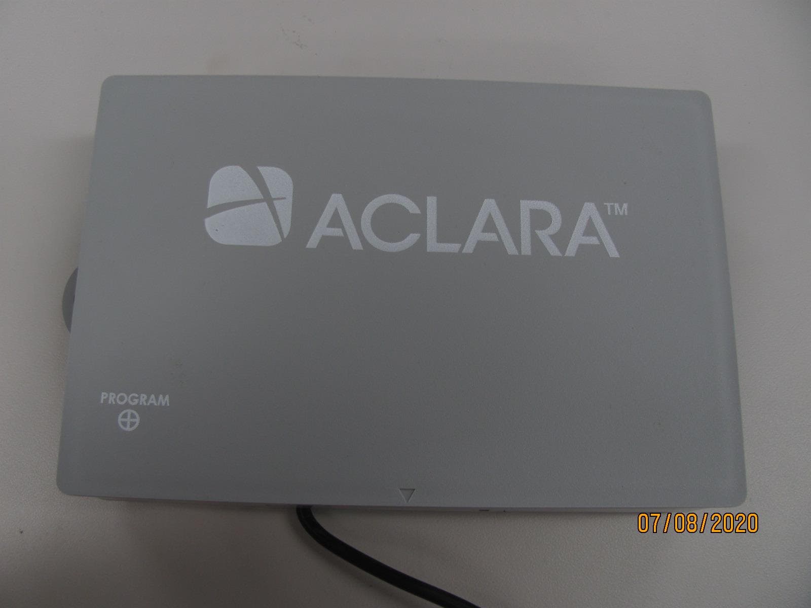
LLB2019006
Aug 04, 2020Water Meter Transponding Unit (MTU)
Equipment Class
TNB - Licensed Non-Broadcast Station Transmitter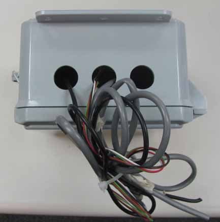
LLB2015001
Dec 10, 2015Series 4000 MTU
Equipment Class
TNB - Licensed Non-Broadcast Station Transmitter