LLIHTM170BLCD Monitor
Hi Tron Systems Inc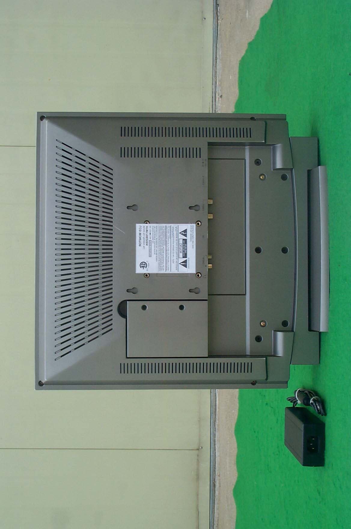
Click to zoom
Application Details
- Equipment Class
- JBP - Part 15 Class B Computing Device Peripheral
- Date of Grant
- May 27, 2003
- Application Purpose
- Original Equipment
- Date of Application
- May 27, 2003
- Equipment Note
- LCD Monitor
- Company
- Hi Tron Systems Inc
- Country
- South Korea
Documents & Files
Document Text
Text extracted from the exhibit documents filed with the FCC. Open a document above to read the original.
Users Manual
INSTRUCTION MANUAL Please read this manual thoroughly before use, and keep it handy for future reference. 17.0" COLOR TFT-LCD MONITOR WARNING: CAUTION: Explanation of Graphical Symbols CAUTIONCAUTION RISK OF ELECTRIC SHOCK DO NOT OPEN CAUTION: TO REDUCE THE RISK OF ELECTRIC SHOCK, DO NOT REMOVE COVER(OR BACK). NO USER-SERVICEABLE PARTS INSIDE. REFER SERVICING TO QUALIFIED SERVICE PERSONNEL. TO REDUCE THE RISK OF FIRE OR ELECTRIC SHOCK, DO NOT EXPOSE THIS PRODUCT TO RAIN OR MOISTURE. DO NOT INSERT ANY METALLIC OBJECT THROUGH VENTILATION GRILLS. The lightning flash with arrowhead symbol, within an equilateral triangle, is intended to alert the user to the presence of uninsulated "dangerous voltage" within the product's enclosure that may be of sufficient magnitude to constitute a risk of electric shock to persons. The exclamation point within an equilateral triangle is intended to alert the user to the presence of important operating and maintenance (servicing) instructions in the literature accompanying the product. - 2 - - 3 - INFORMATION TO THE USER: THIS EQUIPMENT HAS BEEN TESTED AND FOUND TO COMPLY WITH THE LIMITS FOR A CLASS B DIGITAL DEVICE, PURSUANT TO PART 15 OF THE FCC RULES. THESE LIMITS ARE DESIGNED TO PROVIDE REASONABLE PROTECTION AGAINST HARMFUL INTERFERENCE IN A RESIDENTIAL INSTALLATION. THIS EQUIPMENT GENERATES, USES AND CAN RADIATE RADIO FREQUENCY ENERGY AND, IF NOT INSTALLED AND USED IN ACCORDANCE WITH THE INSTRUCTIONS, MAY CAUSE HARMFUL INTERFERENCE TO RADIO COMMUNICATIONS. HOWEVER, THERE IS NO GUARANTEE THAT INTERFERENCE WILL NOT OCCUR IN A PARTICULAR INSTALLATION. IF THIS EQUIPMENT DOES CAUSE HARMFUL INTERFERENCE TO RADIO OR TELEVISION RECEPTION, WHICH CAN BE DETERMINED BY TURNING THE EQUIPMENT OFF AND ON, THE USER IS ENCOURAGED TO TRY TO CORRECT THE INTERFERENCE BY ONE OR MORE OF THE FOLLOWING MEASURES: - REORIENT OR RELOCATE THE RECEIVING ANTENNA - INCREASE THE SEPARATION BETWEEN THE EQUIPMENT AND RECEIVER - CONNECT THE EQUIPMENT INTO AN OUTLET ON A CIRCUIT DIFFERENT FROM THAT TO WHICH THE RECEIVER IS CONNECTED - CONSULT THE DEALER OR AN EXPERIENCED RADIO/TV TECHNICIAN FOR HELP FCC COMPLIANCE STATEMENT CAUTION: CHANGES OR MODIFICATIONS NOT EXPRESSLY APPROVED BY THE MANUFACTURED COULD VOID THE USER'S AUTHORITY TO OPERATE THE EQUIPMENT. THIS CLASS B DIGITAL APPARATUS COMPLIES WITH CANADIAN ICES-003. NORME NMB-003 DU CANADA. - 4 - 1. 2. 3. 4. 5. 6. 6A. 7. 8. 9. 10. 11. 12. 13. 14. 15. 16. 17. 18. 19. IMPORTANT SAFEGUARDS READ INSTRUCTIONS -- All the safety and operating instructions should be read before the appliance is operated. RETAIN INSTRUCTIONS -- The safety and operating instructions should be retained for future reference. CLEANING -- Unplug video monitor or equipment from the wall outlet before cleaning. Do not use liquid cleaners or aerosol cleaners. Use a damp cloth for cleaning. ATTACHMENTS -- Do not use attachments not recommended by the video monitor or equipment manufacturer as they may result in the risk of fire, electric shock or injury to persons. WATER AND MOISTURE -- Do not use video monitor or equipment near water -- for example, near a bathtub, washbowl, kitchen sink, laundry tub, in a wet basement, or near a swimming pool, or the like. ACCESSORIES -- Do not place video monitor or equipment on an unstable cart, stand or table. The video monitor or equipment may fall, causing serious injury to a child or adult, and serious damage to the equipment. Wall or shelf mounting should follow the manufacturer's instructions, and should use a mounting kit approved by the manufacturer. Video monitor or equipment and cart combinations should be moved with care. Quick stops, excessive force, and uneven surfaces may cause the equipment and cart combination to overturn. VENTILATION -- Slots and openings in the cabinet and the back or bottom are provided for ventilation, and to ensure reliable operation of the video monitor or equipment and to protect it from overheating. These openings must not be blocked or covered. The openings should never be blocked by placing the video monitor or equipment on a bed, sofa, rug, or other similar surface. Video monitor or equipment should never be placed near or over a radiator or heat register. Video monitor or equipment receiver should not be placed in a built-in installation such as a bookcase unless proper ventilation is provided. POWER SOURCES -- Video monitor or equipment should be operated only from the type of power source indicated on the marking label. If you are not sure of the type of power supplied to your home, consult your video monitor or equipment dealer or local power company. For video monitor or equipment designed to operate from battery power refer to the operating instructions. GROUNDING OR POLARIZATION -- This video monitor may be equipped with a polarized alternating - current line plug (a plug having one blade wider than the other). This plug will fit into the power outlet only one way. This is a safety feature. If you are unable to insert the plug fully into the outlet, try reversing the plug. If the plug should still fail to fit, contact your electrician to replace your obsolete outlet. Do not defeat the safety purpose of the polarized plug. Alternate Warnings - This video monitor is equipped with a three-wire grounding-type plug, a plug having a third (grounding) pin. This plug will only fit into a grounding-type power outlet. This is a safety feature. If you are unable to insert the plug into the outlet, contact your electrician to replace your obsolete outlet. Do not defeat the safety purpose of the grounding-type plug. POWER CORDS -- Do not allow anything to rest on the power cord. Do not locate video monitor or equipment where the cord will be abused by persons walking on it. HEED WARNINGS -- Follow all instructions marked on the video monitor or equipment. LIGHTNING -- For added protection for video monitor or equipment during a lightning storm, or when it is left unattended and unused for long p…
Text truncated - open the document above for the full version.
Block Diagram
5 5 4 4 3 3 2 2 1 1 DD CC BB AA K4S1616220-TC80 U701 U303 ANALOG VIDEO J303 Y/C 74LCX14 LM4752TS AUDIO AMP U102 VIDEO BUFFER U301 J101 DC 12V HIGH VOLTAGE HT17E11-400 NJM2503M U601,U602 DC/DC CONVERTER LVDS AUDIO VOLUME U101 24C08 U401 J801 AUDIO IN SI4435DY SCALER TFT PANEL A/D CONVERTER ANALOG RGB MIC4576-3.3BU J201 ANALOG RGB H/V SYNC VIDEO DECODER AT-017SS U501 H/V SYNC VOLUME U901,U902 SYNC DRIVER U203 U402 DC/DC CONVERTER FRAME BUFFER USER BUTTON U803 MTV212MS64 U802 INVERTER MX88L284 J301,J302 COMPOSITE U103 U105 VIDEO EEPROM SI4435DY SN75LVDS83 POWER MICROCONTROLLER U201 SG9884A-110 SI4435DY VPC3230D AUDIO PC NJM2172V MIC4576-5.0BU HTM170B25H BLOCK DIAGRAMA HTM170B25H BLOCK DIAGRAM 11Wednesday, May 07, 2003 Title SizeDocument NumberRev Date:Sheet of DOWN LEF T RIGH T SPEAKER EX IT POWER SPEAKER SOURCE UP MENU 5.0V LCD DC 12V 12.0V SYS 3.3V SYS 5.0V SYS 5.0V LCD
External Photos
SK TECH CO., LTD. Page 1 of 2 SKT SKTFCE-030521-062 FCC ID : LLIHTM170B External Photographs of EUT SK TECH CO., LTD. Page 2 of 2 SKT SKTFCE-030521-062 FCC ID : LLIHTM170B
ID Label/Location Info
SK TECH CO., LTD. Page 1 of 1 SKT SKTFCE-030521-062 FCC ID : LLIHTM170B FCC ID Label Sample
ID Label/Location Info
SK TECH CO., LTD. Page 1 of 1 SKT SKTFCE-030521-062 FCC ID : LLIHTM170B FCC ID Sample Label & Location Information LABELLING REQUIREMENTS PER ∫∫∫∫ 2.928 The Label shown shall be permanently affixed at a conspicuous location on the device and be readily visible to the user at the time of purchase. FCC ID : LLIHTM170B This device complies with part 15 of the FCC Rules. Operation is subject to the following two conditions: (1) This device may not cause harmful interference, and (2) this device must accept any interference received, including interference that may cause undesired operation.
Internal Photos
SK TECH CO., LTD. Page 1 of 10 SKT SKTFCE-030521-062 FCC ID : LLIHTM170B Internal Photographs of EUT SK TECH CO., LTD. Page 2 of 10 SKT SKTFCE-030521-062 FCC ID : LLIHTM170B SK TECH CO., LTD. Page 3 of 10 SKT SKTFCE-030521-062 FCC ID : LLIHTM170B SK TECH CO., LTD. Page 4 of 10 SKT SKTFCE-030521-062 FCC ID : LLIHTM170B SK TECH CO., LTD. Page 5 of 10 SKT SKTFCE-030521-062 FCC ID : LLIHTM170B SK TECH CO., LTD. Page 6 of 10 SKT SKTFCE-030521-062 FCC ID : LLIHTM170B SK TECH CO., LTD. Page 7 of 10 SKT SKTFCE-030521-062 FCC ID : LLIHTM170B SK TECH CO., LTD. Page 8 of 10 SKT SKTFCE-030521-062 FCC ID : LLIHTM170B SK TECH CO., LTD. Page 9 of 10 SKT SKTFCE-030521-062 FCC ID : LLIHTM170B SK TECH CO., LTD. Page 10 of 10 SKT SKTFCE-030521-062 FCC ID : LLIHTM170B
Operational Description
SK TECH CO., LTD. Page 1 of 1 SKT SKTFCE-030521-062 FCC ID : LLIHTM170B Operational Description I. Installing the Video Driver (Windows 95/98) To install the video driver, refer to the following sequence. Select Start/Setting/Control Panel. Click Add New Hardware. Click Next. Click Next after selecting No, the device isn’t in the list. Click Next after selecting No, I want to select the hardware from a list. Click Next after selecting Monitors. Click Have Disk... Insert the supplied 3.5 floppy disk to A Drive. Select OK. Select Next after selecting the same model which you purchased. Click Finish. II. Connections To make a normal connection to the monitor, bring a cord from a camera or other video source to one of the BNC jacks or from a PC to the PC jack on the back of the monitor, Either the left or right BNC jack can be used for input. To other jack may be optionally connected to another user of the same signal. Auto Termination The input circuit of the monitor normally terminates the incoming cable in 75ohms, but these BNCs jack are auto-terminating. When two cables are connected, the internal termination is switched out, letting the final destination equipment provide the end termination. This arrangement is also specially offered for the Y/C(S-Video) jacks.
Schematics
5 5 4 4 3 3 2 2 1 1 DD CC BB AA VOLUM E/RIGHT VOLUME/L EFT SOUR CE POWER UP DOW N EXI T MEN U SVHS VIDEO PC PWR_GREEN PWR_ORANGE ADC0 ADC1 Vcc GND LCD BUTTON.DSNA HTM170B25H_Ass'y Control PWB A 11Wednesday, May 07, 2003 Title SizeDocument NumberRev Date:Sheet of 5V_SYS 5V_SYSR110 2.4KJ D10 6 VA10 0005A150 D10 7 VA10 0005A150 C10 3 10 4_50VZ D10 4 LG204 0 R10 6 1.2KJ R109 1.2KJ SW107 RT- 1105 R115 8.2KJ SW101 RT- 1105 Ass'y Harness Ring GND A CODE NO. : 05501312 R1178.2KJ SW102 RT-1105 CN101 35023-0010 1 2 3 4 5 6 7 8 9 10 11 D10 2 LG20 40 SW108 RT- 1105 SW103 RT- 1105 R114 2.4KJ D10 5 BL-BV T201 SW104 RT- 1105 R111 8.2KJ SW105 RT- 1105 D10 3 LG204 0 R10 2 1.2K J HTM170BHN CONTROL PCB REV.A CODE NO. : 10601059 R113 1.2KJ C10 2 10 4_50VZ R10 3 1.2KJ R10 4 1.2KJ R1168.2KJ R10 5 1.2KJ SW106 RT-1105 R108 3.3KJ R112 3.3KJ
Schematics
5 5 4 4 3 3 2 2 1 1 DD CC BB AA IN1C LowIN1A CTL1A Low CTL1B OUT1 AD_POWER X IN1B XGA & SXGA : R602 HighLow MX_POWER VGA & SVGA : R603 5. CT . 2. C C1608 50V . 1. R R1608 J . 3. 104 25V . 4. CE 85 . High High Hitron Systems Inc. <Doc>A HTM170B25H 11Wednesday, May 07, 2003 Title SizeDocument NumberRev Date:Sheet of PDA4 PDA6 PDA19 PDA22 MDB30 MDB1 PDA1 MDB1 1 MDB26 PDA11 MA0 MDB10 PDA9 MDB23 MDB7 MA6 PDA18 MX_RST PDA4 PDA12 MDB6 PDA11 MDB5MDB17 MA2 PDA8 PDA3 DQMA2 MDB4 MA7 PDA20 I2CDATA MDB18 MA10 MA3 PDA0 MA9 MDB3 PDA20 VDDP7 MA5 PDA23 VDDP2 PDA3 MDB1 DQM1 VDDP3 MDB19 VDDD I2CCLK PDA14 PDA16 PDA13 VDA_VPC VDDP1 MDB11 PDA10 MA8 PDA22 PDA2 AGND1 MDB23MDB1 6 MA5 MDB8 PDA23 3.3V_SYS MDB2 9 DQM2DQM2 MDB14 PDA0 MDB29 MA1 MDB18 PDA15 MDB10 PDA7 VSYNC CTL1A MDB15 AGND 1 VDD_ RB MDB1 3 MDB14 PDA7 PDA11 PDA5 VDDP1 MA10 MDB0 PDA7 PDA0 MDB2 7 I2CCLK DQMA[0..2] MA4 PDA18 PDA17 MA6 DQMA0 VPC_RST MDB9 MA0 PDA1 MA0 PDA9 MA1 MDB22 MA8 MDB27 MDB7 PDA15 MA1 PDA21 PDA1 PDA8 PDA12 MDB20 PDA21 MDB3 MDB28 VPC_OE MA3 VDD_RA PDA2 MDB2MDB31 DQM1 MDB5MA3 MA4 DQM0 VDDD MDB24 PDA14 VPC_RST MDB6 MA6 MDB17 MDB21 PDA13 DQMA1 GB[0..7] PDA5MDB16 DQMA2 MDB8 DQMA1 MA9 PDA10 MDB2 1 MDB25 PDA17 PDA22 MDB12 MA4 HSYNC PDA9 PDA19 PDA6 MA7 PDA8 MDB22 VDDP3 MDB30 PDA5 MA2 MDB12MDB15 PDA19 VDDP2 VDDP7 MA8 MA1 0 I2CDATA PDA4 MDB28 MDB31 DQMA0 PDA10 PDA21 PDA6 VREF PDA12 PDA23 AVDD1 MDB1 9 MA7 MDB[0..31] MDB13 PDA3 LDTG MDB4MDB26MDB20 MA5 PDA14 MDB0 PDA2 A/D_EN_M X VDD_LCD PDA20 MDB2 MA9 PDA[0..23] MA2 MDB2 4 LCD _ON AVDD1 MDB25 MDB9 MA[0..10] CTL1B AD-VDD VDD_VP C LCD_ON LVDS_ ON VRT AD-VD AD-PVD AD-PVD AD-VDAD-PVD BB5 EVENTx9 EVENTx3 BB6 EVENTx6 BB2 GB2 EVENTx7 BB2 BB3 EVENTx2 GB6 EVENTx0 BB0 BB1 GB6 GB2 GB4 GB0 GB4 BB0 BB1 ODDTx3 BB7 GB0 BB4 GB3 GB3 BB6 EVENTx8 BB3 ODDTx7 ODDTx0 GB1 GB7 GB5 GB7 BB7 GB1 BB4 BB[0..7] BB5 GB5 PLLVccB LDTG ODDTx1 LVDSVccA ODDTx6 GB[0..7] LHSYNC PLLVccA ODDTx2 LVSYNC ODDTx4 LVDSVccA EVENTx4 EVENTx1 ODDTx5 EVENTx5 LCKB LVDSVccB LCKA ODDTx9 ODDTx8 BB[0..7] EVENTx[0..9] LCKA Cable_DET PDA16 PDA13 PDA15 GA[0..7] RA[0..7] RA[0..7] GA[0..7] I2CDATA 3.3V_AD 5V 12V12V_SYS1 LVDS_ ON LVDS_ON SDA_DDC SCK_DDC ODDTx[0..9] Mute VOL_CTRL VSYNC VRT VREF HSYNC A/D_EN_MX AD-VDD BA2 BA1 GA0 RA0GA1 RA4 BA6 GA7 GA6 BA3 GA5 RA7 RA4 RA5 BA0 RA3 BA0 RA2 RA5 BA3 GA3 RA3 BA[0..7] BA6 RA1 GA2 BA1 GA6 GA1 GA5 RA7 GA3 BA5 GA0 RA1 BA[0..7] BA4 BA2 BA7 BA4 GA4 RA2 RA0 RA6 BA7 GA2 BA5 GA7 GA4 RA6 LCKB PLLVccB PLLVccA LVDSVccB ODDTx2 EVENTx1 EVENTx2 EVENTx9 EVENTx0 ODDTx1 EVENTx6 ODDTx4 ODDTx9 EVENTx7 EVENTx4 EVENTx3 EVENTx8 ODDTx5 ODDTx6 ODDTx3 ODDTx0 ODDTx8 EVENTx5 ODDTx7 VDD_LCD 5V_SYS 3.3V_SYS RB2 RB7 RB5 RB1 RB0 RB6 RB2 RB[0..7] RB3 RB[0..7] RB4 RB4 RB3 RB0 RB6 RB1 RB7 RB5 VPC_O E BOX Hin LHSYNC LVSYNCCable_DET SW[0..6] SW5 HSYNC_IN SW6 SW8 SW3 SW4 SW8 SB[0..2] 5V_A SW7 VOL_CTRL SB2 SB1 I2CCLK VSYNC_IN SW1 SB0 SW7 PWR SW2 PWR SW6 SW5 SW0 SCK_DDC SDA_DDC SW0 SW2 MX_RST HSYNC_IN SW4 VSYNC_IN CTL1A Z86_RST PDA21 SB1 SW1 SW3 Mute CTL1B SB0 SB2 3.3V_SYS 3.3V_SYS 3.3V_SYS2 3.3V_SYS2 3.3V_SYS 5V_SYS VCC_DV 3.3V_AD 12V_SYS 5V_A 5V_SYS VCC_DV 5V_A 5V_SYS 12V_SYS1 VCC_DA 5V_A 5V_SYS VCC_DA VCC_DA 3.3V_SYS2 3.3V_SYS 3.3V_AD 3.3V_SYS 3.3V_SYS 3.3V_SYS 3.3V_SYS2 3.3V_SYS 3.3V_SYS2 3.3V_SYS 5V_A 12V_SYS 5V_SYS 3.3V_SYS AAAAA A AAAAA A A AA A A AAA AA A AA A 5V_SYS 5V_SYS 5V_SYS 5V_SYS 5V_SYS 5V_SYS 5V_SYS 5V_SYS 5V_A 5V_A 5V_A + CE802 470_16V + CT202 47uF_6.3V C301 104Z R40 7 47 2 B905 HB-1M2012-301 C905 104Z R811100 R344 101 RA303 CN1J4ATD220J C402 330J C501 104Z B903 HB-1M2012-301 + CT901 10uF_10V R816100 C214 104Z C510 104Z + CT904 10uF_10V R41 7 47 2 C205 104Z C210 393K C237 101J + CT810 10uF_10V U201 SG9884A-110 569121720212426353942474951525363738393103113119121122123 481011161819232512412854647484941041141203334434850 102 101 100 99 98 97 96 95 112 111 110 109 108 107 106 105 92 91 90 89 88 87 86 85 82 81 80 79 78 77 76 75 72 71 70 69 68 67 66 65 62 61 60 59 58 57 56 55 115 116 117 29 30 31 32 7 15 22 28 27 40 41 44 45 127 126 125 14 13 118 GND1GND2GND3GND4GND6GND7GND8GND9GND10GND11GND12GND13GND14GND15GND16GND17GND18GND19GND20GND21GND22GND23GND24GND25GND26GND27GND28 VD1VD2VD3VD4VD5VD6VD7VD8VD9 VD10VD11 VDD1VDD2VDD3VDD4VDD5VDD6VDD7VDD8 PVD1PVD2PVD3PVD4PVD5 DrB0 DrB1 DrB2 DrB3 DrB4 DrB5 DrB6 DrB7 DrA0 DrA1 DrA2 DrA3 DrA4 DrA5 DrA6 DrA7 DgA0 DgA1 DgA2 DgA3 DgA4 DgA5 DgA6 DgA7 DgB0 DgB1 DgB2 DgB3 DgB4 DgB5 DgB6 DgB7 DbA0 DbA1 DbA2 DbA3 DbA4 DbA5 DbA6 DbA7 DbB0 DbB1 DbB2 DbB3 DbB4 DbB5 DbB6 DbB7 DATACK /DATACK HSOUT SDA SCL A0 A1 R_IN G_IN B_IN CLAMP CLKINV HSYNC COAST CLKEXT FILT REF_IN REF_OUT /PWRDN SOGIN GND5 SOGOUT C235 104Z + CT31010uF_10V + CT505 10uF_10V C339 222K RA203 CN1J4ATD101J B503 HB-1M2012-301 + CT502 10uF_10V + CE803 100uF_16V R106 0R0 C215 104Z B309 HB-1M2012-301 C321 224_16VZ R217 220 C517 104Z + CT306 47uF_6.3V C106 104Z RA511CN1J4ATD220J RA501CN1J4ATD220J + CT301 10uF_10V U203 74LCX14 1 2 3 4 5 6 78 9 10 11 12 13 14 B202 HH-1M2012-301C233 104Z + CT304 10uF_10V C504 104Z C906 104Z R820100 + CE102 220uF_16V Q203 KSC1623Y R204 750_2012 R215 332 RA204 CN1J4ATD101J C507 104Z C216 104Z R439 220 B403HB-1H1608-300 Q801 KSC1623Y J801 YSC02P-2100-13A 1 3 4 6 2 5 RA507CN1J4ATD220J RA502CN1J4ATD220J C227 220J R308 681 R221151 R418 472 C519 330J R403 472 C234 104Z D802 LL4148 J302 SW-2584B 4 3 1 R349 0R0 B901 HB-1M2012-301 C526 150J B701 HU-1M2012-121 C332 030D U301 NJM2503M 1 2 3 4 5 6 7 8 9 10 11 12 13 14 15 16 IN2B CTL2 OUT2 GND3 OUT1 NC2 CTL1A IN1A IN1B GND1 IN1C CTL1B VCC NC1 GND2 IN2A C702 104Z RA508CN1J4ATD220J U403 KIA7442F 1 2 3 Vcc GND OUT B405HB-1H1608-300 C525 0R0 INPUTOUTPUT GND U202 KIA78D33F 1 3 2 C236 104Z C204 473K U701 SI4435DY 1 2 36 7 8 45 S S SD D D GD L101 33uH C104 104Z C226 220J D204 KDS181 R311 102 C809 104Z + CE105 680uF_16V C202 473K C304 104Z C209 392K C912 104Z R3410R0 RA509CN1J4ATD220J B601 HB-1M2012-301 + CT208 10uF_10V R315 220 C323 224_16VZ R833 0R0 + CE106 100uF_16V B507 470 + CT209 10uF_10V B407HB-1H1608-300 U902 SN75LVDS83 1 2 3 4 5 6 7 8 9 10 11 12 13 14 15 16 17 18 19 20 21 22 23 24 25 26 27 282…
Text truncated - open the document above for the full version.
Test Report
SK TECH CO., LTD. Page 1 of 21 SKT SKTFCE-030521-062 FCC ID : LLIHTM170B Certificate of Compliance Test Report No.: SKTFCE-030521-062 NVLAP CODE : 200220-0 Applicant: HITRON SYSTEMS INC. Applicant Address: 109-19, Majeon-ri, Samjuk-Myeon, Ansung-City, Kyungki-Do, Korea Product: LCD MONITOR FCC ID: LLIHTM170B Model No.: HTM170B25SN Buyer M/N : See page 3 Receipt No.: SKTEU03-0274 Date of receipt: May 2, 2003 Date of Issue: May 21, 2003 Testing location: SK TECH CO., LTD. 820-2, Wolmoon-Ri, Wabu-Up, Namyangju-Si, Kyunggi-Do, Korea Test Standards: ANSI C63.4 / 2001 Rule Parts: FCC part 15 Subpart B ※ This device has shown compliance with the conducted emissions limits in 15.107, 15.207 or 18.307 adopted under FCC 02-157(ET Docket 98-80). The device may be marketed after July 11, 2005, and is not affected by the 15.37(j) or 18.123 transition provisions. Equipment Class : Class B Digital Device Peripheral Test Result: The above mentioned product has been tested and passed. Prepared by:Y.H.Kang Tested by: D.H.Kang/Engineer Approved by: C.H.Jung/ Manager & Chief Engineer Signature Date Signature Date Signature Date Other Aspects : Abbreviations : · OK, Pass = passed · Fail = failed · N/A = not applicable ☞ •This test report is not permitted to copy partly without our permission. •This test result is dependent on only equipment to be used. •This test result is based on a single evaluation of one sample of the above mentioned. •This test report must not be used by the client to claim product endorsement by NVLAP or any agency of the U.S Government. • We certify that this test report has been based on the measurement standards that is traceable to the national or International standards. NVLAP Lab. Code: 200220-0 SK TECH CO., LTD. Page 2 of 21 SKT SKTFCE-030521-062 FCC ID : LLIHTM170B 》》 Contents 《《 Contents 2 List of Tables 2 List of Figures 2 List of Photographs 2 Buyer Model No. 3 1. General 4 2. Test Site 4 2.1 Location 4 2.2 List of Test and Measurement Instruments 5 2.3 Test Date 5 2.4 Test Environment 5 3. Description of the tested samples 6 3.1 Rating and Physical Characteristics 6 3.2 Submitted Documents 6 4. Measurement Conditions 7 4.1 Modes of Operation 7 4.2 List of Peripherals 7 4.3 Type of Used cables 8 4.4 Test Setup 8 4.5 Uncertainty 9 5. EMISSION Test 12 5.1 Conducted Emissions 12 5.2 Radiated Emissions 19 》List of Tables Table 1 List of test and measurement Equipment 5 Table 2 Test Data, Conducted Emissions (640x480) 17 Table 3 Test Data, Conducted Emissions (1280x1024) 18 Table 4 Test Data, Radiated Emissions (640x480) 20 Table 5 Test Data, Radiated Emissions (1280x1024) 21 》List of Figures Figure 1 Spectral Diagram, LINE-PE (640x480) 13 Figure 2 Spectral Diagram, Neutral-PE (640x480) 14 Figure 3 Spectral Diagram, LINE-PE (1280x1024) 15 Figure 4 Spectral Diagram, Neutral-PE (1280x1024) 16 SK TECH CO., LTD. Page 3 of 21 SKT SKTFCE-030521-062 FCC ID : LLIHTM170B B UYER M ODEL N O . A-M170BP CPT-LCD17D SK TECH CO., LTD. Page 4 of 21 SKT SKTFCE-030521-062 FCC ID : LLIHTM170B 1. General This equipment has been shown to be capable of compliance with the applicable technical standards and was tested in accordance with the measurement procedures as indicated in this report. We attest to the accuracy of data. All measurements reported herein were performed by SK Tech Co., Ltd. and were made under Chief Engineer’s supervision. We assume full responsibility for the completeness of these measurements and vouch for the qualifications of all persons taking them. 2. Test Site SK TECH Co., Ltd. 2.1 Location 820-2, Wolmoon Ri, Wabu-Up, Namyangju-Si, Kyunggi-Do, Korea The test site is in compliance with ISO/IEC 17025 for general requirements for the competence of testing and calibration laboratories. This laboratory is accredited by NVLAP for NVLAP Lab. Code : 200220-0 and DATech for DAR-Registration No.:DAT-P-076/97-01 SK TECH CO., LTD. Page 5 of 21 SKT SKTFCE-030521-062 FCC ID : LLIHTM170B 2.2 List of Test and Measurement Instruments Table 1 : List of Test and Measurement Equipment ■ Conducted Disturbance Kind of Equipment Type S/N Calibrated until EMI Receiver ESHS10 862970/019 10.2003 Artificial Mains Network ESH2-Z5 834549/011 10.2003 EMI Receiver ESHS10 835871/002 10.2003 Artificial Mains Network ESH3-Z5 836679/018 10.2003 ■ Radiated Disturbance Kind of Equipment Type S/N Calibrated until EMI Receiver ESVS 10 825120/013 10.2003 EMI Receiver ESVS 10 834468/008 10.2003 Spectrum Analyzer R3361A 11730187 10.2003 Amplifier 8447F 3113A05153 10.2003 Log Periodic Antenna UHALP9107 1819 10.2003 Biconical Antenna BBA9106 91031626 10.2003 Open Site Cable N/A N/A N/A Antenna Turntable Driver 5907 N/A N/A Antenna Turntable controller 5906 N/A N/A Amp & Receiver connection cable N/A N/A N/A Amp & Spectrum connection cable N/A N/A N/A 50Ω Switcher MP59B 6100214538 N/A 2.3 Test Date Date of Application : May 2, 2003 Date of Test : May 2, 2003 ~ May 21, 2003 2.4 Test Environment See each test item’s description. SK TECH CO., LTD. Page 6 of 21 SKT SKTFCE-030521-062 FCC ID : LLIHTM170B 3. Description of the tested samples The EUT is LCD Monitor. 3.1 Rating and Physical Characteristics General Power Requirement 12VDC ±5% Power Consumption 50 Watts normal operation, 2 Watts (Power Saving Mode) DC Power connector Barrel, 5.5/2.1mm (+ Center) AC Power connector IEC-320 Male, 100 – 240VAC Dimensions 418 x 426 x 196mm (Monitor Body) 418 x 481.5 x 74.5mm (when folded) 522 x 566 x 131mm (Packaging) Weight 7.55 kg (Monitor Body) 9.9kg (with packaging) Operating temperature 0 to +40 degree Storage temperature 0 to +50 degree Accessories DC Adapter, VGA cable, Video&Audio cable, Diskette, Power Cord, Manual LCD LCD Panel 17.0 inches TFT LCD Panel Active display area (Diagonal) 17.0 inches Pixel format 1280(H) x 1024(V), RGB vertical stripe Pixel pitch 0.264mm x 0.264mm Color depths 8 Bit / 16.2 M Colors Contrast ratio 350 : 1 (typical) Viewing angles(L/R/U/D) 75°/75°/65°/60° (typical) Light source 4CCFL Response time 2…
Text truncated - open the document above for the full version.
Test Setup Photos
SK TECH CO., LTD. Page 1 of 4 SKT SKTFCE-030521-062 FCC ID : LLIHTM170B Test set up photos Photograph 1: Setup for Conducted Emissions (640X480) SK TECH CO., LTD. Page 2 of 4 SKT SKTFCE-030521-062 FCC ID : LLIHTM170B Photograph 2: Setup for Conducted Emissions (1280X1024) SK TECH CO., LTD. Page 3 of 4 SKT SKTFCE-030521-062 FCC ID : LLIHTM170B Photograph 3: Setup for Radiated Emissions (640X480) SK TECH CO., LTD. Page 4 of 4 SKT SKTFCE-030521-062 FCC ID : LLIHTM170B Photograph 4: Setup for Radiated Emissions (1280X1024)
Contact Information
Applicant
Seong-kon Kim(General Manager, CS Team)
Test Firm
SK Tech Co., Ltd.Jae-Yeong Hyun
Technical Specifications
| # | Rule Parts | Frequency Range | Power Output |
|---|---|---|---|
| 1 | 15B | - | - |
Other Applications from Hi Tron Systems Inc
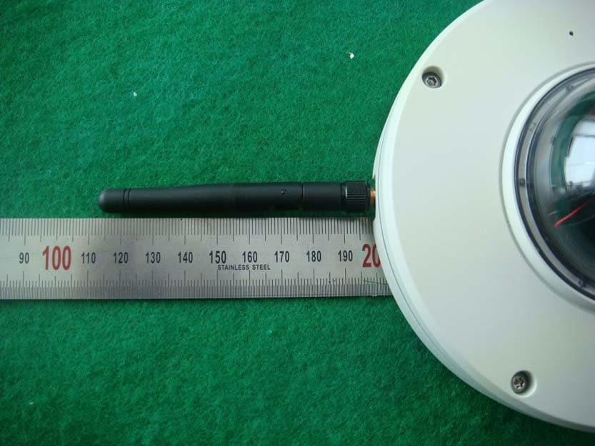
LLINVT72
Mar 11, 2014Network Dome Camera
Equipment Class
DTS - Digital Transmission System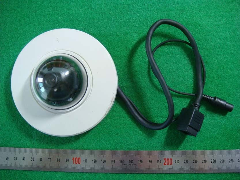
LLINDT72
Sep 29, 2013Network Dome Camera
Equipment Class
DTS - Digital Transmission System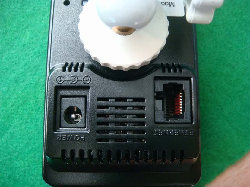
LLINCT525
Dec 11, 2012Cube Network Camera
Equipment Class
DTS - Digital Transmission System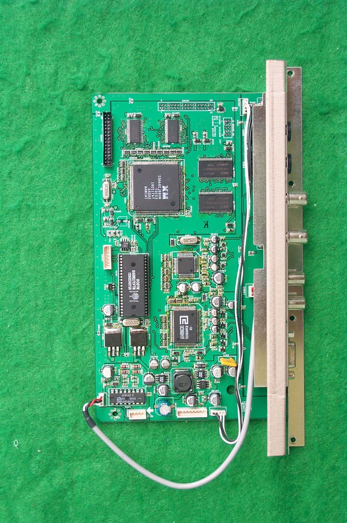
LLIHTM190C
Jul 20, 2003LCD MONITER
Equipment Class
JBP - Part 15 Class B Computing Device Peripheral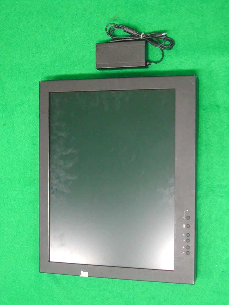
LLIHTM201C
Nov 20, 2002LCD Monitor
Equipment Class
JBP - Part 15 Class B Computing Device Peripheral