LLINVT72Network Dome Camera
Hi Tron Systems Inc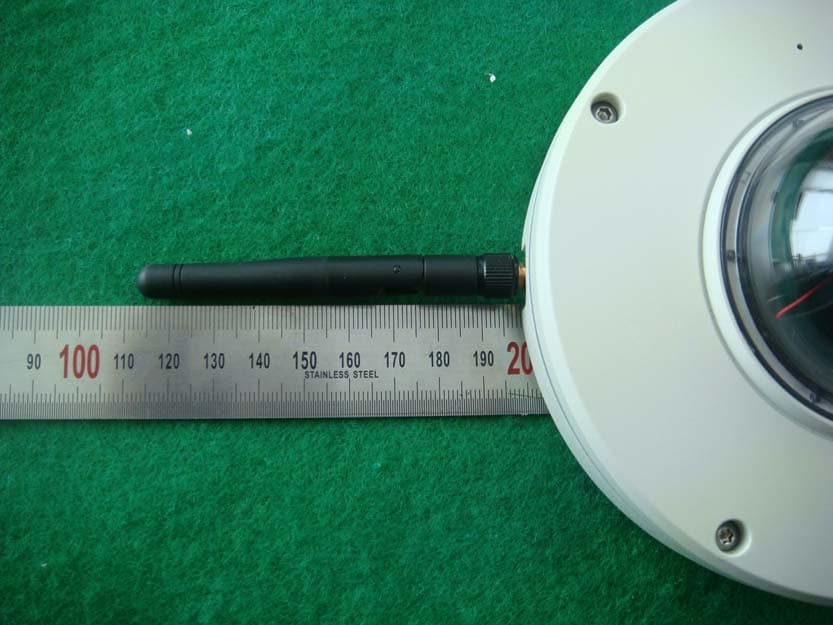
Click to zoom
Application Details
- Equipment Class
- DTS - Digital Transmission System
- Date of Grant
- Mar 11, 2014
- Application Purpose
- Original Equipment
- Date of Application
- Mar 11, 2014
- Equipment Note
- Network Dome Camera
- Frequency Range
- 2422.00000000 - 2452.00000000
- Company
- Hi Tron Systems Inc
- Country
- South Korea
Documents & Files
Document Text
Text extracted from the exhibit documents filed with the FCC. Open a document above to read the original.
Users Manual
PT Mini Dome Full HD Network Camera INSTRUCTION MANUAL Please read this manual thoroughly before use, and keep it handy for future reference. 2 WARNING TO REDUCE THE RISK OF FIRE OR ELECTRIC SHOCK, DO NOT EXPOSE THIS PROCUCT TO RAIN OR MOISTURE. DO NOT INSERT ANY METALLIC OBJECT THROUGH THE VENTILATION GRILLS OR OTHER OPENNINGS ON THE EQUIPMENT. CAUTION EXPLANATION OF GRAPHICAL SYMBOLS The lightning flash with arrowhead symbol, within an equilateral triangle, is intended to alert the user to the presence of uninsulated "dangerous voltage" within the product’s enclosure that may be of sufficient magnitude to constitute a risk of electric shock. The exclamation point within an equilateral triangle is intended to alert the user to the presence of important operating and maintenance (servicing) instructions in the literature accompanying the appliance. PRECAUTIONS Safety -------------------------------------- Installation ------------------------------- Should any liquid or solid object fall into the cabinet, unplug the unit and have it checked by the qualified personnel before operating it any further. Unplug the unit from the wall outlet if it is not going to be used for several days or more. To disconnect the cord, pull it out by the plug. Never pull the cord itself. Allow adequate air circulation to prevent internal heat build-up. Do not place the unit on surfaces (rugs, blankets, etc.) or near materials(curtains, draperies) that may block the ventilation holes. Height and vertical linearity controls located at the rear panel are for special adjustments by qualified personnel only. Do not install the unit in an extremely hot or humid place or in a place subject to excessive dust, mechanical vibration. The unit is not designed to be waterproof. Exposure to rain or water may damage the unit. Cleaning --------------------------------- Clean the unit with a slightly damp soft cloth. Use a mild household detergent. Never use strong solvents such as thinner or benzene as they might damage the finish of the unit. Retain the original carton and packing materials for safe transport of this unit in the future. 3 FCC COMPLIANCE STATEMENT FCC INFORMATION: THIS EQUIPMENT HAS BEEN TESTED AND FOUND TO COMPLY WITH THE LIMITS FOR A CLASS B DIGITAL DEVICE, PURSUANT TO PART 15 OF THE FCC RULES. THESE LIMITS ARE DESIGNED TO PROVIDE REASONABLE PROTECTION AGAINST HARMFUL INTERFERENCE IN A RESIDENTIAL INSTALLATION. THIS EQUIPMENT GENERATES, USES AND CAN RADIATE RADIO FREQUENCY ENERGY AND, IF NOT INSTALLED AND USED IN ACCORDANCE WITH THE INSTRUCTIONS, MAY CAUSE HARMFUL INTERFERENCE TO RADIO COMMUNICATIONS. HOWEVER, THERE IS NO GUARANTEE THAT INTERFERENCE WILL NOT OCCUR IN A PARTICULAR INSTALLATION. IF THIS EQUIPMENT DOES CAUSE HARMFUL INTERFERENCE TO RADIO OR TELEVISOION RECEPTION, WHICH CAN BE DETERMINED BY TURNING THE EQUIPMENT OFF AND ON, THE USER IS ENCOURAGED TO TRY TO CORRECT THE INTERFERENCE BY ONE OR MORE OF THE FOLLOWING MEASURES: -- REORIENT OR RELOCATE THE RECEIVING ANTENNA. -- INCREASE THE SEPARATION BETWEEN THE EQUIPMENT AND RECEIVER. -- CONNECT THE EQUIPMENT INTO AND OUTLET ON A CIRCUIT DIFFERENT FROM THAT TO WHICH THE RECEIVER IS CONNECTED. -- CONSULT THE DEALER OR AND EXPERIENCED RADIO/TV TECHNICIAN FOR HELP CAUTION: CHANGES OR MODIFICATIONS NOT EXPRESSLY APPROVED BY THE PARTY RESPONSIBLE FOR COMPLIANCE COULD VOID THE USER'S AUTHORITY TO OPERATE THE EQUIPMENT. THIS CLASS B DIGITAL APPARATUS COMPLIES WITH CANADIAN ICES-003. CET APPAREIL NUMÉRIQUE DE LA CLASSE B EST CONFORME À LA NORME NMB-003 DU CANADA. TO COMPLY WITH RF EXPOSURE COMPLIANCE REQUIREMENTS, THE ANTENNA USED FOR THIS TRANSMITTER MUST BE INSTALLED TO PROVIDE A SEPARATION DISTANCE OF AT LEAST 20cm (7.9in) FROM ALL PERSONS AND MUST NOT BE CO-LOCATED OR OPERATING IN CONJUNCTION WITH ANY OTHER ANTENNA OR TRANSMITTER. 4 THIS DIGITAL EQUIPMENT FULFILLS THE REQUIREMENTS FOR RF EMISSION ACCORDING TO THE CLASS B LIMIT OF EN 55022. THIS PRODUCT FULFILLS THE REQUIREMENTS FOR IMMUNITY ACCORDING TO EN 55024 OFFICE AND COMMERCIAL ENVIRONMENTS. HEREBY, HITRON SYSTEMS DECLARES THAT THIS PRODUCT IS IN COMPLIANCE WITH THE ESSENTIAL REQUIREMENTS AND OTHER RELEVANT PROVISIONS OF DIRECTIVE 1999/5/EC. A COPY OF THE ORIGINAL DECLARATION OF CONFORMITY MAY BE OBTAINED FROM HITRON SYSTEMS, 5953-85, SEODONG-DAERO, SAMJUGMYEON, ANSEONG-SI, KYUNGGI-DO, KOREA TO COMPLY WITH RF EXPOSURE COMPLIANCE REQUIREMENTS, THE ANTENNA USED FOR THIS TRANSMITTER MUST BE INSTALLED TO PROVIDE A SEPARATION DISTANCE OF AT LEAST 20cm (7.9in) FROM ALL PERSONS AND MUST NOT BE CO-LOCATED OR OPERATING IN CONJUNCTION WITH ANY OTHER ANTENNA OR TRANSMITTER. CAUTION RISK OF EXPLOSION IF BATTERY IS REPLACED BY AN INCORRECT TYPE. DISPOSE OF USED BATTERIES ACCORDING TO THE INSTRUCTIONS. 5 IMPORTANT SAFETY INSTRUCTIONS 1. Read these instructions. 2. Keep these instructions. 3. Heed all warnings. 4. Follow all instructions. 5. Do not use this apparatus near water. 6. Clean only with dry cloth. 7. Do not block any ventilation openings. Install in accordance with the manufacturer’s instructions. 8. Do not install near any heat sources such as radiators, heat registers, stoves, or other apparatus (including amplifiers) that produce heat. 9. Do not defeat the safety purpose of the polarized or grounding-type plug. A polarized plug has two blades with one wider than the other. A grounding type plug has two blades and a third grounding prong. The wide blade or the third prong are provided for your safety. If the provided plug does not fit into your outlet, consult an electrician for replacement of the obsolete outlet. 10. Protect the power cord from being walked on or pinched particularly at plugs, convenience receptacles, and the point where they exit from the apparatus. 11. Only use attachments/accessories specified by the manufacturer. 12. Use only with the cart, stand, tripod, bracket, or table specified by the manufacturer, or sold with the apparatus. When a cart is used, use caution when moving t…
Text truncated - open the document above for the full version.
Cover Letter(s)
HITRON SYSTEMS INC. 5953-85, SEODONG-DAERO, SAMJUG-MYEON, ANSEONG-SI, GYEONGGI-DO, KOREA TEL: +82-31-670-9087, FAX: +82-31-674-4318 http://www.hitron.co.kr/ February 21, 2014 Federal Communications Commission Equipment Authorization Division, Application Processing Branch 7435 Oakland Mills Road Columbia, MD21046 RE: LETTER OF AGENT AUTHORIZATION We, the undersigned, hereby authorize SK TECH Co., Ltd.(Mr. Jongsoo, Yoon) to act on our behalf in all matters relating to application for equipment authorization. We also hereby certify that no party to the application authorized hereunder is subject to the denial of benefits, including FCC benefits, pursuant to Section 5301 of the Anti-Drug Abuse Act of 1988, 21 U.S.C.853(a). APPLICANT/AGENT CERTIFICATION AND AGREEMENT: All of the statements herein and the exhibits attached hereto, are true and correct to the best of my knowledge and belief. In accepting a Grant of Equipment Authorization issued by the TCB, under the authority of the FCC, as a result of the representations made in this application, the applicant is responsible for (1) labeling the equipment with the exact FCC ID specified in this application, (2) compliance statement labeling pursuant to the applicable rules, and (3) compliance of the equipment with the applicable technical rules. If the applicant is not the actual manufacturer of the equipment, appropriate arrangements have been made with the manufacturer to ensure that production units of this equipment will continue to comply with the FCC’s technical requirements. Authorizing an agent to sign this application, is done solely at the applicant’s discretion; however, the applicant remains responsible for all statements in this application. Sincerely, Seong-kon, Kim/ General Manager
Cover Letter(s)
HITRON SYSTEMS INC. 5953-85, SEODONG-DAERO, SAMJUG-MYEON, ANSEONG-SI, GYEONGGI-DO, KOREA TEL: +82-31-670-9087, FAX: +82-31-674-4318 http://www.hitron.co.kr/ February 21, 2014 Federal Communications Commission Equipment Authorization Division, Application Processing Branch 7435 Oakland Mills Road Columbia, MD21046 TO WHOM IT MAY CONCERN ATTESTATION: We, the undersigned, would like to declare that the composite portion categorized as Class B digital device has been authorized under the Verification procedure. FCC ID Number Product Description (Model) LLINVT72 Network Dome Camera(NVT-7202) Sincerely, Seong-kon, Kim/ General Manager
Cover Letter(s)
HITRON SYSTEMS INC. 5953-85, SEODONG-DAERO, SAMJUG-MYEON, ANSEONG-SI, GYEONGGI-DO, KOREA TEL: +82-31-670-9087, FAX: +82-31-674-4318 http://www.hitron.co.kr/ February 21, 2014 Federal Communications Commission Equipment Authorization Division, Application Processing Branch 7435 Oakland Mills Road Columbia, MD21046 TO WHOM IT MAY CONCERN Pursuant to Paragraphs §0.457 and 0.459 of the Commission's Rules (47 C.F.R) and Section §552(b)(4) of the Freedom of Information Act, HITRON SYSTEMS INC. requests confidentiality for the following products: FCC ID Number Product Description (Model) LLINVT72 Network Dome Camera(NVT-7202) The requested Permanent and Short-Term Confidential exhibits art listed as follows: PERMANENT AND SHORT-TERM CONFIDENTIAL LIST Exhibit Description PERMANENT 1 Block Diagram 2 Operational Description 3 Schematics 4 Part List No other items submitted as part of the equipment authorization filing process are deemed confidential. The above exhibits contain HITRON SYSTEMS INC. trade secrets and proprietary information that could be of benefit to our competitors regarding the design of our products. This material is not customarily available to the general public and we request that it be withheld from public inspection. Sincerely, Seong-kon, Kim/ General Manager
External Photos
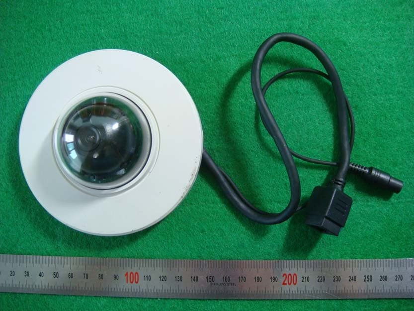
SK Tech Co., Ltd. Page 1 of 3 Photographs of EUT External view SK Tech Co., Ltd. Page 2 of 3 SK Tech Co., Ltd. Page 3 of 3 WLAN Antenna
ID Label/Location Info
ID Label Location & Sample LABEL LOCATION: LABEL will be attached to the bottom of the product LABEL Drawing:
Internal Photos
SK Tech Co., Ltd. Page 1 of 6 Photographs of EUT Cover opened SK Tech Co., Ltd. Page 2 of 6 Main board WLAN Module SK Tech Co., Ltd. Page 3 of 6 Camera module SK Tech Co., Ltd. Page 4 of 6 Camera module board SK Tech Co., Ltd. Page 5 of 6 Power board SK Tech Co., Ltd. Page 6 of 6 WLAN Module Board
Test Report
Report No.: SKT-RFC-140002 Page 1 of 38 FCC RF TEST REPORT Test Laboratory: Test Report Number: SKT-RFC-140002 SK Tech Co., Ltd. 820-2, Wolmoon-ri, Wabu-up, Namyangju-si, Kyunggi-do 472-905 South Korea TEL: +82-31-576-2204 FAX: +82-31-576-2205 Date of issue: February 21, 2014 Applicant: HITRON SYSTEMS INC. 5953-85, SEODONG-DAERO, SAMJUG-MYEON, ANSEONG-SI, GYEONGGI-DO, KOREA Manufacturer: HITRON SYSTEMS INC. 5953-85, SEODONG-DAERO, SAMJUG-MYEON, ANSEONG-SI, GYEONGGI-DO, KOREA Product: Network Dome Camera Model: NVT-7202 (please see P5 for all the model numbers) FCC ID: LLINVT72 File number: SKTEU13-1551 EUT received: January 29, 2014 Applied standards: ANSI C63.10-2009 and ANSI C63.4-2009 558074 D01 DTS Meas Guidance v03r01 Rule parts: FCC Part 15 Subpart C - Intentional radiators Equipment Class: DTS - Part 15 Digital Transmission System Remarks to the standards: None The above equipment has been tested by SK Tech Co., Ltd., and found compliance with the requirements set forth in the technical standards mentioned above. The results of testing in this report apply only to the product or system, which was tested. Inyong Song / Testing Engineer Jongsoo Yoon / Technical Manager This report shall not be reproduced except in full, without the written approval of SK Tech Co., Ltd. The client should not use it to claim product endorsement by any government agencies. SK Tech Co., Ltd. Report No.: SKT-RFC-140002 Page 2 of 38 Revision History of Report Rev. Revisions Effect page Reviewed by Date - Initial issue All Jongsoo Yoon February 21, 2014 SK Tech Co., Ltd. Report No.: SKT-RFC-140002 Page 3 of 38 TABLE OF CONTENTS 1 Summary of test results ................................................................................................. 4 2 Description of equipment under test (EUT) .................................................................. 5 3 Test and measurement conditions ................................................................................ 6 3.1. Test configuration (arrangement of EUT) ................................................................................ 6 3.2. Description of support units (accessory equipment)................................................................ 6 3.3. Interconnection and I/O cables................................................................................................ 6 3.4. Measurement Uncertainty (U) ................................................................................................. 6 3.5. Test date .................................................................................................................................. 6 4 Facilities and accreditations .......................................................................................... 7 4.1. Facilities................................................................................................................................... 7 4.2. Accreditations .......................................................................................................................... 7 4.3. List of test and measurement instruments............................................................................... 7 5 Test and measurements ................................................................................................. 8 5.1. Antenna requirement ............................................................................................................... 8 5.2. Test Configuration of Equipment Under Test ........................................................................... 9 5.3. 6 dB bandwidth...................................................................................................................... 10 5.4. Maximum peak output power ................................................................................................ 13 5.5. Spurious emissions, Band edge, and Restricted bands ........................................................ 16 5.6. Peak power spectral density.................................................................................................. 33 5.7. AC power line conducted emissions...................................................................................... 36 SK Tech Co., Ltd. Report No.: SKT-RFC-140002 Page 4 of 38 1 Summary of test results Requirement CFR 47 Section Result Antenna Requirement 15.203, 15.247(b)(4) Meets the requirements 6dB Bandwidth 15.247(a)(2) Meets the requirements Maximum Peak Output Power 15.247(b)(3), (4) Meets the requirements Spurious Emission, Band Edge, and Restricted bands 15.247(d), 15.205(a), 15.209(a) Meets the requirements Peak Power Spectral Density 15.247(e) Meets the requirements AC power line Conducted emissions 15.207(a) Meets the requirements SK Tech Co., Ltd. Report No.: SKT-RFC-140002 Page 5 of 38 2 Description of equipment under test (EUT) Product: Network Dome Camera Model: NVT-7202 Serial number: None (prototype) Model differences: Model name Difference Tested (checked) NVT-7202 Original (basic model that was fully tested) 2M-PTD3W GND20L-VW Listed by the applicant's request without the tests; the applicant declared that the variant models were identical to the tested sample and added for the marketing purpose Note: All the differences were compared with the test sample Technical data: Power source DC 12 V Local Oscillator or X-Tal XTAL: 32.768 kHz, 24 MHz, 25 MHz, 37.125 MHz (WLAN module) 40 MHz Transmit Frequency IEEE 802.11b: 2412 MHz ~ 2462 MHz (11 channels) IEEE 802.11g: 2412 MHz ~ 2462 MHz (11 channels) IEEE 802.11n HT20: 2412 MHz ~ 2462 MHz (11 channels) IEEE 802.11n HT40: 2422 MHz ~ 2452 MHz (7 channels) Antenna Type Whip antenna (reverse polarity SMA type, peak gain : 2.1 dBi) Type of Modulation IEEE 802.11b: DSSS (DBPSK, DQPSK, CCK) IEEE 802.11g/n HT20/40: OFDM(64QAM, 16QAM, QPSK, BPSK) RF Output power 20.63 dBm PEAK (measured) NOTE The test report for the compliance with FCC Part 15B as a digital device was issued with other t…
Text truncated - open the document above for the full version.
Test Setup Photos
SK Tech Co., Ltd. Report No.: SKTEFC-130913-013 Page 1 of 4 Photographs of the test set-up Radiated emissions - front view Radiated emissions - rear view SK Tech Co., Ltd. Report No.: SKTEFC-130913-013 Page 2 of 4 Radiated emission test below 30 MHz Radiated emission test below 1 GHz SK Tech Co., Ltd. Report No.: SKTEFC-130913-013 Page 3 of 4 Radiated emission test above 1 GHz SK Tech Co., Ltd. Report No.: SKTEFC-130913-013 Page 4 of 4 AC Power line conducted emissions - front view AC Power line conducted emissions - rear view
Contact Information
Applicant
Seong-kon Kim(General Manager, CS Team)
Test Firm
SK Tech Co., LTD.Yoon Jongsoo
Technical Specifications
| # | Rule Parts | Frequency Range | Power Output |
|---|---|---|---|
| 2 | 15C | 2.42 GHz - 2.45 GHz | 64.00 mW |
Other Applications from Hi Tron Systems Inc
LLINDT72
Sep 29, 2013Network Dome Camera
Equipment Class
DTS - Digital Transmission System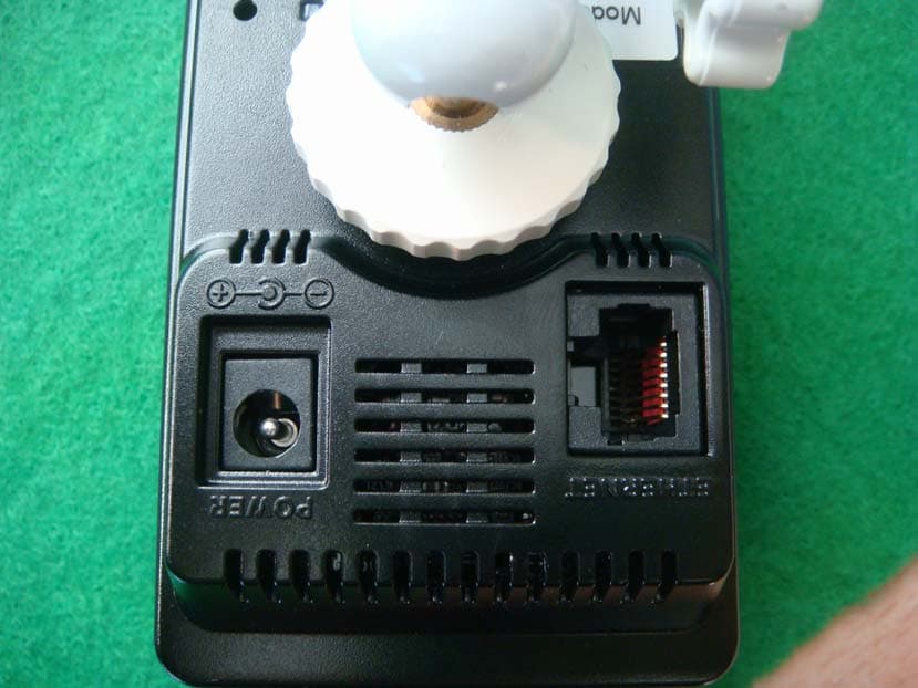
LLINCT525
Dec 11, 2012Cube Network Camera
Equipment Class
DTS - Digital Transmission System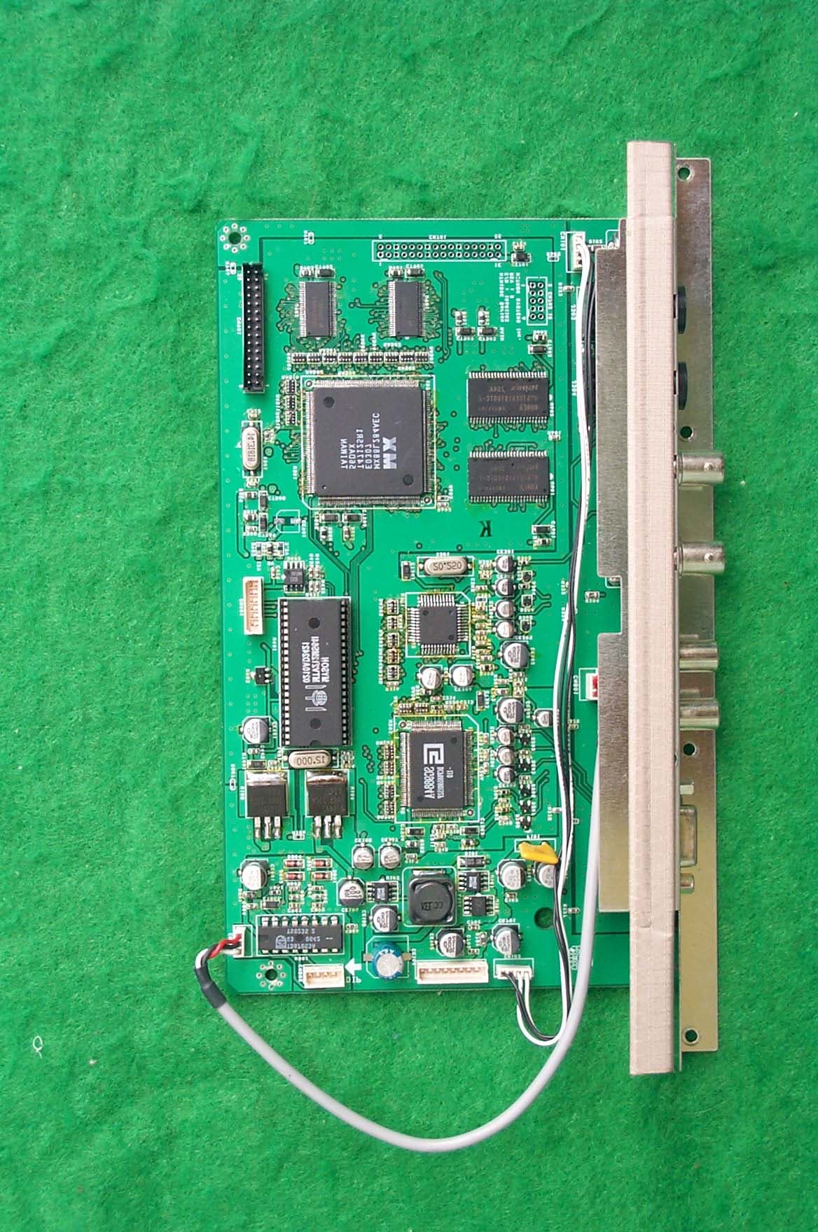
LLIHTM190C
Jul 20, 2003LCD MONITER
Equipment Class
JBP - Part 15 Class B Computing Device Peripheral
LLIHTM170B
May 27, 2003LCD Monitor
Equipment Class
JBP - Part 15 Class B Computing Device Peripheral
LLIHTM201C
Nov 20, 2002LCD Monitor
Equipment Class
JBP - Part 15 Class B Computing Device Peripheral