LNQ-802CIPCMCIA transceiver
Actiontec Electronics Inc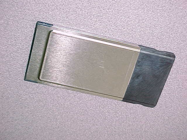
Click to zoom
Application Details
- Equipment Class
- DSS - Part 15 Spread Spectrum Transmitter
- Date of Grant
- Mar 22, 2001
- Application Purpose
- Original Equipment
- Date of Application
- Mar 22, 2001
- Equipment Note
- PCMCIA transceiver
- Frequency Range
- 2400.00000000 - 2483.50000000
- Company
- Actiontec Electronics Inc
- Country
- United States
Documents & Files
Document Text
Text extracted from the exhibit documents filed with the FCC. Open a document above to read the original.
Users Manual
802CI User Manuel 2 Contents 1. Contents 2. Introduction 3. Wireless LAN Basics 4. Installation for Window 95 / 98 5. Troubleshooting 6. Technical specifications of 802CI 3 2. Introduction Thank you for purchasing your Wireless LAN, 802CI PC Card. This manual will assist you with the installation procedure. The package you have received should contain the following items: • 802CI PC Card • User manual • Diskette containing Wireless LAN Management utility and drivers Note: if anything is missing, please contact your vendor The diskette contains the drivers and the program; this is used for managing the 802CI card and establishing the wireless connection with your Local Area Network. 4 3. Wireless LAN Basics Wireless LAN (Local Area Networks) systems offer a great number of advantages over a traditional, wired system. Wireless LANs (WLANs) are more flexible, easier to setup and manage and often more cost effective than their wired equivalence. Using radio frequency (RF) technology. WLANs transmit and receive data over the air, minimizing the need for wired connections. Thus, WLANs combine data connectivity with user mobility, and, through simplified configuration, enable movable LANs. With wireless LANs, users can access shared information without looking for a place to plug in and network managers can set up or augment networks without installing or moving wires. Wireless LANs offer the following productivity, convenience and cost advantages over traditional wired networks. • Mobility – Wireless LAN systems can provide LAN users with access to real-time information anywhere in their organization. This mobility supports productivity and service opportunities not possible with wired networks. • Installation Speed and Simplicity – Installing a wireless LAN system can be fast and easy and can eliminate the need to pull cable through walls and ceilings. • Installation Flexibility – wireless technology allows the network to go where wires cannot go. • Reduced Cost-of-Ownership – While the initial investment required for wireless LAN hardware might be higher than the cost of wired LAN hardware, overall installation expenses and life-cycle costs will be significantly lower. Long- term cost benefits are greatest in dynamic environments requiring frequent moves, adds, and changes. • Scalability – Wireless LAN systems can be configured in a variety of topologies to meet the needs of specific applications and installations. Configurations are easily changed and range from peer-to-peer networks suitable for a small number of users to full infrastructure networks of thousands of users that allows roaming over a broad area. 5 4. Installation for Windows 95 / 98 The following section will assist you to installing wireless LAN Adapter successfully. You will first install software (driver) and then insert the 802CI wireless LAN card, and finally set the network properties to accommodate resource sharing and select the type of wireless network that you wish to install. The 802CI can be easily be installed and used, without bothering to connect cables for keeping your computer to use network resources, as in case of wired LAN. 6 4.1 Installation Overview Here are some steps you will perform in establishing your wireless network connection: • Install the Access Point at first. AP is needed in case of Infrastructure network mode. • Install the software using the Installation Diskette. • Install the Wireless LAN Card (802CI). • Install the network protocol(s) required to communicate on your network. Most likely you will need the TCP/IP protocol. 7 4.2 Installation Procedure of 802CI PC Card Note: Do not insert the PCMCI card until you are asked to do so, failure of which may result in unsuccessful installation of your PCMCIA WLAN card. Please follow the following steps one by one in order to install the PCMCIA card successfully. 1. Power on your computer and allow Windows 95 / 98 to load fully. 2. Be sure that there is no PCMCIA adapter inserted yet. 3. Insert the given Installation Diskette and then click on the A:\disk1\setup.exe. 4. Accept the license agreement. 5. Give the path of the destination folder. To set the path of your choice click on Browser and then click Next. 6. It takes a few seconds for copying the utility files and then click on Finish to complete the installation. 7. Insert the 802CI card into PCMCIA slot; windows will then prompt the required driver. 8. Locate the driver path Ex. A:\ and install the driver 9. Restart the PC and Click on the Control Panel and then on PC Card. Check whether it has PCMCIA card in one of the sockets or not. If you find 802CI PC Card in one of the sockets, it means the card is detected properly. 10. Check for the 802CI Wireless PCMCIA LAN Card by right clicking on My Computer using the mouse. Select the Device manager and then Network Adapters. If you find the sign on the adapter, it shows the installation is not successful. Select the adapter and click on Remove. Restart your computer after uninstalling the driver to make the changes effective. And refer to manual. 11. Right click on the Network Neighborhood using the mouse. 12. Select Properties from the pop up menu. The network box appears and you see the three main tables: Configuration, Identification, and Access Control. 13. Click on the Configuration tab and then click on the Add button. Select Network Component Type box appears. Click on the Protocol the click the Add button. 14. Select Network Protocols box appears. From the list of manufactures, click on Microsoft. From the list of network protocols list, select NetBEUI, then click OK. 15. The NetBEUI protocol is now installed. After clicking on OK return back to Network Component Type box. 16. Repeat the step 15 and 16 to add IPX/SPX protocol. 17. Repeat the step 15 and 16 to add TCP/IP protocol. 18. Click on the TCP/IP option for setting the IP address for your computer. You can select either Static OR DHCP setting. If you use the static IP setup th…
Text truncated - open the document above for the full version.
Cover Letter(s)
Response to TCB questions Email dated 2/9/2001 Hi Alice, We have conducted our review of the application and the following issues need to be resolved before can proceed: 1. The bandwidth plot on page 9 of the test report is illegible. Please provide a higher resolution plot. Answer: New test report supplied 2. The ETS test on page 10 of the test report does not appear to measure the correct parameter. We need to know the total transmit power of the actual spread spectrum signal. Measurement of a sinusoid at the same frequency will not give us this result. Please provide measurement data for the actual spread spectrum output. Per 15.31(m) provide these measurements for three channels (high, middle, low). Answer: New test report supplied 3. Page 13 of the test report does not document compliance with the requirements on conducted spurious emissions. Please provide data which documents that the conducted spurious emissions are at least 20 dB below the carrier over the range of 30MHz to 24.5GHz. You will need to expand the measurement range and provide data at on the fundamental signal level observed. Answer: New test report supplied 4. The peak power density on page 16 is performed using an ETSI test method which does not appear to comply with the FCC requirements and does not appear to demonstrate compliance with the FCC requirements. Please provide data responsive to the FCC requirement that power be less than 8dBm in any 3kHz band (15.247(d)) using the FCC test methods attached. Answer: New test report supplied 5. Please confirm that the LISN used for line conducted measurements was a 50 Ohm/50uH unit. Answer: New test report supplied 6. The readings shown on page 23 of the test report fail the FCC limits of 15.209. The corrected limit at 10 meters at 442MHz and 344 MHz is 35.5dBuV/m. The data shows 35.8dBuV/m which fails by 0.2dB. As notes to the table indicate that these emissions were believed to be sourced by the laptop, we suggest that you retest your unit in a compliant laptop and submit data which documents compliance. Answer: New test report supplied 7. Please provide data responsive to the voltage stability requirements of 15.31(e) Answer: New test report supplied 8. Please provide a discussion of how the US user is prevented from accessing the three higher frequency EU channels. No answer 9. Radiated emissions were only provided for the range 30-1000MHz. Please provide radiated emissions measurements for the required range of 30MHz-24.8MHz in accordance with 15.33(a). Answer: New test report supplied. 10. We need a detailed description of the DSS process. What is the chip rate? Symbol rate? Spreading rate? The report seems to be confused as to if this is a DSS or a frequency hopping system or a hybrid. What is this unit? Answer: New test report supplied 11. What is the antenna gain? Since it is a PC trace an estimate will be acceptable. Answer: New test report supplied 12. We need data documenting compliance with the processing gain requirements. Provide both theoretical and measurement based analysis. See attached jamming margin test procedure. Answer: New test report supplied 13. Please provide an exhibit discussing the units MPE compliance and establishing the minimum separation distance for RF exposure compliance. Answer: New test report supplied 14. You may wish to review our TCB checklist on spread spectrum transmitters to ensure that you have addressed all issues. A copy is attached. 15. Please supply details of the label material. Answer: The label material is polyester. Best regards Barry C. Quinlan Certification & Telecom Manager Curtis-Straus LLC Email dated 2/22/2001 Hi Alice, We have reviewed the new data you provided and the following issues were found: 1. You have claimed a power output of 0.1 Watts on the form 731, 0.5 watts on page 2 of the test report, and have provided data which shows a 0.01 watt power output. Please explain this factor of ten (or fifty) deviation between claimed power output and measured power output. Answer: a revised 731 and report are reflect the output power. 0.02W (max.) 2. Please confirm that the LISN was a 50 Ohm/ 50uH device. From the new data we see a claim that it is 50 Ohms. Please tell us the nominal value of the inductive element. Answer: LISN schematics is included in the revised test report. 3. Please provide data responsive to the voltage variation requirement of 15.31(e). Answer: EUT has retest for voltage variation early this morning data are included in the test report. 4. Please provide a discussion of how the US user is prevented from accessing the three higher frequency EU channels. Answer: There is a piece of data stored in the card (flash memory) called zone information to indicate where this card will be sold. The program in this card will look at the zone information for the available channel for end user. For the 802CI sold in U.S. & Canada, the zone information will be north America, which only allow user to use from channel 1 to 11. 5. Please tell us why processing gain data for the Intersil HWB3163 Rev B WLAN PCMCIA card has been provided. Is this device identical to the Actiontec LNQ-802CI? If so, please make a statement to that effect. Answer: 802CI and Intersil HWB3163 Rev B WLAN PCMCIA card is very similar. Both card use the same chipset (Intersil Prism 2 chipset) & firmware. The 802CI board layout is referred from HWB3163 Rev B WLAN PCMCIA card with very minor modification, such as changing the flash chip footprint so that alternative flash chip source can be used. Processing gain will be the same. 6. Please provide an exhibit discussing the devices MPE RF exposure compliance and establishing the minimum separation distance for this device. A statement will need to be inserted in the user manual regarding RF exposure. We will advise you on the wording when the RF power output issue is resolved and you supply the MPE data. Answer: 802CI is a PCMCIA Wireless LAN card, it is mostly used in PC system either de…
Text truncated - open the document above for the full version.
External Photos
ActionTec Electronic, Inc. FCC ID #: LNQ-802CI Test Report #: ACT-0008-2667-FCC Prepared for ActionTec Electronics, Inc. Prepared by EMC Compliance Management GroupPage 25 of 26 ATTACHMENT M – SAMPLE PHOTOS
ID Label/Location Info
ActionTec Electronic, Inc. FCC ID #: LNQ-802CI Test Report #: ACT-0008-2667-FCC Prepared for ActionTec Electronics, Inc. Prepared by EMC Compliance Management GroupPage 26 of 26 ATTACHMENT N – PROPOSED FCC ID LABELS AND LOCATION ATTACHMENT O – PLOTS OF TESTS ATTACHMENT P – PROCESSING GAIN Proposed FCC ID Location FCC ID #: LNQ802CI
ID Label/Location Info
This device complies with part 15 of the FCC rules. Operation is subject to the following2 conditions: (1) This device may not cause harmful interference, and (2) this device must accept any interference received, including interference that may cause undesired operation. ACTIONTEC 802CIFCC ID LNQ-802CI
Internal Photos
FCC ID: LNQ-802CI Internal photos
Operational Description
1 Method of Operation The 802CI products are self contained 2.4Ghz ISM Band Radios. These radios are designed to operate using the 802.11B Wireless LAN Standard for use in Wireless Networking systems. The Radio consists of 5 Major IC’s (HFA3983, HFA3683, HFA3783, HFA3683, and HFA3841) in the radio section and 3 other support IC’s and it operates in a Half-Duplex mode using the CSMA/CA (Carrier Sense Multiple Access/Collision Avoidance) principle. The radio card interfaces to the PC via a PCMCIA interface. Receive Path The receive signal traveling through the air is received by one of the dual diversity antennas. The circuit will switch to the antenna which provides the best reception and strongest signal power. The RF signal then feeds into the 85MHz BW filter and through the Transmit/Receive switch. Then the signal is amplified using the LNA within the HFA3683 and mixed-down to an IF frequency of 374 MHz. The PLL and Synthesizer in the HFA3683 selects the Channel frequency for operation using Low Side Injection. The output of the Mixer in the HFA3683 is shared with the transmit path using a switch. The signal then flows through a image rejection SAW filter which has a 3db bandwidth of 17Mhz. The signal then flows into the HFA3783 Quad IF Downconverter IC, through a two stage Analog AGC circuit which adjusts the gain to compensate for signal gain differences. The output of the Twin AGC’s provide a constant signal level to the I and Q Conversion/Downconversion mixers, which convert both the I & Q signals to Baseband. A second Frequency Synthesizer feeds the Twin I & Q mixers with the same frequency signal that is phase shifted by 90 degrees. The output of the twin I & Q mixers then flows into a Dual Active 5 th Order Butterworth filter to remove the anti- aliasing components and Images from the down- converted signal. The twin I & Q signals then flow into the HFA3863 Baseband processor and are converted into digital signals via the dual A/D converters then flow through the digital AGC followed by the Digital Demodulator. The output of the digital demodulator is sent into a I/O interface of the HFA3841 MAC(Media Access Controller). The Received signal then flows into the Phy I/O interface and into the MAC protocol engine. The HFA3841 MAC converts the signal protocol from 802.11B to 802.3 Ethernet then passes that data through the HOST I/O PCMCIA interface to the PC. The transmit signal path is as follows; Transmit Path The Ethernet data passes from the PC to the HFA3841 MAC, to the Host I/O interface through the PC CARD. The signal then flows into the Data router where it is converted from the Ethernet to 802.11B protocol. After the signal is converted, a radio preamble and Header is added to the signal and passed to the radio I/O. There is also support circuitry for WEP encryption and the outboard SRAM and flash ROM, which contains the firmware which controls the radio. The signal then flows from the HFA4841 into the HFA3783 as both I & Q signals into the dual Up conversion mixers. Then, the signal upconverts to a IF frequency of 374 MHz and passes into a variable gain amplifier. Next, it passes through the Switched Shared SAW filter into the HFA3683 and then upconverts to a RF frequency from 2.4GHz to 2.485 GHz, depending on the channel selection. The signal then flows through a external Image reject filter, pre-amplifier, and then through a second Pulse shaping filter into the HFA3983 Power amplifier. The output of the power amplifier is then feed through the Transmit/Receive switch, then through bandpass filter with a pass bandwidth of 85MHz, then finally through the strongest signal selected antenna.
RF Exposure Info
ActionTec Electronic, Inc. FCC ID #: LNQ-802CI Test Report #: ACT-0008-2667-FCC Prepared for ActionTec Electronics, Inc. Prepared by EMC Compliance Management GroupPage 13 of 46 ATTACHMENT H – CFR15.247(b)(4) RF EXPOSURE COMPLIANCE RF energy generated by EUT shall meet CFR1.1307 (b)(1) guideline. RADIATED PEAK POWER MAXIMUM CONDUCTED OUTPUT ANTENNA GAIN (dBm/m)(dBm)(dBi) 11.99.82.1 ANTENNA GAIN MAXIMUM CONDUCTED OUTPUT EIRPEIRPMPE DISTANCE MINIMUM ALLOWABLE EXPOSURE SEPARATION DISTANCE (dBi)(dBm)(dBm)(mW)(cm)(cm) 2.19.811.915.5<2.120 1. According to FCC Part 2.1091, the EUT should be classified as a mobile device At normal usage results in more than 20cm separation between user and antenna. The Maximum Permissible Exposure (MPE) shown in 47 CFR1.1310 is 1mW/cm 2 for 2.4GHz band. 2. EIRP = P (dB) (Max. Conducted output) + G (dB) (Antenna Gain) 3. MPE distance are based on a conservative “worst case” prediction. Using formula S = EIRP / 4πR 2 and no calculation for duty factor. In practice the minimum distance will be shorter. The following statement will be place in user’s manual: “CAUTION: To comply with FCC RF exposure requirements, a separation distance of at least 8 inches (20cm) must be maintained between the antenna of this and all persons.”
Test Report
EMC Compliance Management Group 670 National Avenue Mountain View, CA 94043 Tel. (650) 988-0900 Fax (650) 988-6647 NVLAP Lab code: 200068-0 FCC PART 15.247 REPORT On Model: 802 CI Prepared for ActionTec Electronics, Inc. According to CFR 15.247 Requirements FCC ID #:LNQ-802CI Test Report #:ACT-0008-2667-FCC Prepared by: Kelly Miguel Page i of 28 Table of Contents DISCLAIMER NOTICE_________________________________________________________1 REPRODUCTION CLAUSE_____________________________________________________1 ADMINISTRATIVE DATA______________________________________________________2 EUT DESCRIPTION___________________________________________________________2 TEST SUMMARY______________________________________________________________3 TEST LOCATION_____________________________________________________________5 ACCREDITATION BODIES_____________________________________________________5 EUT EXERCISE SOFTWARE____________________________________________________6 EQUIPMENT MODIFICATION__________________________________________________6 TEST SYSTEM DETAILS_______________________________________________________6 CONFIGURATION OF TESTED SYSTEM________________________________________7 ATTACHMENT A – PRODUCT INFORMATION__________________________________8 ATTACHMENT B – CFR15.205 RESTRICTED BAND_____________________________9 ATTACHMENT C – CFR15.203 ANTENNA REQUIREMENT____________________10 ATTACHMENT D – CFR 15.247(A)(2) – DIRECT SEQUENCE BANDWIDTH (CONDUCTED)_____________________________________________________________11 ATTACHMENT E – CFR15.247(B) MAXIMUM PEAK OUTPUT POWER MEASUREMENT & CFR15.31(E) VOLTAGE VIRIATION TESTS (CONDUCTED)__12 ATTACHMENT F – CFR15.247(C) RADIATED EMISSION MEASUREMENT 1GHZ - 25GHZ (FUNDAMENTAL AND HARMONICS)_________________________________13 ATTACHMENT F – CFR15.247 (C) RADIATED EMISSION MEASUREMENT 1GHZ - 25GHZ (FUNDAMENTAL AND HARMONICS) (CONT.)_________________________14 ATTACHMENT F – CFR15.247(C) RADIATED EMISSION MEASUREMENT 1GHZ - 25GHZ (FUNDAMENTAL AND HARMONICS) (CONT.)_________________________15 ATTACHMENT G - CFR 15.247(D) POWER DENSITY (CONDUCTED)___________16 ATTACHMENT H –ANTENNA GAIN (ESTIMATED)____________________________17 ATTACHMENT I – CFR15.209(A) RADIATED EMISSION MEASUREMENT 212-R- 01)________________________________________________________________________18 ATTACHMENT J - CFR15.207 (A) CONDUCTED EMISSION TEST RESULTS____20 ATTACHMENT K - TEST EQUIPMENT________________________________________23 ATTACHMENT L – LISN SPECIFICATIONS____________________________________24 ATTACHMENT M – SAMPLE PHOTOS________________________________________25 ATTACHMENT N – PROPOSED FCC ID LABELS AND LOCATION______________26 ATTACHMENT O – PLOTS OF TESTS________________________________________26 ATTACHMENT P – PROCESSING GAIN_______________________________________26 ActionTec Electronic, Inc. FCC ID #: LNQ-802CI Test Report #: ACT-0008-2667-FCC Prepared for ActionTec Electronics, Inc. Prepared by EMC Compliance Management GroupPage 1 of 26 Disclaimer Notice When government drawing, specification, or other data are used for any purpose other than in connection with a definitely related government procurement operation, the United States Government thereby incurs no responsibility nor any obligation whatsoever; and the fact that the Government may have formulated, furnished, or in any way supplied the said drawing, specifications, or other data, is not to be regarded by implication or otherwise in any manner licensing the holder or any other person or corporation, or conveying any rights or permission to manufacture, use, or sell patented invention that may in any way be related thereto. This report must not be used to claim product endorsement by NVLAP or any agency of the U.S. Government. Reproduction Clause Any reproduction of this document must be done in full. No single part of this document may be reproduced without permission from EMC Compliance Management Group, 670 National Ave., Mountain View, CA 94043. ActionTec Electronic, Inc. FCC ID #: LNQ-802CI Test Report #: ACT-0008-2667-FCC Prepared for ActionTec Electronics, Inc. Prepared by EMC Compliance Management GroupPage 2 of 26 Administrative Data Manufacturer: ActionTec Electronics, Inc. 760 N. Mary Avenue Sunnyvale, CA 94086 Telephone: (408) 548-4813 FCC ID: LNQ-802CI Class: Spread Spectrum Transceiver Interface Type: PCMCIA Frequency Range: 2400.0 – 2470.5 MHz Method: Direct Sequence Spread Spectrum System Model Name(s): 802CI Part Number: N/A Max RF Output (W): 0.02 Watts (maximum) Power Supply: Through Host PC CFR Part(s): CFR15.247 Date(s) of Tests: February 11-23, 2001 Report Number: ACT-0008-2667-FCC EUT Description ActionTec Electronic, model 802 CI (referred to as the EUT in this report) is a PCMCIA interface Direct Sequence Spread Spectrum Transceiver. ActionTec Electronic, Inc. FCC ID #: LNQ-802CI Test Report #: ACT-0008-2667-FCC Prepared for ActionTec Electronics, Inc. Prepared by EMC Compliance Management GroupPage 3 of 26 Test Summary Test Summary (CFR 15.247) SpecificationsRequirement ResultsNote CFR15.247(a)(2)For direct sequence systems, the minimum 6dB bandwidth shall be at least 500kHz. CompliedAttachment D CFR15.247(b)(1)For frequency hopping systems operating in the 2400-2483.5 MHz or 5725-5850 MHz band and for all direct sequence systems: 1 watt. CompliedAttachment E CFR15.247(b)(4)Systems operating under the provisions of this section shall be operated in a manner that ensures that the public is not exposed to radio frequency energy levels in excess of the Commission’s guidelines. Ses 1.1307(b)(1) of this chapter. N/AEUT is not a PCS device. CFR15.247(c)In any 100 kHz bandwidth outside the frequency band in which the spread spectrum intentional radiator is operating, the radio frequency power that is produced by the intentional radiator shall be at least 20 dB below that in the 100 kHz bandwidth within the band that contains the highest level of the desired power, base on either an RF conducte…
Text truncated - open the document above for the full version.
Test Report
ActionTec Electronic, Inc. FCC ID #: LNQ-802CI Test Report #: ACT-0008-2667-FCC Prepared for ActionTec Electronics, Inc. Prepared by EMC Compliance Management GroupPage 28 of 74 ATTACHMENT O – PROCESSING GAIN MEASUREMENT Scope This report contains the results of the processing gain testing performed on the ActionTec 802CI Wireless LAN Cards. The tests were carried out in accordance with FCC CFR 15.247(e). The jamming margin method specified in 15.247(e)(2) was used to perform the processing gain testing. Applicable References 1. FCC CFR 15.247(e). 2. FCC 97114 “Guidance on Measurements for Direct Sequence Spread Spectrum Systems”. 3. “Testing for compliance with FCC rules 15-247e” by Carl Andren of Intersil Corporation. FCC Requirements The processing gain of a direct sequence system shall be at least 10dB. The processing gain shall be determined from the ratio in dB of the signal-to-noise ratio with the system spreading code turned off to the signal-to-noise ratio with the system spreading code turned on, as measured at the demodulated output of the receiver. Test Equipment Test EquipmentManufacturer/ ModelSerial No.Last Cal.Cal. Due Date EMI ReceiverR&S / ESMI-RF849937/00603/01/0003/01/01 EMI ReceiverR&S / ESAI-D825035/00503/01/0003/01/01 Signal GeneratorHP / 83711B3324A0328808/29/0008/29/01 Power DividerWeinschel / 1515TEC # 1152602/27/0102/27/02 Directional CouplerWeinschel / 1537RA-20TEC # 2150902/27/0102/27/02 PCASUS / M83000INI006993 PCMicron / 2230# 215 Transmitter (EUT)ActionTec / 802CI#14 Receiver (EUT)ActionTec / 802CIN/A ActionTec Electronic, Inc. FCC ID #: LNQ-802CI Test Report #: ACT-0008-2667-FCC Prepared for ActionTec Electronics, Inc. Prepared by EMC Compliance Management GroupPage 29 of 74 Method of Measurement The jamming margin method was used to generate this test report. A signal generator was stepped in 50kHz increments across the pass band of the system. At each point, the level of the signal generator required to produce the recommended Bit Error Rate (BER) was recorded. This level is the jammer level (TX Power). The output power of the transmitter was also recorded at these same points (SG Power). This level is the signal level. The jammer to signal ratio (J/S) was then calculated. The worst 20% of the J/S data points were discarded. The lowest remaining J/S ratio was used to calculate the processing gain for each of the channels investigated. The processing gain, “GP”, was calculated as follows: GP = (S/N)o + MJ + L(sys), Where GP = the processing gain of the system, (S/N)o = signal to noise ratio required for the chosen BER, MJ = J/S ratio, L(sys) = system losses. (Note that total system losses in a system, including intentional radiator and receiver, are assumed to be no more than 2dB as specified by the FCC) An ideal signal to noise ratio, also referred to as (S/N)o or (Es/No), of 16.4dB was used as specified by Intersil when calculating the processing gain when operating at 11Mbps. The ActionTec 802CI contains chipset from Intersil and operates at 11Mbps. The use of 8% FER frame error rate (or PER packet error rate) as a substitute for the recommended BER bit error rate is derived in the document “Testing for compliance with FCC rules 15-247e” by Carl Andren of Intersil Corporation. ActionTec Electronic, Inc. FCC ID #: LNQ-802CI Test Report #: ACT-0008-2667-FCC Prepared for ActionTec Electronics, Inc. Prepared by EMC Compliance Management GroupPage 30 of 74 Test Setup: & GPIB Controller PC W/HP VEE Signal Generator HP 83711B Transmitter ActionTec s/n: #14 Power Divider Weinschel 1515 Receiver ActionTec S/N: N/A R/S ESMI Spectrum Analyzer Directional Coupler Weinschel 1537A Processing Gain Test Results: ChannelsRate (Mbps)GP(dB) 11118.0 61121.8 111121.0 ActionTec Electronic, Inc. FCC ID #: LNQ-802CI Test Report #: ACT-0008-2667-FCC Prepared for ActionTec Electronics, Inc. Prepared by EMC Compliance Management GroupPage 31 of 74 Channel 1 Processing Gain (11Mbps) (1 of 5) GP=(S/N)o + MJ + L(sys) FrequencyTX PowerSG PowerMJ=SG/TX(S/N)oL(sys)GP (MHz)(dBm)(dBm)(dB)(dB)(dB)(dB) 2407.00-14.8-8.16.716.42.025.1 2407.05-14.5-8.26.316.42.024.7 2407.10-14.7-8.46.316.42.024.7 2407.15-14.3-8.55.816.42.024.2 2407.20-14.7-8.85.916.42.024.3 2407.25-14.0-8.95.116.42.023.5 2407.30-14.3-9.15.216.42.023.6 2407.35-13.8-9.34.516.42.022.9 2407.40-13.8-9.04.816.42.023.2 2407.45-13.7-9.14.616.42.023.0 2407.50-14.0-9.05.016.42.023.4 2407.55-13.8-9.14.716.42.023.1 2407.60-13.5-9.24.316.42.022.7 2407.65-13.3-9.24.116.42.022.5 2407.70-13.3-9.14.216.42.022.6 2407.75-13.2-9.14.116.42.022.5 2407.80-13.3-9.14.216.42.022.6 2407.85-13.3-9.24.116.42.022.5 2407.90-13.8-9.34.516.42.022.9 2407.95-13.2-9.53.716.42.022.1 2408.00-12.5-9.72.816.42.021.2 2408.05-13.5-9.83.716.42.022.1 2408.10-13.3-9.83.516.42.021.9 2408.15-12.3-9.82.516.42.020.9 2408.20-12.3-9.72.616.42.021.0 2408.25-12.8-9.73.116.42.021.5 2408.30-12.5-9.82.716.42.021.1 2408.35-12.7-9.73.016.42.021.4 2408.40-12.7-9.73.016.42.021.4 2408.45-12.5-9.72.816.42.021.2 2408.50-12.5-9.72.816.42.021.2 2408.55-12.0-9.72.316.42.020.7 2408.60-11.7-9.72.016.42.020.4 2408.65-11.8-9.72.116.42.020.5 2408.70-11.7-9.81.916.42.020.3 2408.75-12.0-9.82.216.42.020.6 2408.80-11.5-9.91.616.42.020.0 2408.85-12.0-10.02.016.42.020.4 2408.90-11.5-10.21.316.42.019.7 2408.95-11.5-10.31.216.42.019.6 2409.00-11.8-10.41.416.42.019.8 ActionTec Electronic, Inc. FCC ID #: LNQ-802CI Test Report #: ACT-0008-2667-FCC Prepared for ActionTec Electronics, Inc. Prepared by EMC Compliance Management GroupPage 32 of 74 Channel 1 Processing Gain (11Mbps) (2 of 5) GP=(S/N)o + MJ + L(sys) FrequencyTX PowerSG PowerMJ=SG/TX(S/N)oL(sys)GP (MHz)(dBm)(dBm)(dB)(dB)(dB)(dB) 2409.05-11.3-10.40.916.42.019.3 2409.10-11.5-10.51.016.42.019.4 2409.15-11.5-10.51.016.42.019.4 2409.20-11.5-10.41.116.42.019.5 2409.25-11.7-10.31.416.42.019.8 2409.30-11.2-10.30.916.42.019.3 2409.35-11.3-20.5-9.216.42.09.2 2409.40-11.0-10.10.916.42.019.3 2409.45-11.2-10.21.016.42.019.4 2409.50-11.3-10.40.916.42.019.3 2…
Text truncated - open the document above for the full version.
Test Setup Photos
ActionTec Electronic, Inc. FCC ID #: LNQ-802CI Test Report #: ACT-0008-2667-FCC Prepared for ActionTec Electronics, Inc. Prepared by EMC Compliance Management GroupPage 19 of 26 ActionTec …
Text truncated - open the document above for the full version.
Contact Information
Applicant
Brian Henrichs(President)
Test Firm
EMC Compliance Management GroupPaul Chen
650-988-0900Fax: 650-988-6647
Technical Specifications
| # | Rule Parts | Frequency Range | Power Output |
|---|---|---|---|
| 1 | 15C | 2.40 GHz - 2.48 GHz | 15.50 mW |
Other Applications from Actiontec Electronics Inc

LNQWF672
Dec 26, 2025Wi-Fi 7 Outdoor Mesh AP
Equipment Class
DTS - Digital Transmission System
LNQ-WF670G
Dec 09, 2025Wi-Fi 7 Outdoor Mesh AP
Equipment Class
DTS - Digital Transmission SystemLNQ-WF815-2
Apr 14, 2024Tri-band Wi-Fi 6E Wireless AP
Equipment Class
DTS - Digital Transmission System
LNQ-WF825
Mar 24, 2024Tri-band Wi-Fi 7 Wireless AP
Equipment Class
6ID - 15E 6 GHz Low Power Indoor Access Point
LNQ-WF810G-2
Mar 23, 2024Wi-Fi 6E Mesh Extender
Equipment Class
DTS - Digital Transmission System