LNQ802AAWireless Access Point
Actiontec Electronics Inc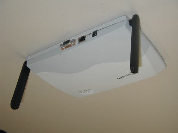
Click to zoom
Application Details
- Equipment Class
- NII - Unlicensed National Information Infrastructure TX
- Date of Grant
- Dec 20, 2001
- Application Purpose
- Original Equipment
- Date of Application
- Dec 19, 2001
- Equipment Note
- Wireless Access Point
- Frequency Range
- 5180.00000000 - 5320.00000000
- Company
- Actiontec Electronics Inc
- Country
- United States
Documents & Files
Document Text
Text extracted from the exhibit documents filed with the FCC. Open a document above to read the original.
Users Manual
Actiontec Electronics, Inc. 802AA User Guide PRELIMINARY Actiontec Electronics, Inc. COMPANY CONFIDENTIAL Contents Preface...............................................................vii About this Document..................................................................................vii Audience...................................................................................................viii Additional Resources.................................................................................viii Regulatory Compliance Information............................................................ix Radio Frequency Interference Requirements..........................................ix FCC Warning.........................................................................................ix RF Exposure Requirements.....................................................................x 1. Introduction..................................................................1-1 Package Contents.......................................................................................1-1 System Requirements.................................................................................1-2 2. Access Point Physical Description...............................1-1 Top Panel...................................................................................................1-1 Rear Panel..................................................................................................1-3 1. AP Web Server..........................................................A-2-2 Accessing the AP Web Server.................................................................A-2-2 Configuration Windows.........................................................................A-2-4 Working With Configuration Windows...........................................A-2-4 General Configuration Window.............................................................A-2-5 PRELIMINARY Actiontec Electronics, Inc. COMPANY CONFIDENTIAL General Advanced Configuration Window............................................A-2-8 Shared Key Configuration......................................................................A-2-8 Per Station Privacy Configuration Window..........................................A-2-10 Script Configuration Window..............................................................A-2-12 Firmware Update Configuration Windows..........................................A-2-14 Statistics Windows...............................................................................A-2-15 AP Statistics...................................................................................A-2-16 Station Statistics.............................................................................A-2-18 PRELIMINARY Actiontec Electronics, Inc. COMPANY CONFIDENTIAL PRELIMINARY Actiontec Electronics, Inc. COMPANY CONFIDENTIAL Preface The intent of this document is to familiarize you with the Actiontec Access Point (AP) Reference Design, its physical characteristics, setup, configuration, and usage. AP hardware developers should refer to the AP Reference Design Functional Specification, AP Hardware Design Guide, AP Reference Design Board Layouts, AP Reference Design Schematics, and AP Reference Design Bill of Materials. AP software developers should refer to the AP Programmer’s Guide. Both the AR5110 Data Sheet and the AR5210 Data Sheet will provide valuable AR5000 chipset reference for both hardware and software developers. After reading this user’s guide, you should be able to install, configure, control, and maintain the Actiontec AP Reference Design provided as part of an Actiontec Evaluation or Developer’s Kit. a. About this Document This document consists of the following chapters and appendixes: Chapter 1 Introduction—Describes the Access Point package contents and system requirements. Chapter Error! Reference source not found. 2. Access Point Physical Description—Provides a physical description of the Access Point. Chapter 2 AP Network Attachment and Configuration— Describes the Access Point network connections and initial software configuration. Appendix A AP Web Server—Describes the use of the web server to configure the Access Point. PRELIMINARY Actiontec Electronics, Inc. COMPANY CONFIDENTIAL b. Audience The intended audience for this user’s guide is evaluators and developers of AP products. The reader is assumed to have conceptual and practical knowledge about AP concepts, features, and functions. This guide relies on the reader’s familiarity with APs in general, while discussing the specific characteristics of the Actiontec AP Reference Design. c. Additional Resources Actiontec Reference Design hardware, software, and documentation contain proprietary information of Actiontec Electronics, Inc., and are provided under a license agreement containing restrictions on use and disclosure, and are also protected by copyright law. Reverse engineering of this hardware, software, or documentation is prohibited. If you are working with an Actiontec Developers Kit, the following resources should be referenced regarding topics that are not addressed in this document: 1. AR5110 Radio-on-a-Chip for 5-GHz Wireless LANs data sheet 2. AR5210 MAC/Baseband Processor for IEEE 802.11a 5-GHz Wireless LAN data sheet 3. AP Reference Design Functional Specification 4. AP Hardware Design Guide 5. AP Reference Design Bill of Materials 6. AP Reference Design Board Layouts 7. AP Reference Design Schematics 8. CLI Quick Reference 9. AP Programmer’s Guide 10. STA User’s Guide PRELIMINARY Actiontec Electronics, Inc. COMPANY CONFIDENTIAL If you are using an Actiontec Evaluation Kit, you may receive a subset of these documents. d. Regulatory Compliance Information This section contains Regulatory Compliance Information for the AP. i. Radio Frequency Interference Requirements This device is restricted to indoor use due to its operation in the 5.15 to 5.25 GHz frequency range. FCC regulations require…
Text truncated - open the document above for the full version.
Cover Letter(s)
American Telecommunications Certification Body Inc. 6731 Whittier Ave, McLean, VA 22101 December 20, 2001 RE: Actiontec Electronics FCC ID: LNQ802AA I have a few comments on this Application. Please note that is usually our policy to not even begin an Application unless all Exhibits have been uploaded. 1.) Please provide a Test Report. 2.) Please provide Test Setup Photos. 3.) FYI: In the future, please take more care with the photographs. They are of marginal quality and have excessive glare from the photo flash. 4.) Block Diagram does not conform with the requirements of 2.1033(b)(5). 5.) Please recheck Equipment Specifications on the Form 731. Frequencies listed as 5180- 5320MHZ, and 5210 to 5290. There is an overlap of over 100MHz. Please correct. 6.) RF Exposure report indicates maximum conducted output power across all channels is 15.7dBm. However different values are used in Normal Mode and Turbo Mode calculations. Please correct. Make sure they agree with Test Report. Thank you, William H. Graff President and Examining Engineer mailto: [email protected] The items indicated above must be submitted before processing can continue on the above referenced application. Failure to provide the requested information may result in application termination. Correspondence should be considered part of the permanent submission and may be viewed from the Internet after a Grant of Equipment Authorization is issued. Please do not respond to this correspondence using the email reply button. In order for your response to be processed expeditiously, you must submit your documents through the AmericanTCB.com website. Also, please note that partial responses increase processing time and should not be submitted. Any questions about the content of this correspondence should be directed to the sender.
ID Label/Location Info
Actiontec 802AA FCC ID: LNQ802AAThis device complies with Part 15 of the FCC Rulesand RSS-210. Operation is subject to the following two conditions:(1)This device may not cause harmful interference(2) This device must accept any interference received, including interference that may cause undesired operation. 802AALabel size: 68 mm (W) x 38 mm (H)
Internal Photos
Enclosure – Top and Bottom Assembly View showing how antennas are connected to the circuit board Top View of Board – Shield in Place Top View of Board – Shield Removed Top View of Board – Shield Removed Bottom View of Board
Operational Description
802.11A WIRELESS ACCESS POINT (AP) FUNCTIONAL SPECIFICATION Serial # 802AA Revision 0.1 11/9/2001 Specifications of 802.11AA Access Point 2 Notice The information in this document has been carefully reviewed and is believed to be accurate. Nonetheless, this document is subject to change without notice and Actiontec Electronics, Inc. (Actiontec) assume no responsibility for any inaccuracies that may be contained in this document, and make no commitment to update or to keep current the contained information, or to notify a person or organization of any updates. Actiontec reserve the right to make change, at any time in order to improve reliability, function, or design and to attempt to supply the best product possible ActionTec doe not represent that products described herein are free from patent infringement or from any other third party right. No part of this document may be reproduce, adapted, or transmitted in any form or by any means, electronic or mechanical, for any purpose except as expressly set forth in written agreement signed by Actiontec. Actiontec or its affiliate may have patents or pending patent applications, trademarks, copyrights, maskwork rights, or other intellectual property rights that apply to the ideas, material, and information expressed herein. No license to such rights is provided except expressly set forth in written agreement signed by ActionTec. ACTIONTEC MAKES NO WARRANTIES OF ANY KIND WITH REGARD TO THE CONTENT OF THIS DOCUMENT. IN NO EVENT SHALL ACTIONTEC BE LIABLE FOR DIRECT, INDIRECT, SPECIAL, INCIDENTAL, SPECULATORY, OR CONSEQUENTIAL DAMAGES ARISING FROM THE USE OR INABILITY TO USE THIS PRODUCT OR DOCUMENTATION, EVEN IF ADVISED OF THE POSSIBLITY OF SUCH DAMAGES. IN PARTICULAR, ACTIONTEC SHALL NOT HAVE LIABILITY FOR ANY HARDWARE, SOFTWARE, OR DATA TRANSMITTED OR OTHERWISE USED WITH THE PRODUCT, INCLUDING THE COSTS OF REPAIRING, REPLACING, INTEGRATING, INSTALLING, OR RECOVERING SUCH HARDWARE, SOFTWARE, OR DATA. ACTIONTEC SPECIFICALLY DISCLAIMS THE IMPLIED WARRANTIES OF MERCHANTIBILITY AND FITNESS FOR A PARTICULAR PURPOSE AS THEY MIGHT OTHERWISE APPLY TO THIS DOCUMENT AND TO THE IDEAS, MATERIAL, AND INFORMATION EXPRESSED HEREIN. Specifications of 802.11AA Access Point 3 Preface This document describes functional details for an IEEE 802.11 wireless LAN access point (AP) reference design. About this Document The document consists of the following chapters: Part 1 Architecture---Describes the system architecture reference design for developing an IEEE 802.11 compatible AP. Part 2 Software---Describe the operating system use for the AP reference design. Part 3 Performance---Provides detailed performance specifications for the AP reference deign. Part 4 Electrical Characteristics---Provides electrical specifications for the AP reference deign. Part 5 Physical Characteristics---Provide s physical characteristics and environmental requirements for the AP reference design. Part 6 Regulatory Compliance---Describes the U.S., Canadian, and Japanese regulatory compliance requirements for the AP reference design. Specifications of 802.11AA Access Point 4 Architecture Figure 1 is a block diagram of the overall access point (AP) reference design. There are three distinct subsystems within the reference deign: 1. MPC8245 processor subsystem 2. 802.11 wireless LAN subsystem 3. 10/100 Mbps Ethernet LAN subsystem Each of thee blocks is describe d in the following sections. 802.11 Wireless AP Block Diagram RS232 Driver Motorola MPC8245 Buffer WLAN 802.11a 10/100 Ethernet Flash Memory 4,8 or 16M SDRAM 16 or 32M JTAG PCI Bus Power Supply Reset Specifications of 802.11AA Access Point 5 MPC8245 Processor Subsystem The processor subsystem include the Motorola MPC8245 integrated processor, which combine powerful power PC 603e core with peripheral blocks that provide functionality common to most embedded applications. This subsystem of the overall access point design include: • MPC8245 integrated processor • Flash memory: The 4, 8 or 16 MB of Flash memory contains the real-time operating system code board support software for the overall AP and power up parameters for the processor, as well as wireless and Ethernet LAN subsystems • SDRAM: The16 or 32 MB of SDRAM provide memory for buffering wireless and Ethernet LAN packets, and space for copying operating system software from the on board Flash device to get faster execution from the SDRAM • PCI bus host functions for embedded peripheral interfacing • RS232 serial interface is provide for configuring the access point from terminal device • JTAG interface for test and debug • Functions that are common to other sections of the overall access point reference design such as power supply and reset circuit Figure 2. MPC8245 Processor Subsystem Block Diagram RS232 Flash Memory 4,8 or 16M CSDRAM 16 or 32 M MPC8245 PCI Bus Power Supply Reset JTAG Specifications of 802.11AA Access Point 6 Processor The Motorola MPC8245 is an integrated processor that combines the Power PC 603e core with peripheral logic block. The peripheral logic block implements functionality that is common to large number of embedded applications. TheMPC8245's integrated peripheral logic block provide the following functionality: • A PCI bridge with an integrated bus arbitrator that allows seamless attachment of predesigned PCI functional blocks to the processor. This interface allows the connection of up to five PCI devices through a set of dedicated request, grant, and interrupt line. • An integrated high performance memory controller that supports various types of DRAMs and ROMs. • A DMA controller. • An integrate SDRAM clock generation capability. • An interrupt controller. • An I2O message controller. • An I2C controller. The Power PC 603e core is full-featured high performance processor with the following functionality: • floating point support • memory management • 16 Kbyte instruction cache • 16 Kbyte data cache • power management features TheMPC8245 contains an i…
Text truncated - open the document above for the full version.
RF Exposure Info
MPE Calculations FCC part 1.1310, Table 1 limits the power density for uncontrolled exposure to 1mW/ cm 2 for systems operating in the UNII bands. The distance, d(cm) from the antenna at which the power density, P d (mW/cm 2 ) is below this limit is calculated from the maximum EIRP, P t (mW) using the equation: P d =P t /(4πd 2 ) Re-arranging for the distance at which the power density is 1mW/cm2 gives: d=√(P t /(4π)) Thedeviceundertestisdesignedtouseanintegralantenna,whichisconfiguredto giveanOmni-Directionalpattern.Thegainstatedfortheomniconfigurationis4dBi. The maximum EIRP for Normal Mode is, therefore, 17 dBm + 4 dBi = 21 dBm (125mW): d=√(125 / (4 π)) =3.15 cm The maximum EIRP for Turbo Mode is, therefore, 16.2 dBm + 4 dBi = 20.2 dBm (104mW): d=√(104 / (4 π)) =2.88 cm The distance from the antenna that the power density is 1mW/ cm 2 is, therefore, 3.15 cm. The users guide instructs the user to install the device such that it has a separation of at least 20cm from persons (see text below) to comply with the FCC’s requirements. This separation of 20cm more than meets the FCC’s and Industry Canada RF exposure requirements. Mode EIRP Calculated (cm) Normal 21 dBm (125mW)3.15 Turbo 20.2 dBm (104mW) 2.88 RF Exposure Requirements To ensure compliance with FCC RF exposure requirements, the antenna used for this device must be installed to provide a separation distance of at least 20 cm from all persons and must not be co- located or operating in conjunction with any other antenna or radio transmitter. Installers and end- users must follow the installation instructions provided in this user guide.
Test Report
File: R45591 Page 1 of 20 Electromagnetic Emissions Test Report and Application for Grant of Equipment Authorization pursuant to FCC Part 15, Subpart E (UNII Devices) and Industry Canada RSS 210 Issue 4 (LELAN Devices) on the ActionTec Electronics, Inc. Model: 802AA FCC ID: LNQ802AA GRANTEE: ActionTec Electronics, Inc. 1269 Innsbruck Drive Sunnyvale, CA 94089 TEST SITE: Elliott Laboratories, Inc. 684 W. Maude Avenue Sunnyvale, CA 94086 REPORT DATE: December 4, 2001 FINAL TEST DATE: November 29, 2001 AUTHORIZED SIGNATORY: ______________________________ Mark Briggs Director of Engineering This report shall not be reproduced, except in its entirety, without the written approval of Elliott Laboratories, Inc. Elliott Laboratories, Inc. -- EMC Department Test Report Report Date: December 4, 2001 File: R 45591 Page 2 of 20 pages DECLARATIONS OF COMPLIANCE Equipment Name and Model: 802AA Manufacturer: ActionTec Electronics, Inc. 1269 Innsbruck Drive Sunnyvale, CA 94089 Tested to applicable standards: RSS-210, Issue 4, December 2000 (Low Power License-Exempt Radiocommunication Devices) FCC Part 15 Subpart E (UNII Devices) Measurement Facility Description Filed With Department of Industry: Departmental Acknowledgement Number: IC2845 SV1 Dated July 30, 2001 Departmental Acknowledgement Number: IC2845 SV4 Dated July 19, 2001 I declare that the testing was performed or supervised by me; that the test measurements were made in accordance with the above mentioned departmental standards (through the use of ANSI C63.4 as detailed in section 5.3 of RSS-210, Issue 4); and that the equipment performed in accordance with the data submitted in this report. Signature ______________________________ Name Mark Briggs Title Director of Engineering Company Elliott Laboratories Inc. Address 684 W. Maude Ave Sunnyvale, CA 94086 USA Date: December 4, 2001 Maintenance of compliance with the above standards is the responsibility of the manufacturer. Any modification of the product, which may result in increased emissions should be checked to ensure compliance has been maintained (i.e., printed circuit board layout changes, different line filter, different power supply, harnessing or I/O cable changes, etc.). Elliott Laboratories, Inc. -- EMC Department Test Report Report Date: December 4, 2001 File: R 45591 Page 3 of 20 pages TABLE OF CONTENTS COVER PAGE...................................................................................................................................................................................1 DECLARATIONS OF COMPLIANCE......................................................................................................................................2 TABLE OF CONTENTS..............................................................................................................................................................3 SCOPE............................................................................................................................................................................................5 OBJECTIVE...................................................................................................................................................................................5 SUMMARY OF RESULTS...........................................................................................................................................................6 MEASUREMENT UNCERTAINTIES....................................................................................................................................8 EQUIPMENT UNDER TEST (EUT) DETAILS..........................................................................................................................9 GENERAL...................................................................................................................................................................................9 ENCLOSURE..............................................................................................................................................................................9 MODIFICATIONS.....................................................................................................................................................................9 SUPPORT EQUIPMENT...........................................................................................................................................................9 INTERFACE PORTS...............................................................................................................................................................10 TEST SOFTWARE..................................................................................................................................................................10 ANTENNA REQUIREMENTS...............................................................................................................................................10 TEST SITE....................................................................................................................................................................................11 GENERAL INFORMATION...................................................................................................................................................11 CONDUCTED EMISSIONS CONSIDERATIONS...............................................................................................................11 RADIATED EMISSIONS CONSIDERATIONS..................................................................................................................11 MEASUREMENT INSTRUMENTATION................................................................................................................................12 RECEIVER SYSTEM................................................................................................................................................................…
Text truncated - open the document above for the full version.
Test Setup Photos
Elliott Laboratories, Inc. -- EMC Department Test Report Report Date: December 4, 2001 File: R45591 Appendix Page 3 of 14 EXHIBIT 3: Test Configuration Photographs 3 Pages Elliott Laboratories, Inc. -- EMC Department Test Report Report Date: December 4, 2001 File: R45591 Appendix Page 4 of 14 Radiated Emissions Above 1 GHz Elliott Laboratories, Inc. -- EMC Department Test Report Report Date: December 4, 2001 File: R45591 Appendix Page 5 of 14 Radiated Emissions Below 1 GHz Elliott Laboratories, Inc. -- EMC Department Test Report Report Date: December 4, 2001 File: R45591 Appendix Page 6 of 14 Conducted Emissions
Contact Information
Applicant
Brian Henrichs(President)
Technical Contact
Elliott Laboratories, Inc.Juan Martinez
[email protected]408 245 7800
684 W. Maude Ave. · Sunnyvale, California · United States
Test Firm
Elliott Laboratories LLCDavid Bare
Technical Specifications
| # | Rule Parts | Frequency Range | Power Output |
|---|---|---|---|
| 1 | 15E | 5.18 GHz - 5.32 GHz | 50.00 mW |
Other Applications from Actiontec Electronics Inc

LNQWF672
Dec 26, 2025Wi-Fi 7 Outdoor Mesh AP
Equipment Class
DTS - Digital Transmission System
LNQ-WF670G
Dec 09, 2025Wi-Fi 7 Outdoor Mesh AP
Equipment Class
DTS - Digital Transmission SystemLNQ-WF815-2
Apr 14, 2024Tri-band Wi-Fi 6E Wireless AP
Equipment Class
DTS - Digital Transmission System
LNQ-WF825
Mar 24, 2024Tri-band Wi-Fi 7 Wireless AP
Equipment Class
6ID - 15E 6 GHz Low Power Indoor Access Point
LNQ-WF810G-2
Mar 23, 2024Wi-Fi 6E Mesh Extender
Equipment Class
DTS - Digital Transmission System