LNQ802AIWireless LAN Device
Actiontec Electronics Inc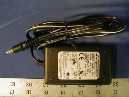
Click to zoom
Application Details
- Equipment Class
- DSS - Part 15 Spread Spectrum Transmitter
- Date of Grant
- Dec 06, 2001
- Application Purpose
- Original Equipment
- Date of Application
- Dec 06, 2001
- Equipment Note
- Wireless LAN Device
- Frequency Range
- 2413.44000000 - 2460.78000000
- Company
- Actiontec Electronics Inc
- Country
- United States
Documents & Files
Document Text
Text extracted from the exhibit documents filed with the FCC. Open a document above to read the original.
Users Manual
1 Table of Contents l. Introduction 2 ll. Contacting Technical Support3 lll. Introduction to Wireless Networks 4 IV. Installing the Actiontec 802.11b Wireless Access Point 7 V. Configuring the Actiontec 802.11b Wireless Access Point 11 VI Troubleshooting 21 VII Frequently Asked Questions 22 VIII Regulatory notes and statements 24 IX Warranty statements 26 Proprietary Notice and Disclaimer Unless otherwise noted, this document and the information herein disclosed are proprietary to Actiontec Electronics, Inc the manufacturer. Any person or entity to whom this document is furnished or who otherwise has possession thereof, by acceptance agrees that it will not be copied or reproduced in whole or in part, nor used in any manner except to meet the pur- poses for which it was delivered. The information in this document is subject to change without notice and should not be con- strued as a commitment by Actiontec the manufacturer. Although Actiontec the manufac- turer will make every effort to inform users of substantive errors, Actiontec the manufactur- er disclaims all liability for any loss or damage resulting from the use of this document or any hardware or software described herein, including without limitation contingent, special or incidental liability. Note:PC is a trademark of IBM Corporation. Windows 98 and 98 SE is a trademark of Microsoft Inc. All other brand or product names and logos used in this manual are trademarks or registered trademarks of their respective holders. Table of Contents ????-????-??? Page 3 Contacting Technical Support 2 Introduction Actiontec Electronics prides itself on making high-quality, durable, high-performance products. If you should need assistance, the Actiontec Technical Support Department is available 6 am to 11pm Mon - Sun (Mountain Time), to provide professional sup- port. Contacting Technical Support Actiontec Electronics, Inc. 760 N. Mary Avenue Sunnyvale, CA 94085 Phone: 1-719-884-8300 E-mail: [email protected] Thank you for purchasing the Actiontec 802.11b Wireless Access Point. This Wireless Access Point is easy to use and easy to setup. If you like the freedom of accessing your network from anywhere within your home or office, then take your networking to the next level with the Actiontec 802.11b Wireless Access Point. You will be able to have full access to your network and share files, printers and even your High-Speed Internet access. Package Contents Make sure the following items came in this package: Actiontec 802.11b Wireless Access Point and power adapter Actiontec 802.11b Wireless Access Point Installation CD-ROM Accessories bag (lugs, screws, etc...) This User’s Manual and Quick Start Installation Guide Warranty Card Minimum System Requirements PC Computer with an Ethernet Adapter configured for TCP/IP. Internet Browser (Microsoft Explorer, Netscape Navigator, etc..). Microsoft Windows 2000/Windows Millennium Edition, Windows 98 Second Edition (SE), XP/Windows NT 4.0 Introduction 5 Introduction to Wireless Networks 4 Introduction to Wireless Networks A wireless network connects computers to each other using radiotechnology which allows you the freedom to move around the area and work anywhere within reach of an Access Point. The Actiontec 802.11b Wireless Access Point can be connected to a wired network. This allows communication between the wired network and computers using Actiontec 802.11b Wireless PC Cards. The technology is an extension to the exist- ing Ethernet networking standard, so you can connect the Actiontec 802.11b Access Point to an existing Ethernet network. Adding Access Points to your network Placement and connection of the Actiontec 802.11b Access Point depends entirely on your specific (network) environment. The Actiontec 802.11b Access Point can be used for the following configurations: Creating a wireless network. Extending an existing wireless network. Connecting to a single computer. Creating a wireless network Your Actiontec 802.11b Access Point can be used to setup a wireless network as shown on figure 1. Follow the steps below to create a wireless network. Introduction to Wireless Networks Figure 1. Creating a Wireless Network Note: Refer to the appropriate user manual for successful installation of your wireless network. 1. Prepare one computer that you will want to connect wirelessly. (Install wireless network card and software). 2. Configure the IP settings for this client computer. 3.Install the Actiontec 802.11b Access Point. 4. Your 802.11b wireless network is now ready. 5. For further functionality and security, the Actiontec 802.11b Access Point can be configured using the Actiontec 802.11b Access Point KickStart software utility and the Web Interface. 6. Install other client computers if this is applicable to your environment. Extending a wired network with one or more Actiontec 802.11b Access Points When the Actiontec 802.11b Access Point is used as an extension to a wired net- work (figure 2), please make sure that the current wired network is completely functional. Note: Refer to the appropriate user manual for successful installation of your wireless network. Follow these steps to extend you wired network: 1. Install the Actiontec 802.11b Access Point and connect it to your wired network. 2. You can now use the wireless network. Figure 2. Extending a Wired Network 7 Installing the Actiontec 802.11b Access Point This equipment is designed with utmost care for the safety of those who install and use it. However, special attention must be paid to the dangers of electric shock and static electricity when working with electronic equipment. All guidelines of this manual and of the computer manufacturer must therefore be followed at all times to ensure the safe use of the equipment. Physical installation of the Actiontec 802.11b Wireless Access Point For best performance, and range, the Actiontec 802..11b Access point needs to be placed in an upright vertical position with the antennae extended u…
Text truncated - open the document above for the full version.
External Photos
EUT – Front View EUT – Rear View EUT – Side View Power Adapter Top View
ID Label/Location Info
Proposed FCC ID Label and FCC DOC Label Proposed FCC ID Location Bottom Side of the EUT
Internal Photos
EUT – Component View EUT – Solder View EUT – Transmitter View
Operational Description
SPECIFICATIONS of 802.11b Access Point: 802AI Version 1 Date: 08/27/01 Specifications of Low Profile PCI 802.11b Card 2 Contents 1. Device Overall Description - Block Diagram - Modulation Methods - Channel Assignment 2. Features - ISL3865 CK - Firmware - Management - Throughput /coverage 3. RF Characteristics 4. Software & OS support 5. Regulation 6. Interoperability 7. Operating Conditions 8. Power requirement and dissipation 9. Mechanic and weight Specifications of Low Profile PCI 802.11b Card 3 1. Device Overall Description The 802AI is designed to provide IEEE 802.11b complianted WLAN Access Point application. It is a long- range, high performance LAN product, which provides Access Point services to a 2,4 GHz RF net-work and bridges to an Ethernet backbone. The design is based on Intersil ISL3865 Access point Controller, which implements the full IEEE802.11b standard date rates up to 11Mbps. Block Diagram The access point product is based on ISL3865CK module, It is an Arm940 core controller with an onboard MAC to Ethernet(10/100 Base T) interface. The ISL3856 directly interfaces with the Intersil HFA386x family of Baseband Processors, offering a complete end-to-end IEEE 802.11b compliant chip set solution for wireless LAN products. Protocol and PHY support are implemented in firmware to allow custom protocol and different PHY transceivers. The ISL3856 is a Harvard architecture cached processor. The separate instruction and data caches in this design are 4K bytes each in size with a four-word line length. A protection unit allows the memory to be segmented and protected in a simple manner. There is no virtual physical address mapping. Write-back cache schemes and write buffers are used to optimize performance and minimize bus traffic thus reducing system power consumption. This Processor Core is implemented using a five-stage pipeline consisting of fetch, decode, execute, memory and write stages. Firmware implements the full IEEE 802.11b Wireless LAN MAC protocol. It supports Infrastructure mode BSS operation under DCF, and operation under the optional Point Coordiantion Function (PCF). All low-level 802.11 functions are handled by firmware. Additional firmware functions specific to access point applications are also available. The ISL3856 is the industry's first Access Point on a chip, which implements both the IEEE 802.11 MAC protocol and the MAC bridging function, which in alternative solutions requires a separate external processor. For network management, an SNMP agent is implemented for access to the MIB. Designing wireless protocol systems using the ISL3856 is made easier with Intersil supplied firmware, software device drivers, and complete documentation. ISL3865CK Intersil,ARM MAC processor. Lu3x31T: Lucent ,10/100 Ethernet transceiver. HFA3863IN: Intersil, Baseband Processor HFA3783IN: Intersil, I/Q Modulator/Demodulator and Synthesizer HFA3683: Intersil, 2.4GHz RF/IF Converter and Synthesizer HFA3983: Intersil, 2.4GHz Power Amp and Detector ICW3183: Intersil, 748MHz Voltage Controlled Oscillator ???? Specifications of Low Profile PCI 802.11b Card 4 3863 BBP 3783 MODEM SYNT VCO CLOCK 3683 RF/IF CONVERTER VCO DIVERSITY SW. 3983POWER AMP LU3x31T Ethernet SRAM FLASH CLOCK 3856 MAC Specifications of Low Profile PCI 802.11b Card 5 Modulation Methods Modulation spec. 1 Mbps DBPSK 802.11 2 Mbps DQPSK 802.11 5.5 Mbps CCK 802.11b 11 Mbps CCK 802.11b Channel Assignment Channel Frequency FCC IC ETSI France Japan 1 2412MHz X X X X 2 2417MHz X X X X 3 2422MHz X X X X 4 2427MHz X X X X 5 2432MHz X X X X 6 2437MHz X X X X 7 2442MHz X X X X 8 2447MHz X X X X 9 2452MHz X X X X 10 2457MHz X X X X X 11 2462MHz X X X X X 12 2467MHz X X X 13 2472MHz X X X 14 2484MHz X Many countries and region are currently revising the channel assignment. Specifications of Low Profile PCI 802.11b Card 6 2. Features ISL3865CK FEATURES: Among the features of the ISL3865CK are the following: • ARM940T core. • Baseband Processor Interface providing a direct transmit and receive serial interfaces to an external baseband processor. • Serial Control Port (SCP), supporting serial communication for control of external devices. • Memory Interfaces supporting SRAM, ROM and SDRAM memories, at 8, 16 or 32 bits. • Real Time Clock. • MII Interface • 3 General Purpose Timers. • Interrupt Controller. • 16 General Purpose I/Os (GPIO). • A UART to enable system debugging, multiplexed onto GPIO lines. • On-chip PLL for clock generation. • Test Interface Controller (TIC) to support manufacturing tests. • JTAG interface for boundary scan and debug port. • Power management capabilities. • IEEE802.11 Standard Data Rates: 1, 2, 5.5 and 11Mbps • Part of the Intersil PRISM Wireless LAN Chip Set • Full Implementation of the MAC Protocol Specified in IEEE Standards 802.11-1999 and 802.11b • Operation at 3.3V Supply • Package 169 pin uBGA Package Targeted for compact gateways Firmware Features The IEEE 802.11b firmware implementation for the 802AI supports: – Standard Firmware features, such as – Distributed Coordination Function CSMA/CA Backoff Procedure NAV Management ACK Procedure Retransmission of unacknowledged frames – RTS/CTS Handshake – Duplicate Detection and Recovery – Beacon Generation – Probe Response – Fragmentation and Reassembly – Authentication Algorithm (Open System, Shared Key) – Short Preamble – – 802.11 Mandatory – WEP40/128 – ASBF – SNMP Agent – Power management – User CAC/ACL (128/1024) – Web server – Roaming: Among APs on the same subnet – DHCP – Operation Modes supported: Access Point – Network Interface: supports 10/100 Mbps network interface. Specifications of Low Profile PCI 802.11b Card 7 – Radio Interface As far as the radio interface is concerned, it supports: Antenna Diversity and Specific Antenna Tx/Rx Management feature For Bridge Management, it supports: – Standard bridging function – Automatic Learning Process – Filtering Database – Forwarding Process – IP Filtering – Aging Function – Static Filtering Entr…
Text truncated - open the document above for the full version.
Test Report
Note: This test report is specially limited to the above client company and the product model only. It may not be duplicated without prior written consent of Bay Area Compliance Laboratory Corporation. This report must not be used by the client to claim product endorsement by NVLAP or any agency of the U.S. Government. FCC 15 SUBPART C EMI MEASUREMENT AND TEST REPORT For Actiontec Electronics, Inc. 760 North Mary Avenue Sunnyvale, CA 94086 FCC ID: LNQ802AI December 5, 2001 This Report Concerns: Original Report Equipment Type: Wireless LAN Device Test Engineer: Jeff Lee Test Date: October 17, 2001 Reviewed By: John Y. Chan – Engineering Manager Prepared By: Bay Area Compliance Laboratory Corporation 230 Commercial Street Sunnyvale, CA 94085 Tel: (408) 732-9162 Fax: (408) 732 9164 Actiontec Electronics, Inc. FCC ID: LNQ802AI Report # R0110171 FCC 15.247 Test Report Page 2 of 24 TABLE OF CONTENTS 1 - GENERAL INFORMATION..................................................................................................................................4 1.1 PRODUCT DESCRIPTION FOR EQUIPMENT UNDER TEST (EUT) ..............................................................................4 1.2 OBJECTIVE.............................................................................................................................................................4 1.3 RELATED SUBMITTAL(S)/GRANT(S).......................................................................................................................4 1.4 TEST METHODOLOGY............................................................................................................................................4 1.5 TEST FACILITY.......................................................................................................................................................4 1.6 TEST EQUIPMENT LIST AND DETAILS.....................................................................................................................5 1.7 HOST SYSTEM CONFIGURATION LIST AND DETAILS..............................................................................................5 1.8 LOCAL SUPPORT EQUIPMENT LIST AND DETAILS...................................................................................................6 1.9 EXTERNAL I/O CABLING LIST AND DETAILS.........................................................................................................6 2 - SYSTEM TEST CONFIGURATION.....................................................................................................................7 2.1 JUSTIFICATION.......................................................................................................................................................7 2.2 EUT EXERCISE SOFTWARE....................................................................................................................................7 2.3 SPECIAL ACCESSORIES...........................................................................................................................................7 2.4 SCHEMATICS / BLOCK DIAGRAM...........................................................................................................................7 2.5 EQUIPMENT MODIFICATIONS.................................................................................................................................7 2.6 CONFIGURATION OF TEST SYSTEM.........................................................................................................................8 2.7 TEST SETUP BLOCK DIAGRAM...............................................................................................................................8 3 - SUMMARY OF TEST RESULTS..........................................................................................................................9 4 - CONDUCTED OUTPUT POWER MEASUREMENT......................................................................................10 4.1 STANDARD APPLICABLE......................................................................................................................................10 4.2 MEASUREMENT PROCEDURE................................................................................................................................10 4.3 MEASUREMENT RESULT......................................................................................................................................10 5 – SPURIOUS EMISSION ........................................................................................................................................12 5.1 STANDARD APPLICABLE.......................................................................................................................................12 5.2 MEASUREMENT PROCEDURE................................................................................................................................12 5.3 MEASUREMENT DATA..........................................................................................................................................12 6 – POWER DENSITY ...............................................................................................................................................13 6.1 STANDARD APPLICABLE......................................................................................................................................13 6.2 MEASUREMENT PROCEDURE................................................................................................................................13 6.3 TEST RESULTS.....................................................................................................................................................13 7 – 6 DB BANDWIDTH ..............................................................................................................................................14 7.1 STANDARD APPLICABLE...............................................................…
Text truncated - open the document above for the full version.
Test Setup Photos
Conducted Emission – Front View Conducted Emission – Rear View Radiated Emission – Front View Radiated Emission – Rear View
Contact Information
Applicant
Brian Henrichs(President)
Test Firm
Bay Area Compliance LaboratoryJohn Chan
Technical Specifications
| # | Rule Parts | Frequency Range | Power Output |
|---|---|---|---|
| 1 | 15C | 2.41 GHz - 2.46 GHz | 36.00 mW |
Other Applications from Actiontec Electronics Inc

LNQWF672
Dec 26, 2025Wi-Fi 7 Outdoor Mesh AP
Equipment Class
DTS - Digital Transmission System
LNQ-WF670G
Dec 09, 2025Wi-Fi 7 Outdoor Mesh AP
Equipment Class
DTS - Digital Transmission SystemLNQ-WF815-2
Apr 14, 2024Tri-band Wi-Fi 6E Wireless AP
Equipment Class
DTS - Digital Transmission System
LNQ-WF825
Mar 24, 2024Tri-band Wi-Fi 7 Wireless AP
Equipment Class
6ID - 15E 6 GHz Low Power Indoor Access Point
LNQ-WF810G-2
Mar 23, 2024Wi-Fi 6E Mesh Extender
Equipment Class
DTS - Digital Transmission System