LNQ802CA802.11a Wireless LAN PC Card
Actiontec Electronics Inc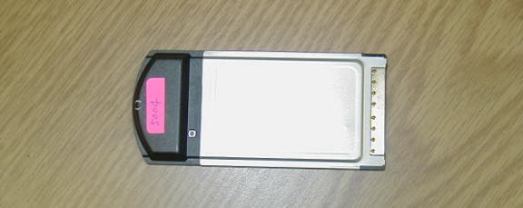
Click to zoom
Application Details
- Equipment Class
- NII - Unlicensed National Information Infrastructure TX
- Date of Grant
- Nov 18, 2001
- Application Purpose
- Original Equipment
- Date of Application
- Nov 18, 2001
- Equipment Note
- 802.11a Wireless LAN PC Card
- Frequency Range
- 5250.00000000 - 5350.00000000
- Company
- Actiontec Electronics Inc
- Country
- United States
Documents & Files
Document Text
Text extracted from the exhibit documents filed with the FCC. Open a document above to read the original.
Users Manual
1 Table of Contents l.Introduction2 ll.Contacting Technical Support3 lll.Connecting the Actiontec 802.11a Wireless PCCard4 lV.Installing the Actiontec 802.11a Wireless PCCard5 Configuring Windows ME5 Configuring theActiontec 802.11a Wireless PC Card7 Setting AdHoc Mode8 Setting infrastructure Mode10 TCP/IPConfiguration12 Un-installing the Actiontec 802.11a Wireless PCCard14 Configuring Windows 200016 Configuring theActiontec 802.11a Wireless PC Card19 Setting AdHoc Mode20 Setting infrastructure Mode21 TCP/IPConfiguration23 Un-installing the Actiontec 802.11a Wireless PCCard25 VConfiguring File and Print Sharing28 Windows ME28 Windows 200033 VIActiontec 802.11a Wireless PCCard Operating Modes35 VIITroubleshooting36 VIIIFrequently Asked Questions38 Proprietary Notice and Disclaimer Unless otherwise noted, this document and the information herein disclosed are proprietary to Actiontec Electronics, Inc the manufacturer. Any person or enti- ty to whom this document is furnished or who otherwise has possession thereof, by acceptance agrees that it will not be copied or reproduced in whole or in part, nor used in any manner except to meet the purposes for which it was delivered. The information in this document is subject to change without notice and should not be construed as a commitment by Actiontec the manufacturer. Although Actiontec the manufacturer will make every effort to inform users of substantive errors, Actiontec the manufacturer disclaims all liability for any loss or dam- age resulting from the use of this document or any hardware or software described herein, including without limitation contingent, special or incidental lia- bility. Note:PC is a trademark of IBM Corporation. Windows 98 and 98 SE is a trademark of Microsoft Inc. All other brand or product names and logos used in this manual are trademarks or registered trademarks of their respective holders. Table of Contents ????-????-??? Page 3 Contacting Technical Support 2 Introduction Actiontec Electronics prides itself on making high-quality, durable, high-performance products. If you should need assistance, the Actiontec Technical Support Department is available 6 am to 11pm Mon - Sun (Mountain Time), to provide professional sup- port. Contacting Technical Support Actiontec Electronics, Inc. 760 N. Mary Avenue Sunnyvale, CA 94086 Phone: 1-719-884-8300 E-mail: [email protected] Thank you for purchasing the Actiontec 802.11a Wireless PC card. This Wireless PC Card is easy to use and easy to setup. If you are tired of all those messy wires needed to con- nect a laptop to your Home network, then take your networking to the next level with the Actiontec 802.11a Wireless PC Card. You will be able to have full access to your network and share files, printers and even your High-Speed Internet access wirelessly from any- where within your home. Package Contents Make sure the following items came in this package: Actiontec 802.11a Wireless PC Card Actiontec 802.11a Wireless PC Card Installation CD-ROM This User’s Manual and Quick Start Installation Guide Warranty Card Minimum System Requirements PC Laptop computer with a 32-bit CardBus slot (PCMCIA Slot) or PC Computer with a 32-bit CardBus slot (PCMCIA) reader. 128 MB RAM or greater 733 MHz processor or higher Microsoft Windows 2000/Windows Millennium Edition, Windows 98 Second Edition (SE), XP/Windows NT 4.0 (with Service Pack 6) Introduction 5 Installing the Actiontec 802.11a NetworkingPCCard 4 Connecting the Actiontec 802.11a Wireless PCCard 1.Your computer can be on or off, it will not affect the installation process.Locate an avail- able Type II or Type III PCMCIA slot on your laptop. If you are not sure where this may be, please consult your laptop’s User Manual. 2.Insert the Actiontec 802.11b Wireless PCCard into the appropriate PCMCIA slot. Your hardware is now installed. Connecting the Actiontec 802.11a Wireless PCCard Configuring Windows ME (Millennium Edition) 1.After you have installed the PC Card your computer will display the following dialog box. Choose “Specify the location of the driver (Advanced)” and click Nextto continue. Installing the Actiontec 802.11a Wireless PC Card 2.Please insert the Actiontec 802.11a Wireless PC Card Installation CD into your CD-ROM drive. In the next screen, select the option Search for the best driv- er for your device (Recommended)and select “Removable Media (Floppy, CD-ROM..) then click the Nextbutton. This device complies with Part 15 of FCC Rules., as well as ICES 003 B / NMB 003 B. Operation is subject to the following two conditions: (1) this device may not cause harmful interference, and(2) this device must accept any interference received, including interference that may cause undesirable operation. Modifications not expressly authorized by Actiontec Electronics may invalidate the user's right to operate this equipment. WARNING!! While this device is in operation, a separation distance of at least 20 centimeters must be maintained between the radiating antenna and the body of all persons exposed to the transmitter in order to meet the FCC RF exposure guidelines. 7 Installing theActiontec 802.11a Wireless PCCard 6 Installing theActiontec 802.11a Wireless PCCard 3.When the Actiontec 802.11a Wireless PCCard driver has been found, click Nextto con- tinue. 4.Click Finishto continue, and restart the system to complete driver installation. Note:Once the system is restarted, theActiontec 802.11a Wireless PC Card will display two flashing green lights. . Configuring the Actiontec 802.11a Wireless PC Card. Configuration of the Actiontec 802.11a Wireless PC Card can be done through the Actiontec 802.11a configuration utility found in the Windows Control Panel. To launch the configuration utility, go to the Control Panel and double-click on the Actiontec 802.11a NIC configuration. The configuration utility allows addition, modification, and deletion of configuration profiles. Select one of the existing configuration profiles under th…
Text truncated - open the document above for the full version.
Cover Letter(s)
American Telecommunications Certification Body Inc. 6731 Whittier Ave, McLean, VA 22101 November 13, 2001 RE: Actiontec Electronics, Inc. FCC ID: LNQ802CA After a review of the submitted information, I have a few comments on the above referenced Application. 1) Please confirm (Y/N) if the fundamental envelope changes over different bit rates. 2) Peak power measurements made with a spectrum analyzer (pg. 10 and 31 of 54) state that the measurements were made with RBW= 1 MHz, VBW = 30 kHz and using the max hold function. Please clarify if the power was summed across the fundamental envelope. 3) The antenna gain of the integral antenna was not consistent throughout the report. Page 17 of 54 states 1.45 dBi, while page 38 of 54 and the RF exposure information states 1.2 dBi. Please comment on this inconsistency. 4) The output power on the summary page (page 6 of 19) for 5.15 to 5.25 Band does not match test report for Turbo Mode. Please correct this error. 5) The device is listed as Class B regarding digital device emissions, however page 52 of 54 states that measurements from 30 - 1000 MHz were made at 10 meters. Please comment. Timothy R. Johnson Examining Engineer mailto: [email protected] The items indicated above must be submitted before processing can continue on the above referenced application. Failure to provide the requested information may result in application termination. Correspondence should be considered part of the permanent submission and may be viewed from the Internet after a Grant of Equipment Authorization is issued. Please do not respond to this correspondence using the email reply button. In order for your response to be processed expeditiously, you must submit your documents through the AmericanTCB.com website. Also, please note that partial responses increase processing time and should not be submitted. Any questions about the content of this correspondence should be directed to the sender.
Cover Letter(s)
RE: Actiontec Electronics, Inc. FCC ID: LNQ802CA 1) Please confirm (Y/N) if the fundamental envelope changes over different bit rates. Response: No 2) Peak power measurements made with a spectrum analyzer (pg. 10 and 31 of 54) state that the measurements were made with RBW= 1 MHz, VBW = 30 kHz and using the max hold function. Please clarify if the power was summed across the fundamental envelope. Response: Yes, the HP8563E has a channel power function, which measures the total power across the fundamental evelope by using the 26-dB bandwidth. 3) The antenna gain of the integral antenna was not consistent throughout the report. Page 17 of 54 states 1.45 dBi, while page 38 of 54 and the RF exposure information states 1.2 dBi. Please comment on this inconsistency. Response: The correct gain is 1.2 dBi. The report has been revised with the correct gain. 4) The output power on the summary page (page 6 of 19) for 5.15 to 5.25 Band does not match test report for Turbo Mode. Please correct this error. Response: Has been corrected as requested. Report has been revised 5) The device is listed as Class B regarding digital device emissions, however page 52 of 54 states that measurements from 30 - 1000 MHz were made at 10 meters. Please comment. Response: Has been corrected as requested. Report has been revised
External Photos
External Photographs Top Side Bottom Side
ID Label/Location Info
Label and Label Location The Label and its location are shown below. Material and attachment details are on the following page.
Internal Photos
Internal Photographs Internal Assembly View Top View of Board with shield Top View of Board without shield Bottom View of Board
Operational Description
Page 1 of 4 Basic Operation Principle of 802CA WLAN Cards ActionTec Electronics, Inc. 11/2001 This description is based upon the “Block Diagram of 802CA WLAN Cards”. Actiontec 802CA is an IEEE 802.11a 5GHz Wireless Local Area Networking (WLAN) card, which consists of AR5210, AR5110 chipset of Atheros Communications. AR5210 --- MAC/Baseband Processor AR5210 integrates the media access control (MAC), baseband processing functions, CardBus interface, and A/D, D/A converters. It also contains a PLL (phase lock loop), which provides different core operating frequencies when running on 802.11a normal mode or turbo mode (40MHz for normal mode, 80MHz for turbo mode). MAC functionality is partitioned between the host and the baseband processor (PHY). MAC data service is provided by protocol control unit (PCU, part of MAC), while the host software, with the aid of DMA engine (also part of MAC), controls transmit and receive queue processing, and antenna selection protocol. The digital physical layer is a half duplex, OFDM baseband processor compliant with IEEE 802.11a. All data rates defined by the 802.11a standard are supported including modulation schemes BPSK for 6, 9Mb/s, QPSK for 12, 18Mb/s, 16-QAM for 24, 36Mb/s and 64-QAM for 48, 54Mb/s. In addition, enhanced turbo mode provides data rate up to 72Mb/s, which is even higher than the rates specified by IEEE 802.11a. The I/Q signals on TX side will output through DAC, and the I/Q signals on RX side will input to ADC. EEPROM This EEPROM is 256x16 bits in size and is used for storing configuration information for the CardBus. The AR5210 provides a serial interface for accessing the external EEPROM. F --- Anti aliasing filter There are two sets of reconstruction filters, one for TX and another for RX, partitioned between AR5210 and AR5110, which have 20MHz band width. They are used for shaping the channel spectrum, removing spectral images and out of band noise. Page 2 of 4 AR5110 --- TX/RX with Modulation/Demodulation The AR5110 is a fully integrated tranceiver with a built in preamplifier, synthesizer, mixers and modulation/demodulation functions. The transmitter combines baseband in- phase (I) and quadrature (Q) signals, up-converts them to the desired channels (5.15~5.35GHz), and drivers the RF signal off-chip through the integrated pre-amp. The receiver down converts the RF signal to IF (intermediate frequency), then through dual conversion IF mixer demodulates I and Q. The frequency synthesizer operates over the entire band with 10MHz steps to match the channel frequency defined by IEEE 802.11a, as well as supporting the turbo mode. The TX, RX and frequency synthesizer are controlled using AR5210 through a serial programming bus and on-chip control registers. LPF --- Low pass filter This is the loop filter of the on chip synthesizer. It’s band width is 15KHz. CH F --- Channel filters The channel select filters are third order elliptical filters designed to pass 8MHz when running in 802.11a normal mode, or 16MHz for turbo mode. The band width control bit is set through the on-chip digital control logic. These filters are to attenuate the out of band interference signals. AR5110 will switch automatically to the correct filter based on the selected normal or turbo mode. 32MHz Crystal The 32MHz crystal provides core clock for AR5110. It’s attached to AR5110, which has an on-chip oscillator. The output of the oscillator connects to its internal frequency synthesizer, and also routs the output of the oscillator to an interface pin for use by AR5210. The absolute error of crystal frequency has to be held within ±20ppm across the operating temperature range. During the final tests, ATE (automatic test equipment) software is going to check the frequency error of channel carriers. If it’s over ±20ppm, a “Fail” warning will show up on PC screen. The reason of doing this is that there is a 30MHz guard band between the band edges and the lowest channel frequency of 5.18GHz and the highest channel frequency of 5.32GHz. With ±20ppm tolerance, the max frequency deviation will be less than 110KHz, so that the emissions are going to be completely contained within UNII 1 and 2 bands under the normal operation specified by IEEE802.11a. M/B --- Matching Baluns There are two Balun transformers in the whole system, one for TX and another for RX. The TX Balun is used to convert a differential balanced signal into an unbalanced signal for transmission, and also provides matching between AR5110 and high pass filter. The RX Balun converts unbalanced signals from the antenna into differential balanced signals, and also provides matching between LNA and AR5110. Page 3 of 4 HPF --- High pass filter Adding HPF between AR5110 and Booster is to reject the LO leakage. LNA --- Low noise amplifier The LNA provides an additional 12dB gain and reduces overall noise figure by approximately 5dB, so that the system receiving sensitivity can be guaranteed within 802.11a standard. OPB --- Output Booster OPB boosts the output power of AR5110 up to 18~20dBm. It’s a single stage amplifier. BPF --- Band pass filter The BPF is designed to pass frequencies between 5.15 and 5.35 GHz and is used to protect the receiver from the unwanted frequencies. TX/RX ANT Switch --- Transmitter, receiver antenna switch This switch enables the connection of either the LNA or the PA to one of two diversity antennae. LPF --- Low pass filters Two LPFs are inserted between two antennae and TX/RX switch. They are designated for getting rid of any harmonics of channel frequencies. Compliance with FCC requirement 15.407 (c): The TX path of the digital signal processor board will only output a baseband signal to the baseband board when DS3 data is present at it’s input. The baseband board has a TX baseband detector circuit that sends a signal to the micro processor to indicate if a TX baseband signal is present. If a TX baseband signal is not present the micro processor sends a control signal to the RF board tha…
Text truncated - open the document above for the full version.
Test Report
File: R45194 Page 1 of 19 Electromagnetic Emissions Test Report and Application for Grant of Equipment Authorization pursuant to FCC Part 15, Subpart E (UNII Devices) and Industry Canada RSS 210 Issue 4 (LELAN Devices) on the ActionTec Electronics, Inc. Model: 802CA FCC ID: LNQ802CA GRANTEE: ActionTec Electronics, Inc. 1269 Innsbruck Drive Sunnyvale, CA 94089 TEST SITE: Elliott Laboratories, Inc. 684 W. Maude Avenue Sunnyvale, CA 94086 REPORT DATE: October 29, 2001 FINAL TEST DATE: October 12, October 15 and October 16, 2001 AUTHORIZED SIGNATORY: ______________________________ Mark Briggs Director of Engineering This report shall not be reproduced, except in its entirety, without the written approval of Elliott Laboratories, Inc. Elliott Laboratories, Inc. -- EMC Department Test Report Report Date: October 29, 2001 File: R 45194 Page 2 of 19 Pages DECLARATIONS OF COMPLIANCE Equipment Name and Model: 802CA Manufacturer: ActionTec Electronics, Inc. 1269 Innsbruck Drive Sunnyvale, CA 94089 Tested to applicable standards: RSS-210, Issue 4, December 2000 (Low Power License-Exempt Radiocommunication Devices) FCC Part 15 Subpart E (UNII Devices) Measurement Facility Description Filed With Department of Industry: Departmental Acknowledgement Number: IC2845 SV3 Dated July 30, 2001 Departmental Acknowledgement Number: IC2845 SV4 Dated July 19, 2001 I declare that the testing was performed or supervised by me; that the test measurements were made in accordance with the above mentioned departmental standards (through the use of ANSI C63.4 as detailed in section 5.3 of RSS-210, Issue 4); and that the equipment performed in accordance with the data submitted in this report. Signature ______________________________ Name Mark Briggs Title Director of Engineering Company Elliott Laboratories Inc. Address 684 W. Maude Ave Sunnyvale, CA 94086 USA Date: October 29, 2001 Maintenance of compliance with the above standards is the responsibility of the manufacturer. Any modification of the product which may result in increased emissions should be checked to ensure compliance has been maintained (i.e., printed circuit board layout changes, different line filter, different power supply, harnessing or I/O cable changes, etc.). Elliott Laboratories, Inc. -- EMC Department Test Report Report Date: October 29, 2001 File: R 45194 Page 3 of 19 Pages TABLE OF CONTENTS COVER PAGE...................................................................................................................................................................................1 DECLARATIONS OF COMPLIANCE......................................................................................................................................2 TABLE OF CONTENTS..............................................................................................................................................................3 SCOPE............................................................................................................................................................................................5 OBJECTIVE...................................................................................................................................................................................5 SUMMARY OF RESULTS...........................................................................................................................................................6 MEASUREMENT UNCERTAINTIES....................................................................................................................................7 EQUIPMENT UNDER TEST (EUT) DETAILS..........................................................................................................................8 GENERAL...................................................................................................................................................................................8 ENCLOSURE..............................................................................................................................................................................8 MODIFICATIONS.....................................................................................................................................................................8 SUPPORT EQUIPMENT...........................................................................................................................................................8 INTERFACE PORTS.................................................................................................................................................................9 TEST SOFTWARE....................................................................................................................................................................9 ANTENNA REQUIREMENTS.................................................................................................................................................9 TEST SITE....................................................................................................................................................................................10 GENERAL INFORMATION...................................................................................................................................................10 CONDUCTED EMISSIONS CONSIDERATIONS...............................................................................................................10 RADIATED EMISSIONS CONSIDERATIONS..................................................................................................................10 MEASUREMENT INSTRUMENTATION................................................................................................................................11 RECEIVER SYSTEM....................................................................................................................................…
Text truncated - open the document above for the full version.
Contact Information
Applicant
Brian Henrichs(President)
Technical Contact
Actiontec Electronics, Inc.Eric Ho
[email protected]408-548-4733
760 North Mary Ave · Sunnyvale, California · United States
Non-Technical Contact
Actiontec Electronics, Inc.Alice Yeung
[email protected]408-548-4813
Test Firm
Elliott Laboratories LLCDavid Bare
Technical Specifications
| # | Rule Parts | Frequency Range | Power Output |
|---|---|---|---|
| 2 | 15E | 5.25 GHz - 5.35 GHz | 36.00 mW |
Other Applications from Actiontec Electronics Inc

LNQWF672
Dec 26, 2025Wi-Fi 7 Outdoor Mesh AP
Equipment Class
DTS - Digital Transmission System
LNQ-WF670G
Dec 09, 2025Wi-Fi 7 Outdoor Mesh AP
Equipment Class
DTS - Digital Transmission SystemLNQ-WF815-2
Apr 14, 2024Tri-band Wi-Fi 6E Wireless AP
Equipment Class
DTS - Digital Transmission System
LNQ-WF825
Mar 24, 2024Tri-band Wi-Fi 7 Wireless AP
Equipment Class
6ID - 15E 6 GHz Low Power Indoor Access Point
LNQ-WF810G-2
Mar 23, 2024Wi-Fi 6E Mesh Extender
Equipment Class
DTS - Digital Transmission System