LNQ802CI3A802.11b Wireless PCMCIA Card
Actiontec Electronics Inc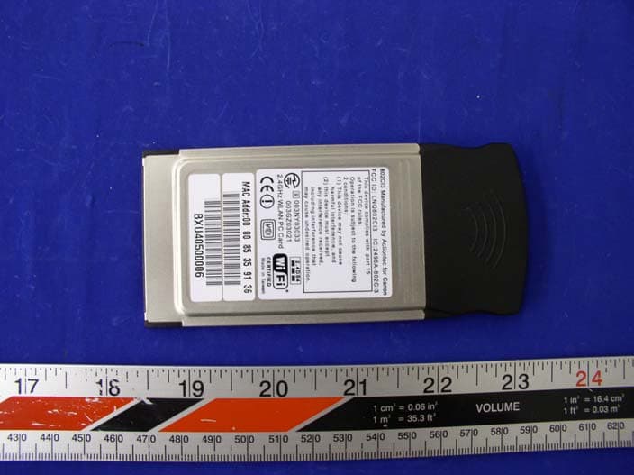
Click to zoom
Application Details
- Equipment Class
- DTS - Digital Transmission System
- Date of Grant
- Mar 11, 2004
- Application Purpose
- Original Equipment
- Date of Application
- Mar 11, 2004
- Equipment Note
- 802.11b Wireless PCMCIA Card
- Frequency Range
- 2412.00000000 - 2462.00000000
- Company
- Actiontec Electronics Inc
- Country
- United States
Documents & Files
Document Text
Text extracted from the exhibit documents filed with the FCC. Open a document above to read the original.
Users Manual
802CI3 User Manuel 2 Contents 1. Contents 2. Introduction 3. Wireless LAN Basics 4. Installation for Window 95 / 98 5. Troubleshooting 6. Technical specifications of 802CI3 2. Introduction Thank you for purchasing your Wireless LAN, 802CI3 PC Card. This manual will assist you with the installation procedure. The package you have received should contain the following items: • 802CI3 PC Card • User manual • Diskette containing Wireless LAN Management utility and drivers Note: if anything is missing, please contact your vendor The diskette contains the drivers and the program; this is used for managing the 802CI3 card and establishing the wireless connection with your Local Area Network. 3 3. Wireless LAN Basics Wireless LAN (Local Area Networks) systems offer a great number of advantages over a traditional, wired system. Wireless LANs (WLANs) are more flexible, easier to setup and manage and often more cost effective than their wired equivalence. Using radio frequency (RF) technology. WLANs transmit and receive data over the air, minimizing the need for wired connections. Thus, WLANs combine data connectivity with user mobility, and, through simplified configuration, enable movable LANs. With wireless LANs, users can access shared information without looking for a place to plug in and network managers can set up or augment networks without installing or moving wires. Wireless LANs offer the following productivity, convenience and cost advantages over traditional wired networks. • Mobility – Wireless LAN systems can provide LAN users with access to real-time information anywhere in their organization. This mobility supports productivity and service opportunities not possible with wired networks. • Installation Speed and Simplicity – Installing a wireless LAN system can be fast and easy and can eliminate the need to pull cable through walls and ceilings. • Installation Flexibility – wireless technology allows the network to go where wires cannot go. • Reduced Cost-of-Ownership – While the initial investment required for wireless LAN hardware might be higher than the cost of wired LAN hardware, overall installation expenses and life- cycle costs will be significantly lower. Long- term cost benefits are greatest in dynamic environments requiring frequent moves, adds, and changes. • Scalability – Wireless LAN systems can be configured in a variety of topologies to meet the needs of specific applications and installations. Configurations are easily changed and range from peer-to-peer networks suitable for a small number of users to full infrastructure networks of thousands of users that allows roaming over a broad area. 4. Installation for Windows 95 / 98 The following section will assist you to installing wireless LAN Adapter successfully. You will first install software (driver) and then insert the 802CI3 wireless LAN card, and finally set the network properties to accommodate resource sharing and select the type of wireless network that you wish to install. The 802CI3 can be easily be installed and used, without bothering to connect cables for keeping your computer to use network resources, as in case of wired LAN. 4.1 Installation Overview Here are some steps you will perform in establishing your wireless network connection: • Install the Access Point at first. AP is needed in case of Infrastructure network mode. • Install the software using the Installation Diskette. • Install the Wireless LAN Card (802CI3). • Install the network protocol(s) required to communicate on your network. Most likely you will need the TCP/IP protocol. 4 4.2 Installation Procedure of 802CI3 PC Card Note: Do not insert the PCMCI card until you are asked to do so, failure of which may result in unsuccessful installation of your PCMCIA WLAN card. Please follow the following steps one by one in order to install the PCMCIA card successfully. 1. Power on your computer and allow Windows 95 / 98 to load fully. 2. Be sure that there is no PCMCIA adapter inserted yet. 3. Insert the given Installation Diskette and then click on the A:\disk1\setup.exe. 4. Accept the license agreement. 5. Give the path of the destination folder. To set the path of your choice click on Browser and then click Next. 6. It takes a few seconds for copying the utility files and then click on Finish to complete the installation. 7. Insert the 802CI3 card into PCMCIA slot; windows will then prompt the required driver. 8. Locate the driver path Ex. A:\ and install the driver 9. Restart the PC and Click on the Control Panel and then on PC Card. Check whether it has PCMCIA card in one of the sockets or not. If you find 802CI3 PC Card in one of the sockets, it means the card is detected properly. 10. Check for the 802CI3 Wireless PCMCIA LAN Card by right clicking on My Computer using the mouse. Select the Device manager and then Network Adapters. If you find the sign on the adapter, it shows the installation is not successful. Select the adapter and click on Remove. Restart your computer after uninstalling the driver to make the changes effective. And refer to manual. 11. Right click on the Network Neighborhood using the mouse. 12. Select Properties from the pop up menu. The network box appears and you see the three main tables: Configuration, Identification, and Access Control. 13. Click on the Configuration tab and then click on the Add button. Select Network Component Type box appears. Click on the Protocol the click the Add button. 14. Select Network Protocols box appears. From the list of manufactures, click on Microsoft. From the list of network protocols list, select NetBEUI, then click OK. 15. The NetBEUI protocol is now installed. After clicking on OK return back to Network Component Type box. 16. Repeat the step 15 and 16 to add IPX/SPX protocol. 17. Repeat the step 15 and 16 to add TCP/IP protocol. 18. Click on the TCP/IP option for setting the IP address for your computer. You can select either Static OR DHCP setting. If you use the static IP s…
Text truncated - open the document above for the full version.
Block Diagram
Specifications of PCMCIA Type II 802.11b Card 4 802.11 Wireless LAN Block Diagram ISL3871IK18: Intersil, Wireless LAN integrated Medium Access Controller with Baseband Processor ISL3084: Intersil, 2.4GHz Voltage Controlled Oscillator ISL3684A: Intersil, 2.4GHz Direct Up/Down Converter Single chip PHY ISL3984: Intersil, 2.4GHz Power Amp and Detector Flash & SRAM PCMCIA
External Photos
Actiontec Electronics, Inc. FCC ID: LNQ802CI3A EXHIBIT C - EUT PHOTOGRAPHS EUT – Top View EUT – Bottom View
ID Label/Location Info
EXHIBIT A - FCC ID LABEL INFORMATION Proposed FCC ID Label Specifications : Text is black or white in color and is left justified. Labels are silk-screened and shall be “permanently affixed” at a conspicuous location on the EUT. Proposed Label Location on EUT Bottom Side of EUT/FCC ID Label FCC ID: I38-NA8300-001 This device complies with Part 15 o the FCC Rules. Operation is subject to the following two conditions: (1) this device may not cause harmful interference, and (2) this device must accept any interference received, including interference that may cause undesired operation. 2.1875" 1.0" FCC ID: LNQ802CI3A
Internal Photos
Actiontec Electronics, Inc. FCC ID: LNQ802CI3A EUT – Component View Actiontec Electronics, Inc. FCC ID: LNQ802CI3A EUT – Component View without Shielding EUT – Solder View
Operational Description
SPECIFICATIONS Of PCMCIA Type II 802.11b Card: 802CI3 Ver. 0.2 Date: 2/01/04 Specifications of PCMCIA Type II 802.11b Card 2 Contents: Device Overall Description 802.11 Wireless LAN - Features - Block Diagram - Modulation Methods - Channel Assignment - Security (WEP Key) - RF Characteristics - Software & OS support - Regulation - Interoperability - Operating Conditions Device Overall Description The 802CI3 is designed to provide wireless LAN function on a PCMCIA Type II Extended form factor. The wireless LAN function is based on Intersil Prism3 chipset, which implements the full IEEE802.11b standard date rates up to 11Mbps. Specifications of PCMCIA Type II 802.11b Card 3 802.11 Wireless LAN Features - Intersil Prism3 chipset - IEEE802.11 Direct Sequence Spread Spectrum (DSSS) - IEEE802.11 Standard Data Rates: 1, 2, 5.5 and 11Mbps - Full Implementation of the MAC Protocol Specified in IEEE Standards 802.11-1999 and 802.11b - Internal Encryption Engine Executes IEEE802.11 WEP - 128-bit WEP encryption, backward compatible with 64-bit solutions. - Support BSS (Infrastructure mode) and IBSS (Ad hoc mode). - Support BSS and IBSS operation under Distributed Coordination Function (DCF) and Point Coordination Function (PCF) - Support Pseudo IBSS mode which allows two computers to communicate in Ad Hoc configuration and allows backward compatibility with previous generation of Intersil products. - Onboard Diversity Antenna Switch - Onboard Microstrip Antenna Specification Compliance - IEEE 802.11b - PCMCIA spec. 5.1 Form factor - PCMCIA Type II Extended with 3.3V Keyed - Weight 1.4 oz - Dimension: 119mm x 54mm x 5mm (LxWxH) Specifications of PCMCIA Type II 802.11b Card 4 802.11 Wireless LAN Block Diagram ISL3871IK18: Intersil, Wireless LAN integrated Medium Access Controller with Baseband Processor ISL3084: Intersil, 2.4GHz Voltage Controlled Oscillator ISL3684A: Intersil, 2.4GHz Direct Up/Down Converter Single chip PHY ISL3984: Intersil, 2.4GHz Power Amp and Detector Flash & SRAM PCMCIA Specifications of PCMCIA Type II 802.11b Card 5 Modulation Methods Modulation spec. 1 Mbps DBPSK 802.11 2 Mbps DQPSK 802.11 5.5 Mbps CCK 802.11b 11 Mbps CCK 802.11b Channel Assignment Channel Frequency FCC IC ETSI Japan 1 2412MHz X X X X 2 2417MHz X X X X 3 2422MHz X X X X 4 2427MHz X X X X 5 2432MHz X X X X 6 2437MHz X X X X 7 2442MHz X X X X 8 2447MHz X X X X 9 2452MHz X X X X 10 2457MHz X X X X 11 2462MHz X X X X 12 2467MHz X X X X 13 2472MHz X X X X 14 2484MHz X Many countries and region are currently revising the channel assignment. Security (WEP Key) Support the IEEE 802.11b compatible 64 bit WEP in all data rate modes. Support 128 bit 128RC4 algorithm in all data rate modes. Specifications of PCMCIA Type II 802.11b Card 6 RF Characteristics RF Characteristics Minimum Typical Maximum Units Form Factor PCMCIA II Extended PC Interface 16-bit PCMCIA Plug and Play Compatible Yes Access Point Capable Yes Internal Antenna Impedance 50 ohms Ambient Operating Temperature Range 065 C Storage Temperature Range -20+85 C Supply Voltage (3.3 V only) 3.03.33.6 V RX Supply Current (at 3.3 V) 260 mA TX Supply Current (at 3.3 V) 290 mA 802.11 Sleep Supply Current 50 mA Initialization Supply Current 140 mA RX Adjacent Channel Rejection 43.042.642.0 dB RX Sensitivity, 1 Mbps -90-89 dBm RX Sensitivity, 2 Mbps -87-85 dBm RX Sensitivity, 5 Mbps -85-83 dBm RX Sensitivity, 11 Mbps -83-81 dBm Diversity Isolation 23.025.227.0 dB TX Output Power (including antenna gain) 13 dBm TX Carrier Suppression 27.0633.3434.95 dB TX Spectral Mask, 1st side-lobe -30 dBc TX Spectral Mask, 2nd side-lobe -50 dBc 1 Mbps Multipath Tolerance 290.0 290.0 290.0 802.11 2 Mbps Multipath Tolerance 290.0 290.0 290.0 802.11 5.5 Mbps Multipath Tolerance 164.0 164.0 164.0 802.11 11 Mbps Multipath Tolerance 75.0 81.0 85.0 802.11 Maximum input Level 4dbm Over-voltage protection +17dbm Dual Antenna Diversity, Short Preamble BBP SW Dual Antenna Diversity, Long Preamble BBP SW Preamble Length Short/Long SRAM 128K X 16 Serial Flash 128KX8 802.11 Compliance Compliant Note: Sensitivity based upon 1 kbyte packet length, 8% PER, single antenna driven, diversity enabled. Note: Adjacent channel rejection based upon 1 kbyte packet length, 8% PER, 25 MHz jammer offset. Note: Multipath tolerance based upon 1 kbyte packet length, 8% PER, signal level > -60 dBm, single antenna driven, diversity enabled, broadcast packets. Note: All measurements at the end of 6" of cable through Murata Connector with local diversity option. Specifications of PCMCIA Type II 802.11b Card 7 Software & OS support OS Driver Win95, OSR2 NDIS4 NT4 NDIS4 Win98 NDIS5 Windows Millennium NDIS5 Win2000 NDIS5 WinXP NDIS5.1 User Configuration Utility Available Regulation US FCC 15.247 Canada RSS 210 Europe EN 300 328-2: 2001 EN 301 489-17: 2002 EN 60950: 2002 Japan ARIB STD-T66 Others Upon request Interoperability Actiontec is an active member of Wireless Ethernet Compatibility Alliance (WECA). All Actiontec 802.11b Wireless products will be certified by WECA Wi-fi test to assure interoperability between vendors of 802.11b. Operating Conditions Voltage Range 3.3V +-0.3V Operating Temperature Range 0°C - 65°C Storage Temperature Range -20°C - 85°C Relative Humidity during Operating 95% Relative Humidity during Storage 95%
Operational Description
1 802CI3 Theory of Operation ISL3871IK18: Intersil, Wireless LAN integrated Medium Access Controller with Baseband Processor ISL3084: Intersil, 2.4GHz Voltage Controlled Oscillator ISL3684A: Intersil, 2.4GHz Direct Up/Down Converter Single chip PHY ISL3984: Intersil, 2.4GHz Power Amp and Detector The input signal to the radio is received through either one of the antennas. The selection of the antenna is performed through the operations of the ISL3871 BBP/MAC and the Diversity Switch. The received signal from the selected antenna is then fed to a bandpass filter (BPF). After filtering out these unwanted signals, the signal is routed to the ISL3684A Zero Intermediate Frequency (ZIF) chip, which serves as a direct down conversion transceiver. The local oscillator for the down conversion mixer is derived from the ISL3084 RF VCO. The RF LO frequency is phase locked by the synthesizer to the 44 MHz clock. The RF VCO operates at twice the channel frequency. Signals from ISL3684A are then fed to the BBP/MAC chip. 2 The MAC ISL3871 then processes the packet data and sends it on through the CF interface to the host computer. On the transmit signal path, data from the host computer is sent to the MAC through the CF interface. After being converted from digital to an analog signal in the ISL3871 BBP/MAC, the outputs are routed to the ISL3684A ZIF chip. The transmit output signal from the ZIF chip is then fed to the ISL3984 Power Amplifier. After the RF PA, the signal travels through a Transmit/Receive (T/R) Switch and a Bandpass Filter (BPF). There is approximately +14dBm of available transmit power at the antenna.
Parts List/Tune Up Info
2 01-0016-036J MYLAR MYLAR FOR BOTTOM COVER 1 2 01-0016-091G MYLAR FOR SHIELD COVER INSIDE 1 2 01-0018-053H HOUSING HOUSING FOR PRODUCT 1 2 02-0004-018W SPONGE METAL SHEET 1 2 03-0025-102W SHIELD COVER TOP COVER 1 2 03-0025-1187 SHIELD COVER SHIELD COVER 1 2 03-0025-124Z SHIELD COVER BOTTOM COVER 1 2 03-XXXX-XXX X CONDUCTIVE FOAM CONDUCTIVE FOAM FOR PRODUCT 2 3 52-0411-001L SMT IC 128K*16 SRAM BGA-48 1 U1. 3 53-1100-037Z SMT IC 2.85V REGULATOR 3 U6.7.14. 3 53-1100-0550 SMT IC 1.8V REGULATOR SOT-23.5 1 U16. 3 55-0306-014X SMT IC ISL3684AIR QFP-54 1 U11. 3 55-0306-015N SMT IC ISL3871IN18 TQFP-208 1 U5. 3 55-0310-002G SMT IC IF/RF POWER AMPLIFIER 1 U12 3 56-0110-023Y SMT IC IC FET SWITCH SC-70 2 U8.10. 3 56-0508-0019 SMT LED GREEN LED 1206 1 D4. 3 57-0200-033P SMT VCO ISL3084 VCO MLF-16 1 U15 3 57-0200-0398 SMT OSC 44MHZ +-20PPM 3V 7*5*1.3MM 1 U13. 3 57-0200-020N SMT OSC 44MHZ +/-20PPM 3V 5*7MM 0 3 64-0000-1414 SMT RES 0 OHM 5% 0402 0.06W 7 R4.R5.R12.R15.R28.R30.R33 3 64-1000-1411 SMT RES 100 OHM 5% 1/16W 0402 9 R25.R27.R31.R35.R43.R46.R48.R51.R53. 3 64-1001-242G SMT RES 1.0K OHM 1% 0402 0.06W 1 R71. 3 64-1002-241J SMT RES 10K OHM 1% 1/16W 0402 3 R19.R17.R18. 3 64-1005-131G SMT RES 10M OHM 5% 0603 1 R22 3 64-1009-141L SMT RES 10 OHM 5% 1/16W 0402 2 R20.R68. 3 64-1131-2416 SMT RES 1.13K OHM 1% 1/16W 0402 1 R23 3 64-1212-2416 SMT RES 12.1K OHM 1% 1/16W 0402 1 R16 3 64-1501-2415 SMT RES 1.5K OHM 1% 1/16W 0402 1 R7. 3 64-1801-1410 SMT RES 1.8K OHM 5% 1/16W 0402 1 R65 3 64-1912-241F SMT RES 19.1K OHM 1% 1/16W 0402 2 R9.R10. 3 64-2000-141Z SMT RES 200 OHM 5% 0402 1 R3. 3 64-2203-1419 SMT RES 220K OHM 5% 0402 1 R57 3 64-4300-141H SMT RES 430 OHM 5% 0402 4 R41.R45.R49.R52 3 64-4641-2419 SMT RES 4.64K OHM 1% 1/16W 0402 1 R50. 3 64-4702-XXXX SMT RES 100K OHM 5% 0402 1 R32 3 64-4709-142C SMT RES 47 OHM 5% 1/16W 0402 2 R24.R26 3 64-4990-241F SMT RES 499 OHM 1% 1/16W 0402 4 R42.R44.R47.R54. 3 64-5600-1412 SMT RES 560 OHM 5% 1/16W 0402 2 R11.R69. 3 64-9531-2413 SMT RES 9.53K OHM 1% 1/16W 0402 1 R8. 3 65-1005-902A SMT CAP CER 0.5PF 50V +/-0.1PF NPO 0402 1 C87 3 65-1010-9017 SMT CAP CER 1.0PF 50V +/-0.25PF NPO 0402 1 C50 3 65-1012-901W SMT CAP 1.2PF +-0.25PF 0402 NPO 50V 1 C151 3 65-1018-902N SMT CAP CER 1.8PF +/-0.25PF NPO 0402 50V 1 C56 3 65-1033-901G SMT CAP CER 3.3P 50V +/-0.25PF NPO 0402 2 C153.C154. 802CI3 Bill of Materials Feb. 04 2004 Page 1 of 2 3 65-1039-9028 SMT CAP 3.9PF +/-0.25PF 0402 50V NPO 3 C61.C82.C130. 3 65-1047-901N SMT CAP 4.7PF +-0.25PF 0402 50V 1 C54 3 65-1050-901N SMT CAP CER MONO 5PF 50V D NPO 0402 1 C37 3 65-1100-9018 SMT CAP 10PF +-5% 0402 50V 1 C115 3 65-1101-902U SMT CAP 100PF 50V J NPO 0402 3 C64.C71.C94 3 65-1102-8095 SMT CAP 1000PF/50V X7R 0603 K 2 C13.C15. 3 65-1102-902N SMT CAP CER 1000P 50V K X7R 0402 12 C23.C60.C68.C70.C75.C84.C89. C98.C101.C106.C114.C128 3 65-1104-805T SMT CAP CER 0.1UF 16V K X7R 0603 45 C2-C8.C10.C14.C18-C22.C24-C27.C29. C31.C33.C35.C36.C39-C42.C44-C49.C51-C53C57.C62.C63.C74.C76.C81.C86.C90.C103 3 65-1220-903D SMT CAP 22PF 50V J NPO 0402 1 C30 3 65-1221-901P SMT CAP 220PF +-5% 0402 25V 1 C116 3 65-1270-902Y SMT CAP CER MONO 27PF 50V J NPO 0402 4 C92.C93.C99.C104. 3 65-1271-902S SMT CAP CER MONO 270PF 50V J NPO 0402 1 C126 3 65-1300-9010 SMT CAP CER MONO 30PF 50V J NPO 0402 4 C100.C105.C107.C108 3 65-1470-901Z SMT CAP CER 47PF 25V J NPO 0402 2 C16.C69 3 65-1684-201A SMT CAP CER MONO 680NF 10V K X7R 0805 3 C72.C85.C123 3 65-1709-9014 SMT CAP CER 7PF +/-0.5PF NPO 50V 0402 11 C17.C65-C67.C73.C77-C79.C83.C97.C109 3 65-1822-901W SMT CAP CER MONO 8200PF 16V K X7R 0402 1 C125 3 65-1823-801X SMT CAP CER MONO 0.082UF 50V X7R 0603 1 C118. 3 65-2106-801D SMT CAP TANT 10UF 6.3V M ( 0805 ) 7 C9.C34.C38.C110.C129.C59.C11. 3 65-XXXX-XXX X SMT CAP 0.1UF 0402 1 C160 3 70-1109-101J SMT IND 1.0NH +/-0.3NH 300MA 0402 1 L20. 3 70-1229-1015 SMT IND 2.2NH +/-0.3NH 300MA 0402 2 L5.L6 3 70-1562-1026 SMT IND 560NH 10% 35MA 0603 1 L2. 3 70-2120-001U SMT BEAD 120 OHM/100M 0402 2 L16.18. 3 70-2200-039E FERRITTE BEAD 30 OHM @ 100MHZ 3KMA 0.03DCR 0805 6 L1.L3.L9.L10.L17.L4. 3 70-3100-008B SMT FILTER BAND PASS FILTE R 1 FL4 3 71-0900-003V TRANSFORMER BALUN TRANSFORMER 1 T1 3 74-2600-034Z SMT CONN 68PIN FOR 802CI2 1 P1. 2 45-0400-114M CRYSTAL 32.768KHZ CL:12.5PF 20PPM 2*6M/M 1 U4. 2 52-0607-036N SMT IC 128K*8 CMOS FLASH MEMORY TSOP-32 ( 8*14M 1 U2A. 2 65-1104-805T SMT CAP CER 0.1UF 16V K X7R 0603 1 C1. Page 2 of 2
RF Exposure Info
§1.1307(b)(1) & §2.1091 - RF EXPOSURE According to §15.247(b)(5) and §1.1307(b)(1), systems operating under the provisions of this section shall be operated in a manner that ensures that the public is not exposed to radio frequency energy level in excess of the Commission’s guidelines. According to §1.1310 and §2.1091 RF exposure is calculated. Limits for General Population/Uncontrolled Exposure Frequency Range (MHz) Electric Field Strength (V/m) Magnetic Field Strength (A/m) Power Density (mW/cm 2 ) Averaging Time (minute) Limits for General Population/Uncontrolled Exposure 0.3-1.34 614 1.63 *(100) 30 1.34-30 824/f 2.19/f *(180/f 2 ) 30 30-300 27.5 0.073 0.2 30 300-1500 / / f/1500 30 1500-100,000 / / 1.0 30 f = frequency in MHz * = Plane-wave equivalent power density MPE Prediction Predication of MPE limit at a given distance Equation from page 18 of OET Bulletin 65, Edition 97-01 S = PG/4πR² Where: S = power density P = power input to antenna G = power gain of the antenna in the direction of interest relative to an isotropic radiator R = distance to the center of radiation of the antenna Maximum peak output power at antenna input terminal: 10.73 (dBm ) Maximum peak output power at antenna input terminal: 11.83 (mW) Prediction distance: 1.2 (cm) Predication frequency: 2400 (MHz) Antenna Gain (typical): 1.5 (dBi) antenna gain: 1.4 (numeric) Power density at predication frequency at 1.2 cm: 0.92(mW/cm 2 ) MPE limit for uncontrolled exposure at prediction frequency: 1.0 (mW/cm 2 ) Test Result The EUT is a portable device. The power density level at 1.2cm is 0.92 mW/cm², which is below the uncontrolled exposure limit of 1.0mW/cm² at 2400 MHz.
Test Report
Note: This test report is specially limited to the above client company and product model only. It may not be duplicated without prior written consent of Bay Area Compliance Laboratory Corporation. This report must not be used by the client to claim product endorsement by NVLAP or any agency of the U.S. Government. FCC PART 15 EMI MEASUREMENT AND TEST REPORT For Actiontec Electronics, Inc. 760 North Mary Ave. Sunnyvale, CA 94086 FCC ID: LNQ802CI3A 2004-02-27 This Report Concerns: Original Report Equipment Type: 802.11b Wireless PCMCIA Card Test Engineer: Ming Jing / Report No.: R0402022 Test Date: 2004-02-12 Reviewed By: Ling Zhang / Prepared By: Bay Area Compliance Laboratory Corporation (BACL) 230 Commercial Street Sunnyvale, CA 94085 Tel: (408) 732-9162 Fax: (408) 732 9164 Actiontec Electronics, Inc. FCC ID: LNQ802CI3A Report # R0402022Rpt Page 2 of 33 FCC Part 15.247 Test Report TABLE OF CONTENTS GENERAL INFORMATION.......................................................................................................................................4 PRODUCT DESCRIPTION FOR EQUIPMENT UNDER TEST (EUT) ....................................................................................4 OBJECTIVE...................................................................................................................................................................4 RELATED SUBMITTAL(S)/GRANT(S).............................................................................................................................4 TEST METHODOLOGY..................................................................................................................................................4 TEST FACILITY.............................................................................................................................................................4 SYSTEM TEST CONFIGURATION ..........................................................................................................................6 JUSTIFICATION.............................................................................................................................................................6 EUT EXERCISE SOFTWARE..........................................................................................................................................6 SPECIAL ACCESSORIES.................................................................................................................................................6 SCHEMATICS / BLOCK DIAGRAM.................................................................................................................................6 EQUIPMENT MODIFICATIONS.......................................................................................................................................6 CONFIGURATION OF TEST SYSTEM..............................................................................................................................7 TEST SETUP BLOCK DIAGRAM.....................................................................................................................................7 SUPPORT EQUIPMENT LIST AND DETAILS....................................................................................................................8 EXTERNAL I/O CABLING LIST AND DETAILS...............................................................................................................8 SUMMARY OF TEST RESULTS ...............................................................................................................................9 §15.203 - ANTENNA REQUIREMENT....................................................................................................................10 STANDARD APPLICABLE............................................................................................................................................10 §15.207(A) - CONDUCTED EMISSIONS.................................................................................................................11 MEASUREMENT UNCERTAINTY..................................................................................................................................11 EUT SETUP................................................................................................................................................................11 SPECTRUM ANALYZER SETUP....................................................................................................................................11 TEST EQUIPMENT LIST AND DETAILS.........................................................................................................................11 TEST PROCEDURE......................................................................................................................................................11 SUMMARY OF TEST RESULTS.....................................................................................................................................12 CONDUCTED EMISSIONS TEST DATA.........................................................................................................................12 PLOT OF CONDUCTED EMISSIONS TEST DATA...........................................................................................................12 §15.209(A) - SPURIOUS EMISSION ........................................................................................................................15 STANDARD APPLICABLE............................................................................................................................................15 MEASUREMENT PROCEDURE......................................................................................................................................15 EQUIPMENT LISTS......................................................................................................................................................15 MEASUREMENT RESULT......…
Text truncated - open the document above for the full version.
Test Setup Photos
Actiontec Electronics, Inc. FCC ID: LNQ802CI3A EXHIBIT B - TEST SETUP PHOTOGRAPHS Conducted Emission - Front View Conducted Emission - Side View Actiontec Electronics, Inc. FCC ID: LNQ802CI3A Radiated Emission - Front View Radiated Emission - Rear View
Contact Information
Applicant
Brian Henrichs(President)
Test Firm
Bay Area Compliance LaboratoryJohn Chan
Technical Specifications
| # | Rule Parts | Frequency Range | Power Output |
|---|---|---|---|
| 1 | 15C | 2.41 GHz - 2.46 GHz | 11.80 mW |
Other Applications from Actiontec Electronics Inc

LNQWF672
Dec 26, 2025Wi-Fi 7 Outdoor Mesh AP
Equipment Class
DTS - Digital Transmission System
LNQ-WF670G
Dec 09, 2025Wi-Fi 7 Outdoor Mesh AP
Equipment Class
DTS - Digital Transmission SystemLNQ-WF815-2
Apr 14, 2024Tri-band Wi-Fi 6E Wireless AP
Equipment Class
DTS - Digital Transmission System
LNQ-WF825
Mar 24, 2024Tri-band Wi-Fi 7 Wireless AP
Equipment Class
6ID - 15E 6 GHz Low Power Indoor Access Point
LNQ-WF810G-2
Mar 23, 2024Wi-Fi 6E Mesh Extender
Equipment Class
DTS - Digital Transmission System