LNQ802DRN802.11a/b/g/n 3x3 Dual Radio PCIe Module
Actiontec Electronics Inc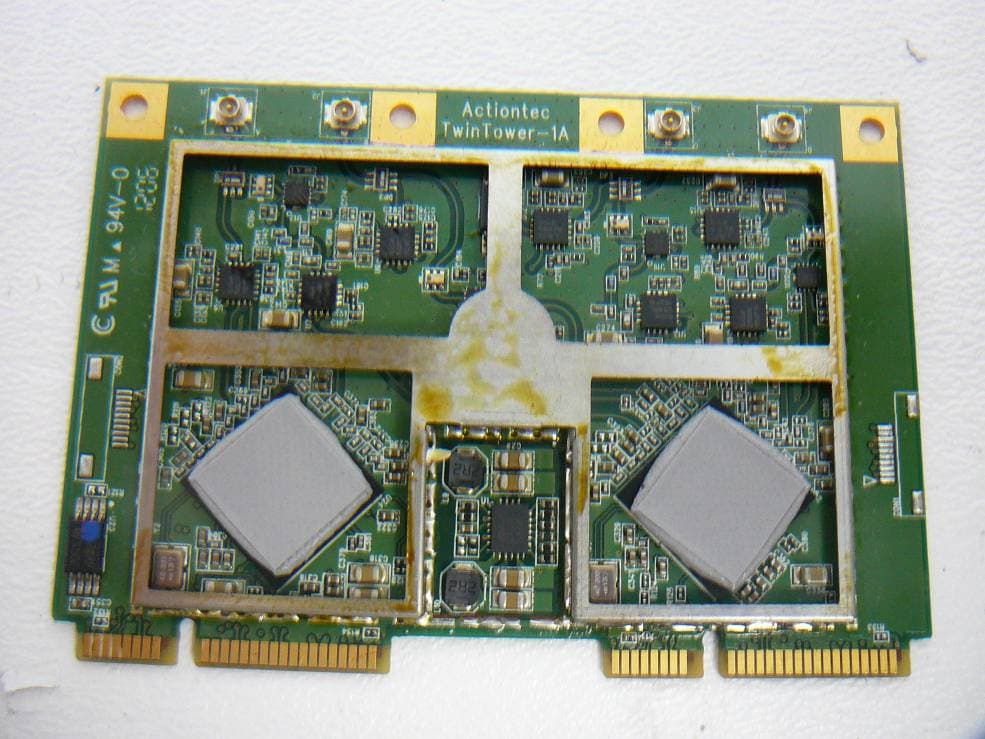
Click to zoom
Application Details
- Equipment Class
- NII - Unlicensed National Information Infrastructure TX
- Date of Grant
- Jun 12, 2012
- Application Purpose
- Original Equipment
- Date of Application
- Jun 12, 2012
- Equipment Note
- 802.11a/b/g/n 3x3 Dual Radio PCIe Module
- Frequency Range
- 5190.00000000 - 5230.00000000
- Company
- Actiontec Electronics Inc
- Country
- United States
Documents & Files
Document Text
Text extracted from the exhibit documents filed with the FCC. Open a document above to read the original.
Users Manual
1 Actiontec 802DRN Dual-Band Concurrent 802.11a/b/g/n 3x3 MIMO Dual-Radio PCIe Wireless Module User Guide 2 1. Description: Actiontec 802DRN is a Dual PCIe, Dual‐Band Concurrent 3x3 wireless local area network (WLAN) module designed to support high throughput data rates for both legacy 802.11b/g/n 2.4GHz and next generation 802.11 a/n 5GHz WLAN devices, simultaneously over a single set of dual‐band external antennas. The 802DRN provides the freedom of wireless connectivity with the performance, security, and manageability that businesses and consumers desire, in a single compact Dual PCIe module designed for maximum efficiency of space, power, and cost. A firmware‐based architecture is capable of supporting software upgrades to meet evolving industry standards. The 802DRN is complemented by drivers and networking tools for various embedded operating systems (e.g. Linux) . Extensive technical documentation on integration issues such as antenna design, customizing drivers , and management software can be provided on request. 2. Features: IEEE 802.11 b/g/n standards compliant in 2.4GHz IEEE 802.11 a/n standards compliant in 5GHz Direct Sequence Spread Spectrum (DSSS), Orthogonal Frequency Division Multiplexing (OFDM), and Multiple Input, Multiple Output (MIMO) baseband modulation (3x3) Dual-Band Concurrent 2.5GHz and 5GHz operation using a single set of external Dual-Band antennas Support for 20MHz and 40MHz channel widths, with 20/40 MHz coexistence Short guard interval for both 20MHz and 40MHz operation (Tx/Rx) Ultra-high data rate up to 450 Mbps (40MHz, 400ns GI) Auto fallback data rate under noisy environment Supports WEP (64-bit/128-bit), 802.1x, and WPA/WPA2 Flexible for design and antenna placement Low power consumption & Automatic power management to reduce power use Independent Tx Power Control on a per channel Automatic Tx Gain adjustment during temperature variations 3. App lications: Home and/or office wireless networking Wireless multimedia Wireless extension of existing wired network 4. Product Specifications: Form Factor Dual PCIe v1.1 (custom) Reference Clock 40 MHz +/- 10 ppm WLAN Standards IEEE 802.11b/g/n (2.4GHz) and 802.11a/n (5GHz) Antenna Connector IPEX Medium Access Protocol CSMA/CA (Collision Avoidance) with ACK Frequency Band 2.4~2.5 GHz and 4.9~5.825 GHz Number of Channels 2.4 GHz: up to 14 Channels depending on region; 5 GHz: up to 28 Channels, depending on region Modulation DSSS, OFDM, MIMO Supported 802.11 Data Rates 54, 48, 36, 24, 18, 12, 9, 6, 11, 5.5, 2, 1 Mbps Maximum PHY Rates (2.4GHz) 20 MHz: 130, 117, 104, 78, 52, 39, 26, 13 Mbps 40 MHz: 300, 270, 243, 216, 162, 108, 81, 54, 27 Mbps Maximum PHY Rates (5GHz) 20 MHz: 21.7, 43.3, 65, 86.7, 130, 173.3, 195, 216.7 Mbps 40 MHz: 45, 90, 135, 180, 270, 360, 405, 450 Mbps Antenna 3x External, Dual Band Voltage 3.3 VDC from host (power on waveform must be monotonic and Trise = 50us (Min.), 100 us (typ.), 100ms (max). There is no PCIe reset requirement at power-on. Power Consumption 3A worst-case peak current. Security WEP (64-bit/128-bit), 802.1x WPA/WPA2 (TKIP, AES) Operating System Linux Operation Environment Temperature: 0 ~ 40 к Humidity: 5~95% RH (non-condensing) Storage Environment Temperature: -10 ~ 70 к Humidity: 95% RH (non-condensing) 3 Regulatory Statements for 802DRN USA-Federal Communications Commission (FCC) This equipment has been tested and found to comply with the limits for a Class B digital device, pursuant to Part 15 of FCC Rules. These limits are designed to provide reasonable protection against harmful interference in a residential installation. This equipment generates, uses, and can radiate radio frequency energy. If not installed and used in accordance with the instructions, it may cause harmful interference to radio communications. However, there is no guarantee that interference will not occur in a particular installation. Any changes or modifications not expressly approved by the party responsible for compliance could void the user's authority to operate the equipment. This device complies with Part 15 of the FCC Rules. Operation is subject to the following two conditions: (1) This device may not cause harmful interference, and (2) This device must accept any interference received, including interference that may cause undesired operation. Caution: Exposure to Radio Frequency Radiation. To comply with FCC RF exposure compliance requirements, a separation distance of at least 20 cm must be maintained between the antenna of this device and all persons. This device must not be co-located or operating in conjunction with any other antenna or transmitter.
Cover Letter(s)
Actiontec Electronics, Inc. 760 North Mary Avenue • Sunnyvale • CA • 94085 • USA Phone (408) 752-7700 • Fax (408) 541-9003 • www.actiontec.com Solutions for the Digital Life™ FCC Confidential Authorization March 9, 2012 FEDERAL COMMUNICATIONS COMMISSIONS Authorization and Evaluation Division 7435 Oakland Mills Road Columbia, MD 21046 Subject: Confidentiality Request regarding application for certification of FCC ID: LNQ802DRN In accordance with Sections 0.457 and 0.459 of the Commission’s Rules, Actiontec Electronics, Inc., hereby requests long-term confidential treatment of information accompanying this application as outlined below: Block Diagram Schematics Circuit Description Antenna Information The above materials contain proprietary and confidential information not customarily released to the public. The public disclosure of these materials provides unjustified benefits to its competitors in the market. Sincerely Yours, Angela Yao / Sr. Program Manager Actiontec Electronics, Inc. 760 North Mary Ave., Sunnyvale, CA 94085 Phone(408) 752-7700 [email protected]
Cover Letter(s)
Actiontec Electronics, Inc. 760 North Mary Avenue • Sunnyvale • CA • 94085 • USA Phone (408) 752-7700 • Fax (408) 541-9003 • www.actiontec.com Broadband Technology Made Easy Transmitter Modular Approval Letter Date: February 29, 2012 Actiontec 802DRN - 802.11a/b/g/n 3x3 Dual-Radio PCIe Module FCC ID: LNQ802DRN is seeking FCC Authorization as a modular transmitter. The EUT meets the requirements for modular approval as detailed in FCC Public Notice DA 00-1407 ‘Part 15 Unlicensed Modular Transmitter Approval’. Compliance to each of the requirements is described below – 1. The modular transmitter must have its own RF shielding. - The EUT has its own RF shielding. 2. The modular transmitter must have buffered modulation/data inputs. - The EUT has buffered data inputs to insure compliance with Part 15 requirements. 3. The modular transmitter must have its own power supply regulator. - The EUT has its own power supply regulator. 4. The modular transmitter must comply with the antenna requirements of section 15.203 and 15.204(c). - The EUT meets the FCC antenna requirements. 5. The modular transmitter must be tested in a stand-alone configuration. - The EUT was tested in a Marvell Access Point (Model: AP-8764DR1) as a stand-alone module. 6. The modular transmitter must be labeled with its own FCC ID number. - The EUT is labeled with its own FCC ID number. 7. The modular transmitter must comply with any specific rule or operating requirements and the manufacture must provide adequate instruction along with the module to explain any such requirements. - The EUT is compliant with all applicable FCC rules. 8. The modular transmitter must comply with any applicable RF exposure requirements. - The EUT is compliant with all applicable RF exposure requirements. Sincerely, Angela Yao/Sr. Program Manager Actiontec Electronics, Inc. 760 North Mary Ave., Sunnyvale, CA 94085 408-752-7700
Cover Letter(s)
Actiontec Electronics, Inc. 760 North Mary Avenue • Sunnyvale • CA • 94085 • USA Phone (408) 752-7700 • Fax (408) 541-9003 • www.actiontec.com Solutions for the Digital Life™ Declaration Letter March 9, 2012 FEDERAL COMMUNICATIONS COMMISSIONS Authorization and Evaluation Division 7435 Oakland Mills Road Columbia, MD 21046 Re: FCC ID: LNQ802DRN To whom it may concern: We, Actiontec Electronics, Inc., hereby declare that 802DRN uses MIMO 3x3 antennas on J1, J2 and J3 connectors only. J4 will not be installed connector and Path D will be S/W disabled in production. There will be no third party’s software or configuration tool to program the device out of compliance of the technical rules under which it has been certified. Sincerely Yours, Angela Yao / Sr. Program Manager Actiontec Electronics, Inc. 760 North Mary Ave., Sunnyvale, CA 94085 Phone(408) 752-7700 [email protected]
External Photos
Actiontec Electronics, Inc. FCC ID: LNQ802DRN Report Number: R1203021-247 Page 255 of 259 FCC Part 15.247 Test Report 15 Exhibit C - EUT Photographs 15.1 EUT–Top View with Heat Sink 15.2 EUT–Top View with Heat Sink and Shielding Removed Actiontec Electronics, Inc. FCC ID: LNQ802DRN Report Number: R1203021-247 Page 256 of 259 FCC Part 15.247 Test Report 15.3 EUT–Top View with Heat Sink, Shielding and Foam Removed 15.4 EUT–Bottom View Actiontec Electronics, Inc. FCC ID: LNQ802DRN Report Number: R1203021-247 Page 257 of 259 FCC Part 15.247 Test Report 15.5 EUT–Front View with Antenna placement shown 15.6 Galtronics Antennas Left Antenna P/N: 02102140-05243-3 Ri ght Antenna P/N: 02102140-05243-1 Front Antenna P/N: 02102140-05243-2
ID Label/Location Info
Actiontec Electronics, Inc. FCC ID: LNQ802DRN Report Number: R1203021-247 Page 249 of 259 FCC Part 15.247 Test Report 13 Exhibit A - FCC ID Label Information 13.1 FCC ID Label Requirements As Per FCC §2.925, (a) Each equipment covered in an application for equipment authorization shall bear a nameplate or label listing the following: (1) FCC Identifier consisting of the two elements in the exact order specified in §2.926. The FCC Identifier shall be preceded by the term FCC ID in capital letters on a single line, and shall be of a type size large enough to be legible without the aid of magnification. Example: FCC ID: XXX123 XXX—Grantee Code 123—Equipment Product Code As Per FCC §15.19 (a) In addition to the requirements in part 2 of this chapter, a device subject to certification, or verification shall be labeled as follows: (3) All other devices shall bear the following statement in a conspicuous location on the device: This device complies with part 15 of the FCC Rules. Operation is subject to the following two conditions: (1) This device may not cause harmful interference, and (2) this device must accept any interference received, including interference that may cause undesired operation. (5) When the device is so small or for such use that it is not practicable to place the statement specified under paragraph (a) of this section on it, the information required by this paragraph shall be placed in a prominent location in the instruction manual or pamphlet supplied to the user or, alternatively, shall be placed on the container in which the device is marketed. However, the FCC identifier or the unique identifier, as appropriate, must be displayed on the device. 13.2 FCC ID Label Content As per FCC §15.19 (b) (4), the label shall not be a stick-on, paper label. The label on these products shall be permanently affixed to the product and shall be readily visible to the purchaser at the time of purchase, as described in Section 2.925(d) of this chapter. "Permanently affixed" means that the label is etched, engraved, stamped, silk-screened, indelibly printed, or otherwise permanently marked on a permanently attached part of the equipment or on a nameplate of metal, plastic, or other material fastened to the equipment by welding, riveting, or a permanent adhesive. The label must be designed to last the expected lifetime of the equipment in the environment in which the equipment may be operated and must not be readily detachable. Actiontec Electronics, Inc. FCC ID: LNQ802DRN Report Number: R1203021-247 Page 250 of 259 FCC Part 15.247 Test Report 13.3 FCC ID Label Location on EUT Label here
Internal Photos
Actiontec Electronics, Inc. FCC ID: LNQ802DRN Report Number: R1203021-247 Page 255 of 259 FCC Part 15.247 Test Report 15 Exhibit C - EUT Photographs 15.1 EUT–Top View with Heat Sink 15.2 EUT–Top View with Heat Sink and Shielding Removed Actiontec Electronics, Inc. FCC ID: LNQ802DRN Report Number: R1203021-247 Page 256 of 259 FCC Part 15.247 Test Report 15.3 EUT–Top View with Heat Sink, Shielding and Foam Removed 15.4 EUT–Bottom View Actiontec Electronics, Inc. FCC ID: LNQ802DRN Report Number: R1203021-247 Page 257 of 259 FCC Part 15.247 Test Report 15.5 EUT–Front View with Antenna placement shown 15.6 Galtronics Antennas Left Antenna P/N: 02102140-05243-3 Ri ght Antenna P/N: 02102140-05243-1 Front Antenna P/N: 02102140-05243-2
RF Exposure Info
1 FCC §15.203 – Antenna Requirements 1.1 Applicable Standard According to FCC §15.203, an intentional radiator shall be designed to ensure that no antenna other than that furnished by the responsible party shall be used with the device. The use of a permanently attached antenna or of an antenna that uses a unique coupling to the intentional radiator shall be considered sufficient to comply with the provisions of this Section. The manufacturer may design the unit so that a broken antenna can be replaced by the user, but the use of a standard antenna jack or electrical connector is prohibited. And according to FCC §15.247 (b)(4), if transmitting antennas of directional gain greater than 6 dBi are used the power shall be reduced by the amount in dB that the directional gain of the antenna exceeds 6 dBi. 1.2 Antenna List The antenna used on the device has a unique connector – U.F.L – and the antenna gain is less then 6dBi, therefore the antenna used fulfilled the antenna requirement above. EUT has two configurations, one with three Galtronics antennas, one with three Airgain antennas, since Galtronics antennas has higher gain with the same type, therefore only Galtronics antenna was tested with the unit during radiated emissions. Please refer to the below pictures for detail: Manufacture/Antenna Model Antenna Product Number/ Antenna Model Antenna Gain (dBi) Galtronics 02102140-05243-1 3.5 (at 2.4GHz) 4.21 (at 5GHz) Galtronics 02102140-05243-2 5.59 (at 2.4GHz) 4.82 (at 5GHz) Galtronics 02102140-05243-3 3.5 (at 2.4GHz) 4.21 (at 5GHz) Airgain M2450DLCB 3.5 (at 2.4 GHz) 4.0 (at 5 GHz) Airgain N2420DS 3.1 (at 2.44 GHz) 3.2 (at 5.2 GHz) Left Antenna P/N: 02102140-05243-3 Ri ght Antenna P/N: 02102140-05243-1 Front Antenna P/N: 02102140-05243-2 Testing configuration with Galtronics Antennas Tested Galtronics Antennas Airgain M2450DLCB Antennas Airgain N2420DS Antenna
Test Report
Note: This test report is prepared for the customer shown above and for the device described herein. It may not be duplicated or used in part without prior written consent from Bay Area Compliance Laboratories Corp. This report must not be used by the customer to claim product certification, approval, or endorsement by A2LA*, NIST, or any agency of the Federal Government. * This report may contain data that are not covered by the A2LA accreditation and are marked with an asterisk “*” (Rev.2) FCC PART 15.407 TEST AND MEASUREMENT REPORT For Actiontec Electronics, Inc. 760 N. Mary Avenue, Sunnyvale, CA 94085, USA FCC ID: LNQ802DRN Model: 802DRN Report Type: Original Report Product Type: 802.11 a/b/g/n WLAN Module Prepared By: Wei Sun Report Number: R1203021-407 Report Date: 2012-06-04 Reviewed By: Victor Zhang EMC/RF Lead Bay Area Compliance Laboratories Corp. 1274 Anvilwood Ave. Sunnyvale, CA 94089, USA Tel: (408) 732-9162 Fax: (408) 732-9164 Actiontec Electronics, Inc. FCC ID: LNQ802DRN Report Number: R1203021-407 Page 2 of 133 FCC Part 15.407 Test Report TABLE OF CONTENTS 1 GENERAL DESCRIPTION......................................................................................................................................... 6 1.1 PRODUCT DESCRIPTION FOR EQUIPMENT UNDER TEST (EUT)................................................................................. 6 1.2 MECHANICAL DESCRIPTION OF EUT ....................................................................................................................... 6 1.3 OBJECTIVE............................................................................................................................................................... 6 1.4 RELATED SUBMITTAL(S)/GRANT(S) ........................................................................................................................ 6 1.5 TEST METHODOLOGY.............................................................................................................................................. 6 1.6 MEASUREMENT UNCERTAINTY...............................................................................................................................6 1.7 TEST FACILITY........................................................................................................................................................ 7 2 SYSTEM TEST CONFIGURATION .......................................................................................................................... 8 2.1 JUSTIFICATION......................................................................................................................................................... 8 2.2 EUT EXERCISE SOFTWARE...................................................................................................................................... 8 2.3 EQUIPMENT MODIFICATIONS................................................................................................................................... 8 2.4 SPECIAL ACCESSORIES............................................................................................................................................ 8 2.5 LOCAL SUPPORT EQUIPMENT.................................................................................................................................. 8 2.6 POWER SUPPLY AND LINE FILTERS.......................................................................................................................... 8 2.7 EUT INTERNAL CONFIGURATION............................................................................................................................ 8 2.8 EXTERNAL I/O CABLING LIST AND DETAILS........................................................................................................... 9 3 SUMMARY OF TEST RESULTS ............................................................................................................................. 10 4 FCC §15.407(F), §2.1091 - RF EXPOSURE.............................................................................................................. 11 4.1 APPLICABLE STANDARD........................................................................................................................................ 11 4.2 MPE PREDICTION.................................................................................................................................................. 11 4.3 MPE RESULTS....................................................................................................................................................... 11 5 FCC §15.203 – ANTENNA REQUIREMENTS........................................................................................................ 12 5.1 APPLICABLE STANDARD........................................................................................................................................ 12 5.2 ANTENNA LIST...................................................................................................................................................... 12 6 FCC §15.207 - AC POWER LINE CONDUCTED EMISSIONS........................................................................... 14 6.1 APPLICABLE STANDARDS...................................................................................................................................... 14 6.2 TEST SETUP........................................................................................................................................................... 14 6.3 TEST PROCEDURE.................................................................................................................................................. 14 6.4 TEST SETUP BLOCK DIAGRAM...............................................................................................................................15 6.5 CORRECTED AMPLITUDE & MARGIN CALCULATION.......................................................................…
Text truncated - open the document above for the full version.
Test Setup Photos
Actiontec Electronics, Inc. FCC ID: LNQ802DRN Report Number: R1203021-407 Page 121 of 128 FCC Part 15.407 Test Report 15 Exhibit B - Test Setup Photographs 15.1 Conducted Emission Front View 15.2 Conducted Emission Side View Actiontec Electronics, Inc. FCC ID: LNQ802DRN Report Number: R1203021-407 Page 122 of 128 FCC Part 15.407 Test Report 15.3 Radiated Emission below 1GHz Front View 15.4 Radiated Emission below 1 GHz Rear View Actiontec Electronics, Inc. FCC ID: LNQ802DRN Report Number: R1203021-407 Page 123 of 128 FCC Part 15.407 Test Report 15.5 Radiated Emission above 1 GHz Front View 15.6 Radiated Emission above 1 GHz Rear View Actiontec Electronics, Inc. FCC ID: LNQ802DRN Report Number: R1203021-407 Page 124 of 128 FCC Part 15.407 Test Report 15.7 Conducted Test
Contact Information
Applicant
Brian Henrichs(President)
Test Firm
Bay Area Compliance LaboratoryJohn Chan
Technical Specifications
| # | Rule Parts | Frequency Range | Power Output |
|---|---|---|---|
| 3 | 15E | 5.19 GHz - 5.23 GHz | 43.00 mW |
Other Applications from Actiontec Electronics Inc

LNQWF672
Dec 26, 2025Wi-Fi 7 Outdoor Mesh AP
Equipment Class
DTS - Digital Transmission System
LNQ-WF670G
Dec 09, 2025Wi-Fi 7 Outdoor Mesh AP
Equipment Class
DTS - Digital Transmission SystemLNQ-WF815-2
Apr 14, 2024Tri-band Wi-Fi 6E Wireless AP
Equipment Class
DTS - Digital Transmission System
LNQ-WF825
Mar 24, 2024Tri-band Wi-Fi 7 Wireless AP
Equipment Class
6ID - 15E 6 GHz Low Power Indoor Access Point
LNQ-WF810G-2
Mar 23, 2024Wi-Fi 6E Mesh Extender
Equipment Class
DTS - Digital Transmission System