LNQ802MRG802.11b/g Wireless Modular
Actiontec Electronics Inc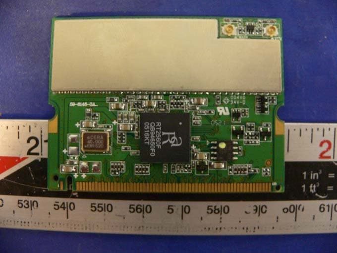
Click to zoom
Application Details
- Equipment Class
- DTS - Digital Transmission System
- Date of Grant
- Oct 11, 2005
- Application Purpose
- Original Equipment
- Date of Application
- Oct 11, 2005
- Equipment Note
- 802.11b/g Wireless Modular
- Frequency Range
- 2412.00000000 - 2462.00000000
- Company
- Actiontec Electronics Inc
- Country
- United States
Documents & Files
Document Text
Text extracted from the exhibit documents filed with the FCC. Open a document above to read the original.
Users Manual
Q802MKG User’s Manual 2 Driver Installation 1 . Go to the directory where the Wireless Adapter Installation stored, then double-click Setup.exe to begin the installation. 3. RALINK Wireless Network Card Setup will install the driver on your system, click Next to continue. 3 4. Select the Country Channel, and click Next to continue. 4 5. The installation is now complete. Please click Finish. 6. When you complete the installation, the utility icon will appear on the system tray. You could double-click it to configure wireless network settings 5 Uninstalling the Wireless LAN Card 1. For uninstalling the Wireless LAN Card, please go to: Start -> Programs -> Ralink -> RT2500 under Windows environment. Then click Uninstall. 2. Select Remove to uninstall the Wireless LAN Card. 6 3. The Confirm Uninstall screen will display, click OK to confirm. 4. Wait for removing the utility. 5. After completing the uninstallation, click OK. 7 Configuring the Wireless LAN Card Double-click the utility icon in your system tray to begin the utility configuration. Connecting to an existing network Select Site Survey Tab, all available Access Points would be listed. Click on the desired Access Point, and click Connect to connect. 8 Configuration z Profile The Profile Tab allows you to set values for all parameters by selecting a previously defined profile. To create a profile, click Add, type a profile name and set the corresponding parameters. If one of the profiles is no longer used, you may remove it by clicking the Delete button. After changing parameters, click the Activate button to take effect. You can have multiple profiles and modify the profile at any time. z Link Status 9 Status The field shows the association status to available Access Point with SSID<->MAC address of the Access Point. Current Channel Shows the channel on which the connection is made. Current Tx Rate Shows the highest transmit rate of the current association. Throughput (Kbits/sec) This displays the instantaneous wireless Receive and Transmit throughput in Kbits per second. Link Quality / Signal Strength The Link Quality and Signal Strength bar graph is only active when the node is in Infrastructure Mode. The bar graph displays the quality and strength of the link between the node and its Access Point. z Site Survey Site Survey Tab lists the features of the available Access Points within range of the Wireless Adapter's signal. Click on the desired Access Point, and click Connect to connect. You may click Rescan to refresh the list. 10 Add to Profile You may select an Access Point, and click Add to Profile to include it to Profile List. Under Add Profile screen / System Configuration Tab, you may set Power Saving Mode, Network Type, Transmit Power, RTS Threshold, and Fragment Threshold. Under Add Profile screen / Authentication vs. Security Tab, you may set Authentication Type, Encryption Type, WPA Pre-Shared Key, and Wep Key. Click OK when you have finished the settings. Or click Cancel to abort your new settings for Add to Profile. 11 After fishing the Add Profile, Check Profile Tab, you may find the new added profile in Profile List. 12 z Statistics The Statistics Tab provides information about the Transmit and Receive frames. z Advance The Configuration Utility also offers the advanced configuration for user to set the Wireless Adapter under certain network environment. These advanced options include Wireless Mode, Adhoc Mode, TX Burst, B/G Protection, Tx Rate, and Turn Off RF. 13 z About About Tab shows the product version including the detail of Configuration Utility Version, Driver Version, EEPROM Version, and NIC MAC Address. Federal Communication Commission Interference Statement This equipment has been tested and found to comply with the limits for a Class B digital device, pursuant to Part 15 of the FCC Rules. These limits are designed to provide reasonable protection against harmful interference in a residential installation. This equipment generates, uses and can radiate radio frequency energy and, if not installed and used in accordance with the instructions, may cause harmful interference to radio communications. However, there is no guarantee that interference will not occur in a particular installation. If this equipment does cause harmful interference to radio or television reception, which can be determined by turning the equipment off and on, the user is encouraged to try to correct the interference by one of the following measures: - Reorient or relocate the receiving antenna. - Increase the separation between the equipment and receiver. - Connect the equipment into an outlet on a circuit different from that to which the receiver is connected. - Consult the dealer or an experienced radio/TV technician for help. This device complies with Part 15 of the FCC Rules. Operation is subject to the following two conditions: (1) This device may not cause harmful interference, and (2) this device must accept any interference received, including interference that may cause undesired operation. FCC Caution: Any changes or modifications not expressly approved by the party responsible for compliance could void the user's authority to operate this equipment. IMPORTANT NOTE: FCC Radiation Exposure Statement: This equipment complies with FCC radiation exposure limits set forth for an uncontrolled environment. This equipment should be installed and operated with minimum distance 20cm between the radiator & your body. This transmitter must not be co-located or operating in conjunction with any other antenna or transmitter. This device is intended only for OEM integrators under the following conditions: 1) The antenna must be installed such that 20 cm is maintained between the antenna and users, and 2) The transmitter module may not be co-located with any other transmitter or antenna. As long as 2 conditions above are met, further transmitter test will not be required. However, the OEM integrator is still responsible for testing their …
Text truncated - open the document above for the full version.
External Photos
EXHIBIT C - EUT EXTERNAL PHOTOHS EUT – Component View EUT – Solder View EUT– Antenna View
ID Label/Location Info
EXHIBIT A - FCC ID LABEL INFORMATION Proposed FCC ID Label Specifications: Text is black or white in color and is left justified. Labels are silk- screened and shall be “permanently affixed” at a conspicuous location on the EUT. Proposed Label Location on EUT EUT Solder View / Proposed Label location FCC ID: LNQ802MRG
Internal Photos
EXHIBIT C - EUT INTERNAL PHOTOHS EUT – Component View EUT – Solder View EUT – Cover off View
Operational Description
FCC ID: RUJ-Q802MKG Report No.: RF930629L08 Operational Description This device is a 2.4GHz MiniPCI 802.11g Wireless LAN Card which operates in the 2.4GHz frequency spectrum with throughput of up to 54Mbps which OFDM technique will be applied. If the signal to noise radio is too poor which could not support 54Mbps, the 11Mbps data rate with CCK technique will be applied. The transmitter of the EUT is powered by host equipment and connected with managing equipment through Mini PCI interface. The antennas are PIFA antenna with UFL connector. Under normal use condition, the user has to keep at least 20cm separation distance between radiator and the body of the user. The other instruction, please have a look at the users manual.
Schematics
Q802MKG User’s Manual 2 Driver Installation 1 . Go to the directory where the Wireless Adapter Installation stored, then double-click Setup.exe to begin the installation. 3. RALINK Wireless Network Card Setup will install the driver on your system, click Next to continue. 3 4. Select the Country Channel, and click Next to continue. 4 5. The installation is now complete. Please click Finish. 6. When you complete the installation, the utility icon will appear on the system tray. You could double-click it to configure wireless network settings 5 Uninstalling the Wireless LAN Card 1. For uninstalling the Wireless LAN Card, please go to: Start -> Programs -> Ralink -> RT2500 under Windows environment. Then click Uninstall. 2. Select Remove to uninstall the Wireless LAN Card. 6 3. The Confirm Uninstall screen will display, click OK to confirm. 4. Wait for removing the utility. 5. After completing the uninstallation, click OK. 7 Configuring the Wireless LAN Card Double-click the utility icon in your system tray to begin the utility configuration. Connecting to an existing network Select Site Survey Tab, all available Access Points would be listed. Click on the desired Access Point, and click Connect to connect. 8 Configuration z Profile The Profile Tab allows you to set values for all parameters by selecting a previously defined profile. To create a profile, click Add, type a profile name and set the corresponding parameters. If one of the profiles is no longer used, you may remove it by clicking the Delete button. After changing parameters, click the Activate button to take effect. You can have multiple profiles and modify the profile at any time. z Link Status 9 Status The field shows the association status to available Access Point with SSID<->MAC address of the Access Point. Current Channel Shows the channel on which the connection is made. Current Tx Rate Shows the highest transmit rate of the current association. Throughput (Kbits/sec) This displays the instantaneous wireless Receive and Transmit throughput in Kbits per second. Link Quality / Signal Strength The Link Quality and Signal Strength bar graph is only active when the node is in Infrastructure Mode. The bar graph displays the quality and strength of the link between the node and its Access Point. z Site Survey Site Survey Tab lists the features of the available Access Points within range of the Wireless Adapter's signal. Click on the desired Access Point, and click Connect to connect. You may click Rescan to refresh the list. 10 Add to Profile You may select an Access Point, and click Add to Profile to include it to Profile List. Under Add Profile screen / System Configuration Tab, you may set Power Saving Mode, Network Type, Transmit Power, RTS Threshold, and Fragment Threshold. Under Add Profile screen / Authentication vs. Security Tab, you may set Authentication Type, Encryption Type, WPA Pre-Shared Key, and Wep Key. Click OK when you have finished the settings. Or click Cancel to abort your new settings for Add to Profile. 11 After fishing the Add Profile, Check Profile Tab, you may find the new added profile in Profile List. 12 z Statistics The Statistics Tab provides information about the Transmit and Receive frames. z Advance The Configuration Utility also offers the advanced configuration for user to set the Wireless Adapter under certain network environment. These advanced options include Wireless Mode, Adhoc Mode, TX Burst, B/G Protection, Tx Rate, and Turn Off RF. 13 z About About Tab shows the product version including the detail of Configuration Utility Version, Driver Version, EEPROM Version, and NIC MAC Address. Federal Communication Commission Interference Statement This equipment has been tested and found to comply with the limits for a Class B digital device, pursuant to Part 15 of the FCC Rules. These limits are designed to provide reasonable protection against harmful interference in a residential installation. This equipment generates, uses and can radiate radio frequency energy and, if not installed and used in accordance with the instructions, may cause harmful interference to radio communications. However, there is no guarantee that interference will not occur in a particular installation. If this equipment does cause harmful interference to radio or television reception, which can be determined by turning the equipment off and on, the user is encouraged to try to correct the interference by one of the following measures: - Reorient or relocate the receiving antenna. - Increase the separation between the equipment and receiver. - Connect the equipment into an outlet on a circuit different from that to which the receiver is connected. - Consult the dealer or an experienced radio/TV technician for help. This device complies with Part 15 of the FCC Rules. Operation is subject to the following two conditions: (1) This device may not cause harmful interference, and (2) this device must accept any interference received, including interference that may cause undesired operation. FCC Caution: Any changes or modifications not expressly approved by the party responsible for compliance could void the user's authority to operate this equipment. IMPORTANT NOTE: FCC Radiation Exposure Statement: This equipment complies with FCC radiation exposure limits set forth for an uncontrolled environment. This equipment should be installed and operated with minimum distance 20cm between the radiator & your body. This transmitter must not be co-located or operating in conjunction with any other antenna or transmitter. This device is intended only for OEM integrators under the following conditions: 1) The antenna must be installed such that 20 cm is maintained between the antenna and users, and 2) The transmitter module may not be co-located with any other transmitter or antenna. As long as 2 conditions above are met, further transmitter test will not be required. However, the OEM integrator is still responsible for testing their …
Text truncated - open the document above for the full version.
Test Report
Note: The test report is specially limited to the above company and this particular sample only. It may not be duplicated without prior written consent of Bay Area Compliance Laboratory Corporation. This report must not be used by the client to claim product certification, approval, or endorsement by NVLAP, NIST or any agency of the US Government. FCC PART 15.247 EMI MEASUREMENT AND TEST REPORT For Actiontec Electronics, Inc. 760 N. Mary Avenue, Sunnyvale, CA 94085 FCC ID: LNQ802MRG This Report Concerns: Original Report Equipment Type: 802.11b/g Wireless Modular Test Engineer: Oscar Au Report No.: R0509211 Report Date: 2005-09-28 Reviewed By: Daniel Deng Prepared By: Bay Area Compliance Laboratory Corporation 230 Commercial Street Sunnyvale, CA 94085 Tel (408) 732-9162 Fax (408) 732-9164 Actiontec Electronics, Inc. FCC ID: LNQ802MRG Report # R0509211Rpt Page 2 of 73 FCC Part 15.247Test Report TABLE OF CONTENTS GENERAL INFORMATION.......................................................................................................................................4 PRODUCT DESCRIPTION FOR EQUIPMENT UNDER TEST (EUT) ....................................................................................4 OBJECTIVE...................................................................................................................................................................4 RELATED SUBMITTAL(S)/GRANT(S).............................................................................................................................4 TEST METHODOLOGY..................................................................................................................................................4 TEST FACILITY.............................................................................................................................................................4 SYSTEM TEST CONFIGURATION ..........................................................................................................................6 JUSTIFICATION.............................................................................................................................................................6 SCHEMATICS AND BLOCK DIAGRAM............................................................................................................................6 EQUIPMENT MODIFICATIONS.......................................................................................................................................6 LOCAL SUPPORT EQUIPMENT.......................................................................................................................................6 EXTERNAL I/O CABLING LIST AND DETAILS...............................................................................................................6 POWER SUPPLY AND LINE FILTERS..............................................................................................................................6 CONFIGURATION OF TEST SYSTEM..............................................................................................................................7 TEST SETUP BLOCK DIAGRAM.....................................................................................................................................7 SUMMARY OF TEST RESULTS FOR FCC PART 15.247 .....................................................................................8 §1.1307(B)(1) & §2.1091 - RF EXPOSURE.................................................................................................................9 ANTENNA REQUIREMENT ....................................................................................................................................10 §15.207(A) - CONDUCTED EMISSION...................................................................................................................11 LIMITS OF CONDUCTED EMISSION MEASUREMENT...................................................................................................11 TEST SETUP................................................................................................................................................................11 TEST EQUIPMENT LIST AND DETAILS.........................................................................................................................12 TEST PROCEDURE......................................................................................................................................................12 EUT OPERATING CONDITIONS...................................................................................................................................12 CONDUCTED EMISSIONS TEST DATA.........................................................................................................................13 §2.1051 - SPURIOUS EMISSIONS AT ANTENNA TERMINALS........................................................................19 STANDARD APPLICABLE............................................................................................................................................19 EQUIPMENT LISTS......................................................................................................................................................19 MEASUREMENT RESULT............................................................................................................................................19 §15.205 & §15.209 - SPURIOUS RADIATED EMISSION......................................................................................35 MEASUREMENT UNCERTAINTY..................................................................................................................................35 EUT SETUP................................................................................................................................................................36 SPECTRUM ANALYZER SETUP...............................................................…
Text truncated - open the document above for the full version.
Test Setup Photos
EXHIBIT B - TEST SETUP PHOTOGRAPHS Conducted Emission – Front View Conducted Emission – Side View Radiated Emission – Front View Radiated Emission – Rear View
Contact Information
Applicant
Zhe Liu(Product Manager)
Test Firm
Bay Area Compliance LaboratoryJohn Chan
Technical Specifications
| # | Rule Parts | Frequency Range | Power Output |
|---|---|---|---|
| 2 | 15C | 2.41 GHz - 2.46 GHz | 16.20 mW |
Other Applications from Actiontec Electronics Inc

LNQWF672
Dec 26, 2025Wi-Fi 7 Outdoor Mesh AP
Equipment Class
DTS - Digital Transmission System
LNQ-WF670G
Dec 09, 2025Wi-Fi 7 Outdoor Mesh AP
Equipment Class
DTS - Digital Transmission SystemLNQ-WF815-2
Apr 14, 2024Tri-band Wi-Fi 6E Wireless AP
Equipment Class
DTS - Digital Transmission System
LNQ-WF825
Mar 24, 2024Tri-band Wi-Fi 7 Wireless AP
Equipment Class
6ID - 15E 6 GHz Low Power Indoor Access Point
LNQ-WF810G-2
Mar 23, 2024Wi-Fi 6E Mesh Extender
Equipment Class
DTS - Digital Transmission System