LNQ802UI3
Actiontec Electronics Inc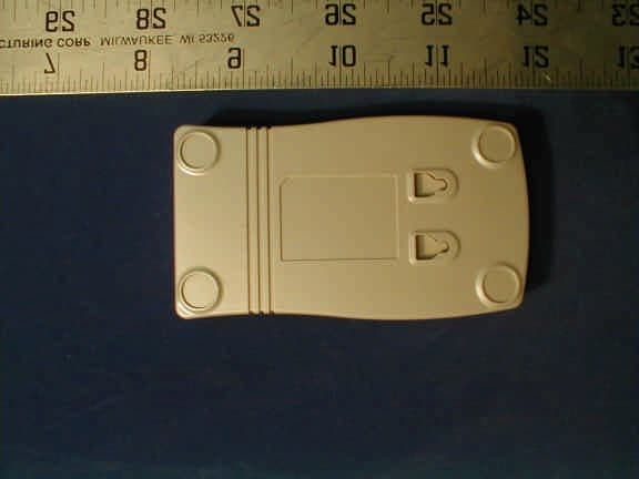
Click to zoom
Application Details
- Equipment Class
- DSS - Part 15 Spread Spectrum Transmitter
- Date of Grant
- Nov 13, 2001
- Application Purpose
- Original Equipment
- Date of Application
- Sep 06, 2001
- Frequency Range
- 2411.99000000 - 2461.99000000
- Company
- Actiontec Electronics Inc
- Country
- United States
Documents & Files
Document Text
Text extracted from the exhibit documents filed with the FCC. Open a document above to read the original.
Users Manual
802UI3 User Manuel Contents 1. Contents 2. Introduction 3. Wireless LAN Basics 4. Installation for Window 95 / 98 5. Troubleshooting 6. Technical specifications of 802UI3 2 1. FCC Warning Statement * CAUTION: To comply with FCC RF exposure requirements, a separation distance of at least 8 inches (20cm) must be maintained between the antenna of this and all persons and must not be co-located or operating in conjunction with any other antenna or transmitter. 2. Introduction Thank you for purchasing your Wireless LAN, 802UI3 PC Card. This manual will assist you with the installation procedure. The package you have received should contain the following items: • 802UI3 PC Card • User manual • Diskette containing Wireless LAN Management utility and drivers Note: if anything is missing, please contact your vendor The diskette contains the drivers and the program; this is used for managing the 802UI3 card and establishing the wireless connection with your Local Area Network. 3 3. Wireless LAN Basics Wireless LAN (Local Area Networks) systems offer a great number of advantages over a traditional, wired system. Wireless LANs (WLANs) are more flexible, easier to setup and manage and often more cost effective than their wired equivalence. Using radio frequency (RF) technology. WLANs transmit and receive data over the air, minimizing the need for wired connections. Thus, WLANs combine data connectivity with user mobility, and, through simplified configuration, enable movable LANs. With wireless LANs, users can access shared information without looking for a place to plug in and network managers can set up or augment networks without installing or moving wires. Wireless LANs offer the following productivity, convenience and cost advantages over traditional wired networks. • Mobility – Wireless LAN systems can provide LAN users with access to real-time information anywhere in their organization. This mobility supports productivity and service opportunities not possible with wired networks. • Installation Speed and Simplicity – Installing a wireless LAN system can be fast and easy and can eliminate the need to pull cable through walls and ceilings. • Installation Flexibility – wireless technology allows the network to go where wires cannot go. • Reduced Cost-of-Ownership – While the initial investment required for wireless LAN hardware might be higher than the cost of wired LAN hardware, overall installation expenses and life-cycle costs will be significantly lower. Long- term cost benefits are greatest in dynamic environments requiring frequent moves, adds, and changes. • Scalability – Wireless LAN systems can be configured in a variety of topologies to meet the needs of specific applications and installations. Configurations are easily changed and range from peer-to-peer networks suitable for a small number of users to full infrastructure networks of thousands of users that allows roaming over a broad area. 4 4. Installation for Windows 95 / 98 The following section will assist you to installing wireless LAN Adapter successfully. You will first install software (driver) and then insert the 802UI3 wireless LAN card, and finally set the network properties to accommodate resource sharing and select the type of wireless network that you wish to install. The 802UI3 can be easily be installed and used, without bothering to connect cables for keeping your computer to use network resources, as in case of wired LAN. 5 4.1 Installation Overview Here are some steps you will perform in establishing your wireless network connection: • Install the Access Point at first. AP is needed in case of Infrastructure network mode. • Install the software using the Installation Diskette. • Install the Wireless LAN Card (802UI3). • Install the network protocol(s) required to communicate on your network. Most likely you will need the TCP/IP protocol. 6 4.2 Installation Procedure of 802UI3 PC Card Note: Do not insert the USB card until you are asked to do so, failure of which may result in unsuccessful installation of your USB WLAN card. Please follow the following steps one by one in order to install the USB card successfully. 1. Power on your computer and allow Windows 95 / 98 to load fully. 2. Be sure that there is no USB adapter inserted yet. 3. Insert the given Installation Diskette and then click on the A:\disk1\setup.exe. 4. Accept the license agreement. 5. Give the path of the destination folder. To set the path of your choice click on Browser and then click Next. 6. It takes a few seconds for copying the utility files and then click on Finish to complete the installation. 7. Insert the 802UI3 card into USB slot; windows will then prompt the required driver. 8. Locate the driver path Ex. A:\ and install the driver 9. Restart the PC and Click on the Control Panel and then on PC Card. Check whether it has USB card in one of the sockets or not. If you find 802UI3 PC Card in one of the sockets, it means the card is detected properly. 10. Check for the 802UI3 Wireless USB LAN Card by right clicking on My Computer using the mouse. Select the Device manager and then Network Adapters. If you find the sign on the adapter, it shows the installation is not successful. Select the adapter and click on Remove. Restart your computer after uninstalling the driver to make the changes effective. And refer to manual. 11. Right click on the Network Neighborhood using the mouse. 12. Select Properties from the pop up menu. The network box appears and you see the three main tables: Configuration, Identification, and Access Control. 13. Click on the Configuration tab and then click on the Add button. Select Network Component Type box appears. Click on the Protocol the click the Add button. 14. Select Network Protocols box appears. From the list of manufactures, click on Microsoft. From the list of network protocols list, select NetBEUI, then click OK. 15. The NetBEUI protocol is now installed. After clicking on OK return back to Network Compone…
Text truncated - open the document above for the full version.
Block Diagram
HFA3783 QUAD IF ISL3685IR RF/IF CONV ISL3984 RFPA PLL RF LO REF IN PLL I/Q LO I ADC Q ADC RX ADC IF DAC RX DAC TX DAC Q DAC I DAC IF LO REF IN TX ADC REF_OUT TX ALC MOD DEMOD AGC CTL I/O ANT_SEL 6 1 1 1 6 6 6 6 6 REF IN 44 MHz CLOCK PHY I/O CONTROL PROCESSOR MEMORY ARBITER RADIO I/O HOST I/O WEP ENGINE CAL_EN T/R Optional Parallel FLASH USB HOST Intf Differential signals ISL3873 MAC/BBP 128Kx16 SRAM RF VCO ISL3183 IF VCO 32KHz Sleep SAW External Antenna Optional Diversity Switch External Status LEDs Serial EEPROM BLOCK DIAGRAM
External Photos
Actiontec Electronics, Inc. FCC ID: LNQ802UI3 Report # R0108151.doc FCC Part 15.247 Test Report Page 49 of 57 16 – EUT PHOTOGRAPHS 16.1 EUT-Top View Actiontec Electronics, Inc. FCC ID: LNQ802UI3 Report # R0108151.doc FCC Part 15.247 Test Report Page 50 of 57 16.2 EUT- Bottom View
ID Label/Location Info
Actiontec Electronics, Inc. FCC ID: LNQ802UI3 Report # R0108151.doc FCC Part 15.247 Test Report Page 44 of 57 14 – FCC PRODUCT LABELING AND WARNING STATEMENT 14.1 FCC ID Label Specifications: Text is black or white in color and is left justified. Labels are silk-screened and shall be “permanently affixed” at a conspicuous location on the EUT. 14.2 Proposed Label Location on EUT FCC ID: LNQ802UI 3 This device complies with Part 15 of the FCC Rules. Operation is subject to the following two conditions: (1) this device may not cause harm- ful interference, and (2) this device must accept any interference received, including interference that may cause undesired operation. 1.0" 2.1875 FCC ID: LNQ802UI3 Bottom View of EUT FCC ID Label Location
ID Label/Location Info
FCC ID Label and FCC DoC Label Location Bottom View of EUT FCC ID Label Location FCC DoC Label Location FCC ID: LNQ802UI 3 This device complies with Part 15 of the FCC Rules. Operation is subject to the following two conditions: (1) this device may not cause harm- ful interference, and (2) this device must accept any interference received, including interference that may cause undesired operation.
ID Label/Location Info
This device is in conformance with Part 15 of the FCC Rules and Regulations for Information Technology Equipment. Operation of this product is subject to the following two conditions: (1) this device may not cause harmful interference, and (2) this device must accept any interference received, including interference that may cause undesired operation. Trade Name: Actiontec Model: 802UI3 Responsible Party: Actiontec Electronics, Inc. Address: 760 North Mary Ave. Sunnyvale, CA 94086 Contact Person!Title: Ms. Alice Yeung/System/Process Analyst Telephone: (408) 752-7700 Fax: (408) 541-9005 E UTCertifi ca tio n Summary Equipment Class: FCC Class B Product Type: 802.11b Wireless LAN USB Device-lTE Report Number: ROI08151 Issuance Date: September 29, 2001 Tested by: Bay Area Compliance Laboratory Corp. Signature of Officer: ~ t:>-t1:. c../ - John Y. Chan - Engineering Manager We, the responsible party: Actiontec Electronics, Inc. - ~ . ' declare that the product ., i 802UI3 was tested to conform to the applicable FCC Rules and regulations. The method of testing was in accordance to the most accurate measurement standards possible, and that all necessary steps have been enforced to assure that all production units of the same equipment will continue to comply with the Federal Communications Commission's requirements. Signature Date Name Title
Internal Photos
Actiontec Electronics, Inc. FCC ID: LNQ802UI3 Report # R0108151.doc FCC Part 15.247 Test Report Page 51 of 57 16.3 EUT- Cover Off View Actiontec Electronics, Inc. FCC ID: LNQ802UI3 Report # R0108151.doc FCC Part 15.247 Test Report Page 52 of 57 16.4 EUT – Component View Actiontec Electronics, Inc. FCC ID: LNQ802UI3 Report # R0108151.doc FCC Part 15.247 Test Report Page 53 of 57 16.5 EUT – Solder View Actiontec Electronics, Inc. FCC ID: LNQ802UI3 Report # R0108151.doc FCC Part 15.247 Test Report Page 54 of 57 16.6 EUT – Connector View Actiontec Electronics, Inc. FCC ID: LNQ802UI3 Report # R0108151.doc FCC Part 15.247 Test Report Page 55 of 57 16.7 EUT – RF Module without Cover View
Operational Description
Description of the product Model name: 802UI Description: 802.11b Wireless LAN USB Device Form factor: Customize USB tangle The 802UI is a complete wireless high speed Network Interface (NIC) utilizing the Intersil Prism 2.5 Direct Sequence Spread Spectrum Wireless Transceiver chip set. It supports the IEEE 802.11b network specification for Direct Sequence Spread Spectrum DSSS signaling, The card is packaged in customized USB tangle. The card provides data rates of 1, 2, 5.5 and 11Mbps. The card has integrated microstrip Dual Diversity Antennas. Functional Overview The 802UI is designed to operate in the 2.4GHz ISM frequency band, channels 1 to 11, as specified by the FCC in the USA. The card will also operate on channels 12 through 14, where permitted by local regulatory authorities. The 802UI implements Direct Sequence Spread Spectrum DSSS technology providing superior noise and signal jamming immunity including less severe impact from unintentional radiators such as microwave ovens. The users can connect the 802UI in an ad-hoc peer to peer networking scheme, allowing for instant network setup in any office environment. By using an access point, the wireless LAN can be set up to allow for a greater number of users to interconnect, and to increase the coverage area. With a portal (i.e., Access Point), the wireless LAN can be easily connected into an existing wired-LAN, allowing for easy expansion of the service. Electrical rating: Voltage:+5V Transmit:280mA Receive:215mA Antenna Gain:+2.5 dBi Transmitter Power Output:15 dbm (typical) Receive Sensitivity:-83 dbm (typical)
Parts List/Tune Up Info
Q'TY R R C36.C48.C59.C62.C66-C69.C77-C79.C97.109 C23.C29.C50.C76.C80.C98.C101.C106.C116 C16.C22.C53.C60.C61.C63.C86.C92.C95.C99 C19.C35.C70.C72.C84.C89.C90.C93.C104 C1.3.4.5.7.8.10.14.15.17.18.20.21.26. 30-33.40-42.55.64.81.122.133.135.143.
Test Report
Note: This report may not be duplicated without prior written consent of Bay Area Compliance Laboratory Corporation. This report must not be used by the client to claim product endorsement by NVLAP or any agency of the U.S. Government. FCC PART 15 SUBPART C EMI MEASUREMENT AND TEST REPORT For Actiontec Electronics, Inc. 760 North Mary Avenue Sunnyvale, CA 94086 FCC ID: LNQ802UI3 September 7, 2001 This Report Concerns: Original Report Equipment Type: 802.11b Wireless LAN USB Device Test Engineer: Hien Pham Test Date: August 15, 2001 Reviewed By: John Y. Chan – Engineering Manager Prepared By: Bay Area Compliance Laboratory Corporation 230 Commercial Street, Suite 2 Sunnyvale, CA 94085 Tel: (408) 732-9162 Fax: (408) 732 9164 Actiontec Electronics, Inc. FCC ID: LNQ802UI3 Report # R0108151.doc FCC Part 15.247 Test Report Page 2 of 57 TABLE OF CONTENTS 1 - GENERAL INFORMATION.................................................................................................................................4 1.1 PRODUCT DESCRIPTION FOR EQUIPMENT UNDER TEST (EUT)..............................................................................4 1.2 OBJECTIVE............................................................................................................................................................4 1.3 RELATED SUBMITTAL(S)/GRANT(S)......................................................................................................................4 1.4 TEST METHODOLOGY............................................................................................................................................4 1.5 TEST FACILITY......................................................................................................................................................4 1.6 TEST EQUIPMENT LIST AND DETAILS....................................................................................................................5 1.7 EQUIPMENT UNDER TEST (EUT)...........................................................................................................................5 1.8 HOST SYSTEM CONFIGURATION LIST AND DETAILS.............................................................................................6 1.9 LOCAL SUPPORT EQUIPMENT LIST AND DETAILS..................................................................................................6 1.10 EXTERNAL I/O CABLING LIST AND DETAILS.......................................................................................................6 2 - SYSTEM TEST CONFIGURATION....................................................................................................................7 2.1 JUSTIFICATION......................................................................................................................................................7 2.2 EUT EXERCISE SOFTWARE...................................................................................................................................7 2.3 SPECIAL ACCESSORIES..........................................................................................................................................7 2.4 SCHEMATICS / BLOCK DIAGRAM..........................................................................................................................7 2.5 EQUIPMENT MODIFICATIONS................................................................................................................................7 2.6 CONFIGURATION OF TEST SYSTEM........................................................................................................................8 2.7 TEST SETUP BLOCK DIAGRAM..............................................................................................................................9 3 - SUMMARY OF TEST RESULTS.......................................................................................................................10 4 - CONDUCTED OUTPUT POWER MEASUREMENT.....................................................................................11 4.1 STANDARD APPLICABLE.....................................................................................................................................11 4.2 MEASUREMENT PROCEDURE...............................................................................................................................11 4.3 MEASUREMENT RESULT......................................................................................................................................11 5 – SPURIOUS EMISSION.......................................................................................................................................15 5.1 STANDARD APPLICABLE.....................................................................................................................................15 5.2 MEASUREMENT PROCEDURE...............................................................................................................................15 5.3 MEASUREMENT DATA.........................................................................................................................................15 6 – POWER DENSITY...............................................................................................................................................22 6.1 STANDARD APPLICABLE.....................................................................................................................................22 6.2 MEASUREMENT PROCEDURE...............................................................................................................................22 6.3 TEST RESULTS.....................................................................................................................................................22 7 – 6 DB BANDWIDTH.............................................................................................................................................26 7.1 STANDAR…
Text truncated - open the document above for the full version.
Test Report
Processing Gain ISL37400M 11Mbps CHANNEL 6 Processing Gain Gp = (S/N)o + Mj + Lsys Freq.Gp(S/N)oMj=J/SLsysJammerPER (MHz)(dB)(dB)(dB)(dB)(dBm)(%) 2428.5023.916.45.52.0-57.2<=8.0 2428.5523.916.45.52.0-57.2<=8.0 2428.6023.916.45.52.0-57.2<=8.0 2428.6523.816.45.42.0-57.3<=8.0 2428.7023.816.45.42.0-57.3<=8.0 2428.7524.016.45.62.0-57.1<=8.0 2428.8024.116.45.72.0-57.0<=8.0 2428.8524.116.45.72.0-57.0<=8.0 2428.9024.216.45.82.0-56.9<=8.0 2428.9524.116.45.72.0-57.0<=8.0 2429.0024.416.46.02.0-56.7<=8.0 2429.0524.316.45.92.0-56.8<=8.0 2429.1024.316.45.92.0-56.8<=8.0 2429.1524.316.45.92.0-56.8<=8.0 2429.2024.416.46.02.0-56.7<=8.0 2429.2523.716.45.32.0-57.4<=8.0 2429.3023.316.44.92.0-57.8<=8.0 2429.3523.216.44.82.0-57.9<=8.0 2429.4022.216.43.82.0-58.9<=8.0 2429.4521.316.42.92.0-59.8<=8.0 2429.5021.216.42.82.0-59.9<=8.0 2429.5521.116.42.72.0-60.0<=8.0 2429.6021.116.42.72.0-60.0<=8.0 2429.6521.016.42.62.0-60.1<=8.0 2429.7021.016.42.62.0-60.1<=8.0 2429.7520.816.42.42.0-60.3<=8.0 2429.8020.716.42.32.0-60.4<=8.0 2429.8521.116.42.72.0-60.0<=8.0 2429.9021.016.42.62.0-60.1<=8.0 2429.9521.116.42.72.0-60.0<=8.0 2430.0020.916.42.52.0-60.2<=8.0 2430.0520.916.42.52.0-60.2<=8.0 2430.1020.516.42.12.0-60.6<=8.0 2430.1519.516.41.12.0-61.6<=8.0 2430.2019.516.41.12.0-61.6<=8.0 2430.2519.016.40.62.0-62.1<=8.0 2430.3019.016.40.62.0-62.1<=8.0 2430.3518.716.40.32.0-62.4<=8.0 2430.4018.716.40.32.0-62.4<=8.0 2430.4518.516.40.12.0-62.6<=8.0 2430.5018.416.40.02.0-62.7<=8.0 2430.5518.416.40.02.0-62.7<=8.0 2430.6018.416.40.02.0-62.7<=8.0 2430.6518.116.4-0.32.0-63.0<=8.0 2430.7017.916.4-0.52.0-63.2<=8.0 2430.7517.416.4-1.02.0-63.7<=8.0 2430.8017.416.4-1.02.0-63.7<=8.0 2430.8517.116.4-1.32.0-64.0<=8.0 Prepared by: D. KalcikPage 19/7/01 Processing Gain ISL37400M 11Mbps CHANNEL 6 Processing Gain Gp = (S/N)o + Mj + Lsys Freq.Gp(S/N)oMj=J/SLsysJammerPER (MHz)(dB)(dB)(dB)(dB)(dBm)(%) 2430.9017.116.4-1.32.0-64.0<=8.0 2430.9516.916.4-1.52.0-64.2<=8.0 2431.0016.816.4-1.62.0-64.3<=8.0 2431.0516.716.4-1.72.0-64.4<=8.0 2431.1016.716.4-1.72.0-64.4<=8.0 2431.1516.316.4-2.12.0-64.8<=8.0 2431.2016.516.4-1.92.0-64.6<=8.0 2431.2516.416.4-2.02.0-64.7<=8.0 2431.3016.316.4-2.12.0-64.8<=8.0 2431.3516.316.4-2.12.0-64.8<=8.0 2431.4015.816.4-2.62.0-65.3<=8.0 2431.4515.916.4-2.52.0-65.2<=8.0 2431.5015.716.4-2.72.0-65.4<=8.0 2431.5515.516.4-2.92.0-65.6<=8.0 2431.6015.416.4-3.02.0-65.7<=8.0 2431.6515.216.4-3.22.0-65.9<=8.0 2431.7015.116.4-3.32.0-66.0<=8.0 2431.7515.016.4-3.42.0-66.1<=8.0 2431.8015.016.4-3.42.0-66.1<=8.0 2431.8514.916.4-3.52.0-66.2<=8.0 2431.9015.016.4-3.42.0-66.1<=8.0 2431.9515.116.4-3.32.0-66.0<=8.0 2432.0015.116.4-3.32.0-66.0<=8.0 2432.0515.116.4-3.32.0-66.0<=8.0 2432.1015.016.4-3.42.0-66.1<=8.0 2432.1514.816.4-3.62.0-66.3<=8.0 2432.2014.916.4-3.52.0-66.2<=8.0 2432.2514.916.4-3.52.0-66.2<=8.0 2432.3014.816.4-3.62.0-66.3<=8.0 2432.3514.616.4-3.82.0-66.5<=8.0 2432.4014.316.4-4.12.0-66.8<=8.0 2432.4514.516.4-3.92.0-66.6<=8.0 2432.5014.616.4-3.82.0-66.5<=8.0 2432.5514.516.4-3.92.0-66.6<=8.0 2432.6014.316.4-4.12.0-66.8<=8.0 2432.6514.316.4-4.12.0-66.8<=8.0 2432.7014.216.4-4.22.0-66.9<=8.0 2432.7514.116.4-4.32.0-67.0<=8.0 2432.8014.116.4-4.32.0-67.0<=8.0 2432.8513.816.4-4.62.0-67.3<=8.0 2432.9013.516.4-4.92.0-67.6<=8.0 2432.9513.716.4-4.72.0-67.4<=8.0 2433.0013.616.4-4.82.0-67.5<=8.0 2433.0513.516.4-4.92.0-67.6<=8.0 2433.1013.516.4-4.92.0-67.6<=8.0 2433.1513.516.4-4.92.0-67.6<=8.0 2433.2013.616.4-4.82.0-67.5<=8.0 2433.2513.716.4-4.72.0-67.4<=8.0 Prepared by: D. KalcikPage 29/7/01 Processing Gain ISL37400M 11Mbps CHANNEL 6 Processing Gain Gp = (S/N)o + Mj + Lsys Freq.Gp(S/N)oMj=J/SLsysJammerPER (MHz)(dB)(dB)(dB)(dB)(dBm)(%) 2433.3013.716.4-4.72.0-67.4<=8.0 2433.3513.616.4-4.82.0-67.5<=8.0 2433.4013.516.4-4.92.0-67.6<=8.0 2433.4513.416.4-5.02.0-67.7<=8.0 2433.5013.416.4-5.02.0-67.7<=8.0 2433.5513.416.4-5.02.0-67.7<=8.0 2433.6013.416.4-5.02.0-67.7<=8.0 2433.6512.916.4-5.52.0-68.2<=8.0 2433.7012.916.4-5.52.0-68.2<=8.0 2433.7512.916.4-5.52.0-68.2<=8.0 2433.8013.116.4-5.32.0-68.0<=8.0 2433.8512.916.4-5.52.0-68.2<=8.0 2433.9012.716.4-5.72.0-68.4<=8.0 2433.9513.416.4-5.02.0-67.7<=8.0 2434.0013.416.4-5.02.0-67.7<=8.0 2434.0513.416.4-5.02.0-67.7<=8.0 2434.1013.316.4-5.12.0-67.8<=8.0 2434.1513.216.4-5.22.0-67.9<=8.0 2434.2013.016.4-5.42.0-68.1<=8.0 2434.2513.016.4-5.42.0-68.1<=8.0 2434.3013.016.4-5.42.0-68.1<=8.0 2434.3513.016.4-5.42.0-68.1<=8.0 2434.4012.616.4-5.82.0-68.5<=8.0 2434.4512.816.4-5.62.0-68.3<=8.0 2434.5012.916.4-5.52.0-68.2<=8.0 2434.5512.816.4-5.62.0-68.3<=8.0 2434.6012.816.4-5.62.0-68.3<=8.0 2434.6512.716.4-5.72.0-68.4<=8.0 2434.7012.716.4-5.72.0-68.4<=8.0 2434.7512.816.4-5.62.0-68.3<=8.0 2434.8012.816.4-5.62.0-68.3<=8.0 2434.8512.316.4-6.12.0-68.8<=8.0 2434.9012.116.4-6.32.0-69.0<=8.0 2434.9512.416.4-6.02.0-68.7<=8.0 2435.0012.416.4-6.02.0-68.7<=8.0 2435.0512.416.4-6.02.0-68.7<=8.0 2435.1012.616.4-5.82.0-68.5<=8.0 2435.1512.516.4-5.92.0-68.6<=8.0 2435.2012.716.4-5.72.0-68.4<=8.0 2435.2512.716.4-5.72.0-68.4<=8.0 2435.3012.916.4-5.52.0-68.2<=8.0 2435.3512.916.4-5.52.0-68.2<=8.0 2435.4012.916.4-5.52.0-68.2<=8.0 2435.4512.616.4-5.82.0-68.5<=8.0 2435.5012.916.4-5.52.0-68.2<=8.0 2435.5512.916.4-5.52.0-68.2<=8.0 2435.6012.916.4-5.52.0-68.2<=8.0 2435.6512.816.4-5.62.0-68.3<=8.0 Prepared by: D. KalcikPage 39/7/01 Processing Gain ISL37400M 11Mbps CHANNEL 6 Processing Gain Gp = (S/N)o + Mj + Lsys Freq.Gp(S/N)oMj=J/SLsysJammerPER (MHz)(dB)(dB)(dB)(dB)(dBm)(%) 2435.7012.416.4-6.02.0-68.7<=8.0 2435.7512.516.4-5.92.0-68.6<=8.0 2435.8012.516.4-5.92.0-68.6<=8.0 2435.8512.516.4-5.92.0-68.6<=8.0 2435.9012.616.4-5.82.0-68.5<=8.0 2435.9512.816.4-5.62.0-68.3<=8.0 2436.0012.916.4-5.52.0-68.2<=8.0 2436.0513.116.4-5.32.0-68.0<=8.0 2436.1013.116.4-5.32.0-68.0<=8.0 2436.1513.116.4-5.32.0-68.0<=8.0 2436.2013.016.4-5.42.0-68.1<=8.0 2436.2513.216.4-5.22.0-67.9<=8.0 2436.3013.116.4-5.32.0-68.0<=8.0 2436.3513.016.4-5.42.0-68.1<=8.0 2436.4012.416.4-6.02.0-68.7<=8.0 2436.4513.016.4-5.42.0-68.1<=8.0 2436.5013.116.4-5.32.0-68.0<=8.0 2436.5513.016.4-5.42.0-68.1<=8.0 2436.601…
Text truncated - open the document above for the full version.
Test Report
TX (Laptop) Controller RF Gen. 20 dB Atten . Shielded Box Var. Atten. RF Wattmeter “A” RF Wattmeter “B” Spectrum Analyzer (E4407B) 16 dB Atten. (6 dB + 10 dB) 6 - 60 dB Receiver Under Test RX (Laptop) Controller Shielded Box 2-Way Combiner (6 dB) 2-Way Combiner (6 dB) 2-Way Splitter (6 dB) (optional) 2-Way Splitter (6 dB) Note 1. NOTES: 1. If Spectrum Analyzer is not used, delete optional 2-Way Splitter, connect RF Wattmeter “B” directly to previous Split- ter and change 16 dB Attenuator to 10 dB. (HP E4419B with E4412A sensitive Test Set-up - Processing Gain (Note 1. ) (HP 8648C) Trans- mitter (HP E4419B with E4412A Sensor or equiv.) (HP 11667B or equiv - typical) Sensor or equiv.) (HP 8494G & 8496G or equiv)
Test Report
1 - Conducted Output Power Measurement 1.1 Standard Applicable According to §15.247(b) (2), the maximum peak output power of the intentional radiator shall not exceed 1 Watt. 1.2 Measurement Procedure 1. Place the EUT on a bench and set it in transmitting mode. 2. Remove the antenna from the EUT and then connect a low loss RF cable from the antenna port to a power meter. 1.3 Measurement Result Peak Output PowerTest DataTest Result High Channel14.53 dBmPassed Middle Channel14.71 dBmPassed Low Channel14.36 dBmPassed 1.4 Test Equipment ManufacturerModel No.Serial No. Calibration Due Date AgilentE4419BGB402028914/8/02 AgilentE4412AUS384865294/8/02
Test Report
Processing Gain ISL37400M 11Mbps CHANNEL 6 Processing Gain Gp = (S/N)o + Mj + Lsys Freq.Gp(S/N)oMj=J/SLsysJammerPER (MHz)(dB)(dB)(dB)(dB)(dBm)(%) 2428.5023.916.45.52.0-57.2<=8.0 2428.5523.916.45.52.0-57.2<=8.0 2428.6023.916.45.52.0-57.2<=8.0 2428.6523.816.45.42.0-57.3<=8.0 2428.7023.816.45.42.0-57.3<=8.0 2428.7524.016.45.62.0-57.1<=8.0 2428.8024.116.45.72.0-57.0<=8.0 2428.8524.116.45.72.0-57.0<=8.0 2428.9024.216.45.82.0-56.9<=8.0 2428.9524.116.45.72.0-57.0<=8.0 2429.0024.416.46.02.0-56.7<=8.0 2429.0524.316.45.92.0-56.8<=8.0 2429.1024.316.45.92.0-56.8<=8.0 2429.1524.316.45.92.0-56.8<=8.0 2429.2024.416.46.02.0-56.7<=8.0 2429.2523.716.45.32.0-57.4<=8.0 2429.3023.316.44.92.0-57.8<=8.0 2429.3523.216.44.82.0-57.9<=8.0 2429.4022.216.43.82.0-58.9<=8.0 2429.4521.316.42.92.0-59.8<=8.0 2429.5021.216.42.82.0-59.9<=8.0 2429.5521.116.42.72.0-60.0<=8.0 2429.6021.116.42.72.0-60.0<=8.0 2429.6521.016.42.62.0-60.1<=8.0 2429.7021.016.42.62.0-60.1<=8.0 2429.7520.816.42.42.0-60.3<=8.0 2429.8020.716.42.32.0-60.4<=8.0 2429.8521.116.42.72.0-60.0<=8.0 2429.9021.016.42.62.0-60.1<=8.0 2429.9521.116.42.72.0-60.0<=8.0 2430.0020.916.42.52.0-60.2<=8.0 2430.0520.916.42.52.0-60.2<=8.0 2430.1020.516.42.12.0-60.6<=8.0 2430.1519.516.41.12.0-61.6<=8.0 2430.2019.516.41.12.0-61.6<=8.0 2430.2519.016.40.62.0-62.1<=8.0 2430.3019.016.40.62.0-62.1<=8.0 2430.3518.716.40.32.0-62.4<=8.0 2430.4018.716.40.32.0-62.4<=8.0 2430.4518.516.40.12.0-62.6<=8.0 2430.5018.416.40.02.0-62.7<=8.0 2430.5518.416.40.02.0-62.7<=8.0 2430.6018.416.40.02.0-62.7<=8.0 2430.6518.116.4-0.32.0-63.0<=8.0 2430.7017.916.4-0.52.0-63.2<=8.0 2430.7517.416.4-1.02.0-63.7<=8.0 2430.8017.416.4-1.02.0-63.7<=8.0 2430.8517.116.4-1.32.0-64.0<=8.0 Prepared by: D. KalcikPage 19/7/01 Processing Gain ISL37400M 11Mbps CHANNEL 6 Processing Gain Gp = (S/N)o + Mj + Lsys Freq.Gp(S/N)oMj=J/SLsysJammerPER (MHz)(dB)(dB)(dB)(dB)(dBm)(%) 2430.9017.116.4-1.32.0-64.0<=8.0 2430.9516.916.4-1.52.0-64.2<=8.0 2431.0016.816.4-1.62.0-64.3<=8.0 2431.0516.716.4-1.72.0-64.4<=8.0 2431.1016.716.4-1.72.0-64.4<=8.0 2431.1516.316.4-2.12.0-64.8<=8.0 2431.2016.516.4-1.92.0-64.6<=8.0 2431.2516.416.4-2.02.0-64.7<=8.0 2431.3016.316.4-2.12.0-64.8<=8.0 2431.3516.316.4-2.12.0-64.8<=8.0 2431.4015.816.4-2.62.0-65.3<=8.0 2431.4515.916.4-2.52.0-65.2<=8.0 2431.5015.716.4-2.72.0-65.4<=8.0 2431.5515.516.4-2.92.0-65.6<=8.0 2431.6015.416.4-3.02.0-65.7<=8.0 2431.6515.216.4-3.22.0-65.9<=8.0 2431.7015.116.4-3.32.0-66.0<=8.0 2431.7515.016.4-3.42.0-66.1<=8.0 2431.8015.016.4-3.42.0-66.1<=8.0 2431.8514.916.4-3.52.0-66.2<=8.0 2431.9015.016.4-3.42.0-66.1<=8.0 2431.9515.116.4-3.32.0-66.0<=8.0 2432.0015.116.4-3.32.0-66.0<=8.0 2432.0515.116.4-3.32.0-66.0<=8.0 2432.1015.016.4-3.42.0-66.1<=8.0 2432.1514.816.4-3.62.0-66.3<=8.0 2432.2014.916.4-3.52.0-66.2<=8.0 2432.2514.916.4-3.52.0-66.2<=8.0 2432.3014.816.4-3.62.0-66.3<=8.0 2432.3514.616.4-3.82.0-66.5<=8.0 2432.4014.316.4-4.12.0-66.8<=8.0 2432.4514.516.4-3.92.0-66.6<=8.0 2432.5014.616.4-3.82.0-66.5<=8.0 2432.5514.516.4-3.92.0-66.6<=8.0 2432.6014.316.4-4.12.0-66.8<=8.0 2432.6514.316.4-4.12.0-66.8<=8.0 2432.7014.216.4-4.22.0-66.9<=8.0 2432.7514.116.4-4.32.0-67.0<=8.0 2432.8014.116.4-4.32.0-67.0<=8.0 2432.8513.816.4-4.62.0-67.3<=8.0 2432.9013.516.4-4.92.0-67.6<=8.0 2432.9513.716.4-4.72.0-67.4<=8.0 2433.0013.616.4-4.82.0-67.5<=8.0 2433.0513.516.4-4.92.0-67.6<=8.0 2433.1013.516.4-4.92.0-67.6<=8.0 2433.1513.516.4-4.92.0-67.6<=8.0 2433.2013.616.4-4.82.0-67.5<=8.0 2433.2513.716.4-4.72.0-67.4<=8.0 Prepared by: D. KalcikPage 29/7/01 Processing Gain ISL37400M 11Mbps CHANNEL 6 Processing Gain Gp = (S/N)o + Mj + Lsys Freq.Gp(S/N)oMj=J/SLsysJammerPER (MHz)(dB)(dB)(dB)(dB)(dBm)(%) 2433.3013.716.4-4.72.0-67.4<=8.0 2433.3513.616.4-4.82.0-67.5<=8.0 2433.4013.516.4-4.92.0-67.6<=8.0 2433.4513.416.4-5.02.0-67.7<=8.0 2433.5013.416.4-5.02.0-67.7<=8.0 2433.5513.416.4-5.02.0-67.7<=8.0 2433.6013.416.4-5.02.0-67.7<=8.0 2433.6512.916.4-5.52.0-68.2<=8.0 2433.7012.916.4-5.52.0-68.2<=8.0 2433.7512.916.4-5.52.0-68.2<=8.0 2433.8013.116.4-5.32.0-68.0<=8.0 2433.8512.916.4-5.52.0-68.2<=8.0 2433.9012.716.4-5.72.0-68.4<=8.0 2433.9513.416.4-5.02.0-67.7<=8.0 2434.0013.416.4-5.02.0-67.7<=8.0 2434.0513.416.4-5.02.0-67.7<=8.0 2434.1013.316.4-5.12.0-67.8<=8.0 2434.1513.216.4-5.22.0-67.9<=8.0 2434.2013.016.4-5.42.0-68.1<=8.0 2434.2513.016.4-5.42.0-68.1<=8.0 2434.3013.016.4-5.42.0-68.1<=8.0 2434.3513.016.4-5.42.0-68.1<=8.0 2434.4012.616.4-5.82.0-68.5<=8.0 2434.4512.816.4-5.62.0-68.3<=8.0 2434.5012.916.4-5.52.0-68.2<=8.0 2434.5512.816.4-5.62.0-68.3<=8.0 2434.6012.816.4-5.62.0-68.3<=8.0 2434.6512.716.4-5.72.0-68.4<=8.0 2434.7012.716.4-5.72.0-68.4<=8.0 2434.7512.816.4-5.62.0-68.3<=8.0 2434.8012.816.4-5.62.0-68.3<=8.0 2434.8512.316.4-6.12.0-68.8<=8.0 2434.9012.116.4-6.32.0-69.0<=8.0 2434.9512.416.4-6.02.0-68.7<=8.0 2435.0012.416.4-6.02.0-68.7<=8.0…
Text truncated - open the document above for the full version.
Contact Information
Applicant
Brian Henrichs(President)
Test Firm
Bay Area Compliance LaboratoryJohn Chan
Technical Specifications
| # | Rule Parts | Frequency Range | Power Output |
|---|---|---|---|
| 1 | 15C | 2.41 GHz - 2.46 GHz | 30.00 mW |
Other Applications from Actiontec Electronics Inc

LNQWF672
Dec 26, 2025Wi-Fi 7 Outdoor Mesh AP
Equipment Class
DTS - Digital Transmission System
LNQ-WF670G
Dec 09, 2025Wi-Fi 7 Outdoor Mesh AP
Equipment Class
DTS - Digital Transmission SystemLNQ-WF815-2
Apr 14, 2024Tri-band Wi-Fi 6E Wireless AP
Equipment Class
DTS - Digital Transmission System
LNQ-WF825
Mar 24, 2024Tri-band Wi-Fi 7 Wireless AP
Equipment Class
6ID - 15E 6 GHz Low Power Indoor Access Point
LNQ-WF810G-2
Mar 23, 2024Wi-Fi 6E Mesh Extender
Equipment Class
DTS - Digital Transmission System