LNQ802UI3BUSB 802.11b Wireless LAN Adapter
Actiontec Electronics Inc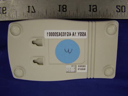
Click to zoom
Application Details
- Equipment Class
- DTS - Digital Transmission System
- Date of Grant
- Dec 25, 2002
- Application Purpose
- Original Equipment
- Date of Application
- Dec 25, 2002
- Equipment Note
- USB 802.11b Wireless LAN Adapter
- Frequency Range
- 2412.00000000 - 2462.00000000
- Company
- Actiontec Electronics Inc
- Country
- United States
Documents & Files
Document Text
Text extracted from the exhibit documents filed with the FCC. Open a document above to read the original.
Users Manual
1 Table of Contents l.Introduction2 ll. Contacting Technical Support3 lll. Connecting the Prism Wireless Adapter4 lV. Installing the Prism Wireless Adapter5 Configuring Windows 98 SE5 Configuring Windows ME8 Configuring Windows 2000 10 V.Configuring the Prism Wireless Adapter14 Vl. Configuring the AdHoc Feature16 Vll. Configuring File and Print Sharing17 Table of Contents Page ll 3 Contacting Technical Support l 2 Introduction Contacting Technical Support Thank you for purchasing the Prism Wireless Adapter. This Prism Wireless Adapter is easy to use and easy to setup. If you are tired off all those messy wires just to connect a laptop to your Home network, then take your networking to the next level with the Prism Wireless Adapter. You will be able to share files, printers and even your High- Speed Internet access, all without wires. Package Contents Make sure the following items came in this package: Prism Wireless Adapter USB Cable Prism Wireless Adapter Installation CD-ROM This User’s Manual and Quick Start Installation Guide Minimum System Requirements One Pentium class computer, 200 Mhz or higher (preferably 300 Mhz or above) Microsoft Windows 98 Second Edition (SE), Microsoft ME, Microsoft 2000 installed Introduction lV 5 Installing the Prism Wireless Adapter lll 4 Connecting the Prism Wireless Adapter 1.It will not affect the installation process if your computer is on or off. However, if your computer is off then after you have connected the Prism Wireless Adapter, please be sure to turn on your computer. 2.Insert the Prism Wireless Adapter into the appropriate USB slot on either the front or the back of your PC. Connecting the Prism Wireless Adapter For Windows 98 1.After you have installed the Prism Wireless Adapter your computer will display an “Add New Hardware Wizard” screen. Click Next. Installing the Prism Wireless Adapter 2.In the next screen, select the option Search for the best driver for your deviceand then click the Nextbutton. lV 7 Installing the Prism Wireless Adapter lV 6 Installing the Prism Wireless Adapter 3.Please insert the Prism Wireless Adapter Installation CD into your CD-ROM drive. Select CD-ROM Driveand then click Next. 4.Your computer will locate the correct drivers named “AEIWLNIC.inf ”. Click Next to install the drivers. 5.The Prism Wireless Adapter’s properties screen will appear. (Note: The “SSID” must be the same as the “ESSID” on your Home Gateway or Access Point.) Click OKto complete the installation process. 6.The installation is now complete. Please click Finish. lV 9 Installing the Prism Wireless Adapter lV 8 Installing the Prism Wireless Adapter 7.It will be necessary for you to shut down your computer. Please click OKto restart your computer. If this screen does not appear please restart your computer manu- ally. Windows ME 1.After you have installed the Prism Wireless Adapter your computer will display an “Add New Hardware Wizard” screen. Click Automatic search for a better driver (Recommended). Then click the Next button. 2.The Prism Wireless Adapter’s properties screen will appear. (Note: The “SSID” must be the same as the “ESSID” on your Home Gateway or Access Point.) Click OKto complete the installation process. 3.The installation is now complete. Please click Finish. lV 11 Installing the Prism Wireless Adapter For Windows 2000 1.After you have installed the Prism Wireless Adapter your computer will display the “Found New Hardware Wizard” screen. Click Next. 2.In the next screen, select the option Search for the best driver for your deviceand then click the Nextbutton. lV 10 Installing the Prism Wireless Adapter 4.It will be necessary for you to shut down your computer. Please click OKto restart your computer. If this screen does not appear please restart your computer manu- ally. 3.Please insert the Prism Wireless AdapterInstallation CD into your CD-ROM drive. Select CD-ROM Driveand then click Next. lV 13 Installing the Prism Wireless Adapter lV 12 Installing the Prism Wireless Adapter 4.Your computer will locate the correct drivers named “AEIWLNIC.inf ”. Click Next to install the drivers. 5.The “Wireless LAN Configuration Utility” screen will appear. (Note: The “SSID” must be the same as the “ESSID” on your Home Gateway or Access Point.) Click OKto continue the installation process. 6.If you have configured any Encryption capabilities in your Home Gateway or Access Point then complete the following screen accordingly. Otherwise, please click Finishto complete the installation process. V 15 Configuring the Prism Wireless Adapter V 14 Configuring the Prism Wireless Adapter After you have installed the software for the Prism Wireless Adapteran, Icon will appear in your Task Bar on the lower right hand side on your Desktop. You will not be automatically connect- ed to your Home Gateway or Access Point. Follow these steps to configure your Prism Wireless Adapter. Configuring the Prism Wireless Adapter Prism Wireless Adapter Status Icon 3.After you have entered the appropriate SSID value click Applyand then click OK. Your Prism Wireless Adapter will now be able to connect to your Home Gateway or Access Point. If your Home Gateway or Access Point is connected to a DSL or Cable modem then test your wireless connection. You can do this by opening your Internet Browser and then surf the web. Note:There are two colored bars on either side of the Prism Wireless AdapterIcon. When they are Green it means that your wireless connection is strong or good. When they are Yellowit means that your wireless connection is fair. When they are Redit means that your wireless connection is poor or weak. When the bars are Yellow or Red you may experience slower connection speeds then when they are Green. Encryption (WEP) You can use Encryption to add a level of security to your Prism Wireless Adapter net- work. This is not a required feature. If you are using a Home Gateway or Access Point you must be sure to use the same Encryption (WEP) keys for your Prism Wir…
Text truncated - open the document above for the full version.
External Photos
EXHIBIT C - EUT EXTERNAL PHOTOGRAPHS EUT - Front View EUT - Rear View EUT – Top View EUT – Bottom View
Internal Photos
EXHIBIT C - EUT INTERNAL PHOTOGRAPHS EUT - Component View EUT – Component without Shield View EUT – Solder View
Test Report
Note: This test report is specially limited to the above client company and product model only. It may not be duplicated without prior written consent of Bay Area Compliance Laboratory Corporation. This report must not be used by the client to claim product endorsement by NVLAP or any agency of the U.S. Government. FCC PART 15 SUBPART C EMI MEASUREMENT AND TEST REPORT For Actiontec Electronics, Inc. 760 N. Mary Ave. Sunnyvale, CA 94086 FCC ID: LNQ802UI3B December 9, 2002 This Report Concerns: Original Report Equipment Type: USB 802.11b Wireless LAN Adapter Test Engineer:Jeff Lee Report No.:R0211151 Test Date:November 28, 2002 Reviewed By:Hans Mellberg Prepared By:Bay Area Compliance Laboratory Corporation (BACL) 230 Commercial Street Sunnyvale, CA 94085 Tel: (408) 732-9162 Fax: (408) 732 9164 Actiontec Electronics, Inc. FCC ID: LNQ802UI3B Report # R0211151RptPage 2 of 36 FCC Part 15.247 Test Report TABLE OF CONTENTS 1 - GENERAL INFORMATION.................................................................................................................................................4 1.1PRODUCT DESCRIPTION FOR EQUIPMENT UNDER TEST (EUT)......................................................................................4 1.2 OBJECTIVE................................................................................................................................................................................4 1.3 RELATED SUBMITTAL(S)/GRANT(S)......................................................................................................................................4 1.4 TEST METHODOLOGY.............................................................................................................................................................4 1.5 TEST FACILITY.........................................................................................................................................................................4 1.6 TEST EQUIPMENT LIST............................................................................................................................................................5 1.7 HOST SYSTEM CONFIGURATION LIST AND DETAILS..........................................................................................................5 1.8 SUPPORT EQUIPMENT LIST AND DETAILS............................................................................................................................5 1.9 EXTERNAL I/O CABLING LIST AND DETAILS......................................................................................................................6 2 - SYSTEM TEST CONFIGURATION..................................................................................................................................7 2.1 JUSTIFICATION.........................................................................................................................................................................7 2.2 EUT EXERCISE SOFTWARE....................................................................................................................................................7 2.3 SPECIAL ACCESSORIES............................................................................................................................................................7 2.4 SCHEMATICS / BLOCK DIAGRAM..........................................................................................................................................7 2.5 EQUIPMENT MODIFICATIONS.................................................................................................................................................7 2.6 CONFIGURATION OF TEST SYSTEM.......................................................................................................................................8 2.7 TEST SETUP BLOCK DIAGRAM..............................................................................................................................................8 3 - SUMMARY OF TEST RESULTS........................................................................................................................................9 4 - CONDUCTED OUTPUT POWER MEASUREMENT................................................................................................10 4.1 STANDARD APPLICABLE.......................................................................................................................................................10 4.2 MEASUREMENT PROCEDURE...............................................................................................................................................10 4.3 TEST EQUIPMENT..................................................................................................................................................................10 4.4 MEASUREMENT RESULT.......................................................................................................................................................10 5 – 6 DB BANDWIDTH...............................................................................................................................................................14 5.1 STANDARD APPLICABLE.......................................................................................................................................................14 5.2 MEASUREMENT PROCEDURE...............................................................................................................................................14 5.3 MEASUREMENT RESULT.......................................................................................................................................................14 6 - SPURIOUS EMISSION.........................................................................................................................................................17 6.1 STANDARD APPLICABLE.....................................................................…
Text truncated - open the document above for the full version.
Test Setup Photos
EXHIBIT B - TEST SETUP PHOTOGRAPHS Conducted Emission - Front View Conducted Emission - Rear View Radiated Emission - Front View Radiated Emission - Rear View
Contact Information
Applicant
Brian Henrichs(President)
Test Firm
Bay Area Compliance LaboratoryJohn Chan
Technical Specifications
| # | Rule Parts | Frequency Range | Power Output |
|---|---|---|---|
| 1 | 15C | 2.41 GHz - 2.46 GHz | 41.40 mW |
Other Applications from Actiontec Electronics Inc

LNQWF672
Dec 26, 2025Wi-Fi 7 Outdoor Mesh AP
Equipment Class
DTS - Digital Transmission System
LNQ-WF670G
Dec 09, 2025Wi-Fi 7 Outdoor Mesh AP
Equipment Class
DTS - Digital Transmission SystemLNQ-WF815-2
Apr 14, 2024Tri-band Wi-Fi 6E Wireless AP
Equipment Class
DTS - Digital Transmission System
LNQ-WF825
Mar 24, 2024Tri-band Wi-Fi 7 Wireless AP
Equipment Class
6ID - 15E 6 GHz Low Power Indoor Access Point
LNQ-WF810G-2
Mar 23, 2024Wi-Fi 6E Mesh Extender
Equipment Class
DTS - Digital Transmission System