LNQBTM200USB Bluetooth Wireless Module
Actiontec Electronics Inc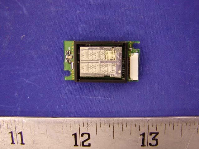
Click to zoom
Application Details
- Equipment Class
- DSS - Part 15 Spread Spectrum Transmitter
- Date of Grant
- Mar 12, 2003
- Application Purpose
- Original Equipment
- Date of Application
- Mar 12, 2003
- Equipment Note
- USB Bluetooth Wireless Module
- Frequency Range
- 2402.00000000 - 2480.00000000
- Company
- Actiontec Electronics Inc
- Country
- United States
Documents & Files
Document Text
Text extracted from the exhibit documents filed with the FCC. Open a document above to read the original.
Users Manual
Bluetooth BTM200 OEM Installation Manual 2 Contents 1. Contents 2. Introduction 3. Bluetooth Basics 4. Installation Overview 5. Troubleshooting 6. Bluetooth Technical Specifications 3 2. Introduction Thank you for purchasing Actiontec USB Bluetooth Wireless Module. This manual will assist you with the installation procedure. The package you have received should contain the following items: • USB Bluetooth Wireless Module • OEM Installation Manual • Wireless LAN Management utility and driver software. Note: if anything is missing, please contact your vendor The diskette contains drivers and utility software; this is used for managing the Bluetooth and needed components. The Bluetooth is designed to provide Bluetooth wireless function on a customized form factor. The Bluetooth wireless function is based on CSR BlueCore-02 chip, which is fully compliant with Bluetooth version 1.1 standard. It has an USB interface to the host. 4 3. Wireless Bluetooth Basics Wireless Bluetooth systems offer a great number of advantages over a traditional, wired system. Wireless Bluetooth are more flexible, easier to setup and manage and often more cost effective than their wired equivalence. Using radio frequency (RF) technology. Bluetooth transmits and receives data over the air, minimizing the need for wired connections. Thus, Bluetooth combines data connectivity with user mobility, and, through simplified configuration, enable movable LANs. With wireless Bluetooth, users can access shared information without looking for a place to plug in and network managers can set up or augment networks without installing or moving wires. Wireless Bluetooth offers the following productivity, convenience and cost advantages over traditional wired networks. • Mobility – Wireless Bluetooth systems can provide LAN users with access to real-time information anywhere in their organization. This mobility supports productivity and service opportunities not possible with wired networks. • Installation Speed and Simplicity – Installing a wireless Bluetooth system can be fast and easy and can eliminate the need to pull cable through walls and ceilings. • Installation Flexibility – wireless technology allows the network to go where wires cannot go. • Reduced Cost-of-Ownership – While the initial investment required for wireless Bluetooth hardware might be higher than the cost of wired LAN hardware, overall installation expenses and life-cycle costs will be significantly lower. Long- term cost benefits are greatest in dynamic environments requiring frequent moves, adds, and changes. • Scalability – Wireless Bluetooth systems can be configured in a variety of topologies to meet the needs of specific applications and installations. Configurations are easily changed and range from peer-to-peer networks suitable for a small number of users to full infrastructure networks of thousands of users that allow roaming over a broad area. 5 4. OEM Installation Procedures of Bluetooth Please follow the below steps one by one to install the utility and driver software successfully. 1. Take JST connector to plug into the 8-pin connector located on the same side of the PCB as antenna. 2. Power on your PC and allow Windows to load fully. 3. Windows first time detects the USB device (Bluetooth by HP); click “cancel”. 4. Insert the given Installation diskette and then double click the setup.exe file to run setup. 5. Click “Next” in the welcome window. 6. Click the option for to accept the terms in the license agreement, then click “Next”. 7. Click “Next” to install to this folder, or click “Change” to install to a different folder. 8. Click “Install” to begin installation of WIDCOMM Bluetooth Software. 9. Click “OK” to disable unsigned deriver warnings. 10. Click “Finish” to complete the installation. 11. Recommended to select “Yes” to restart your PC to make the changes effective when screen message pop up. 12. If the software dose not fix device’s driver, manually install driver from specific location when the notice pop up. 13. Select “Advance” and click next to continue; browse the driver location C:\Program Files\WIDCOMM\Bluetooth Software\bin Then, finish the software installing. 14. Double click the icon of My Bluetooth Places, and place some options of features on the computer before to begin using Bluetooth, then click “Next”. 15. Select a name for your computer and indicate what type of computer it is. 16. Click “Next” to configure the Bluetooth services; otherwise, click “Skip”. Go to step 18. 17. To enable a service, place a check in the box next to the service name. To display the properties panel for a service, click “Configure”. 18. If you have another Bluetooth device and you want to configure the way this computer will use its services, click “Next”. Otherwise click “Skip”. 19. Select a device that must be in discoverable mode for your computer to find them, then click “Next”. 20. To begin the paring process, enter the PIN code and click “Initiate Paring”. Otherwise click “Skip”. 21. Select available service through the selected Bluetooth device, and click “Next”. 22. Repeat step 16, or click “Skip”. 23. Click “Finish” for the completion of basic Bluetooth configuration. 24. Check “Entire Bluetooth Neighborhood” to search any other available Bluetooth device for communication. Please note that it is OEM's responsibility to put the FCC regulatory label containing the words "contains Tx FCC ID:LNQBTM200". 6 5. Troubleshooting USB Bluetooth Wireless Module If you still encounter some problems while installing the Bluetooth utility and driver software or you want to confirm whether your software is installed properly or not, we have listed the procedure for checking the various components after you have installed the software. In section below, we have listed the various problems that you may encounter during the installation and have also listed the possible solution. Procedure to check the various properties of card after installation un…
Text truncated - open the document above for the full version.
Cover Letter(s)
February 12, 2003 The 2.4GHz Frequency Hopping USB Wireless LAN Module, FCC ID: LNQBTM200 is seeking FCC Authorization as a modular transmitter. The EUT meets the requirements for modular approval as detailed in FCC public Notice DA00-1407. Compliance to each of the requirements is described below: Questions are: 1. “The modular transmitter must have its own RF shielding.” - The radio portion of the wireless LAN module has its own RF shielding. The shielding is installed at the factory. Please see Exhibit C for photographs of the shielding, found in file R0302101Ext. 2. “The modular transmitter must have buffered modulation/data inputs.” - The EUT has buffered data inputs to insure compliance with Part 15 requirements under condition of excessive data rates or over – modulation. Please see Appendix 1for schematics of the module, found in file R0302101Sch. 3. “The modular transmitter must have its own power supply regulation.” - The EUT uses USB host power. It insures compliance with port 15 supplying the module from the host unit. Please see Appendix 1 for schematics of the module, found in file R0302101Sch. 4. “The modular transmitter must comply with the antenna requirements of section 15.203 and 15.204(c).” - The EUT meets the FCC antenna requirements. Please see Appendix 2 for x1726 circuit description, found in file R0302101Op; Exhibit C for photographs of the antennas, found in file R0302101Ext/E0302101Int, and Appendix 3 for antenna connection method, found in file R0302101AntSpc. 5. “The modular transmitter must be tested in a stand-alone configuration.” - The EUT was tested in a stand-alone configuration. Please see Appendix 2 for x1726 circuit description, found in file R0302101Op, and Exhibit B for the testing setup photos, found in file R0302101Sup. - 1/2 - 6. “The modular transmitter must be labeled with its own FCC ID number.” - The EUT is labeled with its own FCC ID number. Please see Exhibit A for a drawing of the label and its location on the device, found in file R0302101Lbl. Since the FCC ID number will not be visible when the module is installed inside a host computer, there’re instructions given to the OEM on how to apply the exterior label. 7. “The modular transmitter must comply with any specific rule or operating requirements applicable to the transmitter and the manufacture must provide adequate instruction along with the module to explain any such requirements.” - The EUT is compliant with all applicable FCC rules. Please see test report for the detailed RF Exposure, found in file R0302101Rpt. 8. “The modular transmitter must comply with any applicable RF exposure requirements.” – The EUT fully complies with RF exposure requirements. Please see test report for the detailed RF Exposure, found in file R0302101Rpt. - 2/2 -
External Photos
EXHIBIT C - EUT EXTERNAL PHOTOGRAPHS EUT – Front View EUT – Rear View R0302101Ext
ID Label/Location Info
EXHIBIT A - FCC ID LABEL INFORMATION Proposed FCC ID Label 2.1875”L x 1.0”W Proposed Label Location on EUT Solder Side of EUT/FCC ID Label R0302101Lbl FCC ID: LNQBTM200 This device complies with Part 15 of the FCC Rules. Operation is subject to the following two conditions: (1) this device may not cause harmful interference, and (2) this device must accept any interference received,
Internal Photos
EXHIBIT C - EUT INTERNAL PHOTOGRAPHS EUT – Front View EUT – Component View R0302101Int
Test Report
Note: This test report is specially limited to the above client company and product model only. It may not be duplicated without prior written consent of Bay Area Compliance Laboratory Corporation. This report must not be used by the client to claim product endorsement by NVLAP or any agency of the U.S. Government. FCC PART 15 SUBPART C EMI MEASUREMENT AND TEST REPORT For Actiontec Electronics, Inc. 760 N. Mary Ave. Sunnyvale, CA 94086 FCC ID: LNQBTM200 February 26, 2003 This Report Concerns: Original Report Equipment Type: USB Bluetooth Wireless Module Test Engineer: Jerry Wang Report No.: R0302101 Test Date: February 12, 2003 Reviewed By: Hans Mellberg Prepared By: Bay Area Compliance Laboratory Corporation (BACL) 230 Commercial Street Sunnyvale, CA 94085 Tel: (408) 732-9162 Fax: (408) 732 9164 Actiontec Electronics, Inc. FCC ID: LNQBTM200 Report # R0302101Rpt.doc Page 2 of 46 FCC Part 15.247 Test Report TABLE OF CONTENTS 1 - GENERAL INFORMATION..................................................................................................................................4 1.1 PRODUCT DESCRIPTION FOR EQUIPMENT UNDER TEST (EUT) ..............................................................................4 1.2 OBJECTIVE.............................................................................................................................................................4 1.3 RELATED SUBMITTAL(S)/GRANT(S).......................................................................................................................4 1.4 TEST METHODOLOGY............................................................................................................................................4 1.5 TEST FACILITY.......................................................................................................................................................5 1.6 TEST EQUIPMENT LIST...........................................................................................................................................5 1.7 HOST SYSTEM CONFIGURATION LIST AND DETAILS..............................................................................................6 1.8 EXTERNAL I/O CABLING LIST AND DETAILS.........................................................................................................6 2 - SYSTEM TEST CONFIGURATION.....................................................................................................................7 2.1 JUSTIFICATION.......................................................................................................................................................7 2.2 EUT EXERCISE SOFTWARE....................................................................................................................................7 2.3 SPECIAL ACCESSORIES...........................................................................................................................................7 2.4 SCHEMATICS / BLOCK DIAGRAM...........................................................................................................................7 2.5 EQUIPMENT MODIFICATIONS.................................................................................................................................7 2.6 CONFIGURATION OF TEST SYSTEM.........................................................................................................................8 2.7 TEST SETUP BLOCK DIAGRAM...............................................................................................................................8 3 - SUMMARY OF TEST RESULTS..........................................................................................................................9 4 - MAXIMUM PEAK OUTPUT POWER...............................................................................................................10 4.1 STANDARD APPLICABLE......................................................................................................................................10 4.2 MEASUREMENT PROCEDURE................................................................................................................................10 4.3 TEST EQUIPMENT.................................................................................................................................................10 4.4 MEASUREMENT RESULT......................................................................................................................................10 4.5 PLOTS OF MAXIMUM PEAK OUTPUT POWER........................................................................................................10 5 - CHANNEL BANDWIDTH ...................................................................................................................................14 5.1 STANDARD APPLICABLE......................................................................................................................................14 5.2 MEASUREMENT PROCEDURE................................................................................................................................14 5.3 MEASUREMENT RESULT......................................................................................................................................14 5.4 PLOT OF CHANNEL BANDWIDTH..........................................................................................................................14 6 - NUMBER OF HOPPING FREQUENCY USED ................................................................................................18 6.1 STANDARD APPLICABLE......................................................................................................................................18 6.2 MEASUREMENT PROCEDURE................................................................................................................................18 6.3 MEASUREMENT PROCEDURE....................................................…
Text truncated - open the document above for the full version.
Test Setup Photos
EXHIBIT B - TEST SETUP PHOTOGRAPHS Conducted Emission - Front View Conducted Emission - Rear View R0302101Sup Radiated Emission - Front View Radiated Emission - Rear View R0302101Sup Radiated Emission - Rear View 2 R0302101Sup.
Contact Information
Applicant
Brian Henrichs(President)
Test Firm
Bay Area Compliance LaboratoryJohn Chan
Technical Specifications
| # | Rule Parts | Frequency Range | Power Output |
|---|---|---|---|
| 1 | 15C | 2.40 GHz - 2.48 GHz | 1.78 mW |
Other Applications from Actiontec Electronics Inc

LNQWF672
Dec 26, 2025Wi-Fi 7 Outdoor Mesh AP
Equipment Class
DTS - Digital Transmission System
LNQ-WF670G
Dec 09, 2025Wi-Fi 7 Outdoor Mesh AP
Equipment Class
DTS - Digital Transmission SystemLNQ-WF815-2
Apr 14, 2024Tri-band Wi-Fi 6E Wireless AP
Equipment Class
DTS - Digital Transmission System
LNQ-WF825
Mar 24, 2024Tri-band Wi-Fi 7 Wireless AP
Equipment Class
6ID - 15E 6 GHz Low Power Indoor Access Point
LNQ-WF810G-2
Mar 23, 2024Wi-Fi 6E Mesh Extender
Equipment Class
DTS - Digital Transmission System