LNQBTM200BUSB Bluetooth Adapter
Actiontec Electronics Inc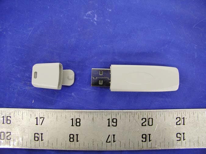
Click to zoom
Application Details
- Equipment Class
- DSS - Part 15 Spread Spectrum Transmitter
- Date of Grant
- Jul 01, 2003
- Application Purpose
- Original Equipment
- Date of Application
- Jul 01, 2003
- Equipment Note
- USB Bluetooth Adapter
- Frequency Range
- 2402.00000000 - 2480.00000000
- Company
- Actiontec Electronics Inc
- Country
- United States
Documents & Files
Document Text
Text extracted from the exhibit documents filed with the FCC. Open a document above to read the original.
Users Manual
1 Introduction Thank you for purchasing the Actiontec USBWireless Bluetooth Adapter. Now you can truly enjoy the freedom of wireless connectivity with Actiontec's USBWireless Bluetooth Adapter. Simply plug this tiny adapter into any USB port on your computer, and you can exchange information between it and any other Bluetooth enabled device. Imagine sharing your internet connection by simply requesting it from any computer, or PDA. Connect on the go by using your cell phone as a high speed modem or simply print to any bluetooth enabled printer, The Actiontec USBWireless Bluetooth Adapter lets you enjoy the freedom of tru mobility whether you're at the office or on the move, What is Bluetooth? Bluetooth is a worldwide standard for digital wireless communication and data exchange between two devices. Bluetooth compliant devices exchange data by establishing a relationship with each other, the first device acting as a client, requests a connection, while the second device acting as a server accepts or rejects tht request. Bluetooth devices can behave as client and server; however there are many Bluetooth devices that can only behave as a client. Client Bluetooth devices can only request a connection from other Bluetooth-enabled devices such as a computer, modem, printer, cell phone or PDA. Server devices are usually more complex that client devices since these are the one that determine what services can be used by others. Server devices are aware of the number client device requests since they are constantly monitoring activity to determine whether the accept or reject a request. Package Contents ßActiontec USBWireless Bluetooth Adapter ßInstallation CDs ßQuick start guide ßWarranty and registration card 1 2 Actiontec USBWireless Bluetooth Adapter Minimum System Requirements ßMicrosoft Windows 98SE, ME, 2000, XP ßAvailable USBPort ßPentium 90 or faster ß16MB or RAM ßTCP/IP installed Technical Support Actiontec Electronics prides itself on making high-quality, durable, high-performance products. If you need assistance, the Actiontec Technical Support Department is available every day from 6 A.M. to 11 P.M. (MST) to provide professional support. Actiontec Electronics, Inc. 760 N. Mary Avenue Sunnyvale, CA 94085 Technical Support Phone: (888) 436-0657 E-mail: [email protected] Internet: www.actiontec.com/support Installing the USBWireless Bluetooth Adapter The instructions that follow provide a visual guide to setting up the Actiontec USBWireless Bluetooth Adapter. It is recommended the user follow these instructions prior to attempting any other procedures. This manual will guide through hardware and software installation and configuration. 2.1 Bluetooth Software Installation + Note:Bluetooth software must be intalled prior to plugging the USB Wireless Bluetooth Adapter to a USB port. If the USB Wireless Bluetooth Adapter is connected to your computer, please remove it and cancel any hardware wizards that may show up. Restart your computer and proceed with step 1. 1.Insert the Actiontec USB Wireless Bluetooth Adapter Driver CD into your CD-ROM Drive. The Installation Wizard will run and the following screen will appear, when ready click Next to continue. 3 2 4 Actiontec USBWireless Bluetooth Adapter 2.Wait until the License Agreement screen appears, read the License Agreement carefully. Select “Iaccept the terms in the license agreement” and click Next to continue. + Note:If you are not in agreement with the license agreement terms, Select “Ido not accept the terms in the license agreement” and clcik Nextto stop the installation process. 3.When the following screen appears, click Installto continue. 4.The following screen appears, click OKto continue. 5 Chapter 2 Installing the Bluetooth Adapter 5.During Installation, the following screen appears, click CANCELto continue. 7.When the following screen appears, click Finishto continue. 2.2 Bluetooth Hardware Installation 1.Plug the Actiontec USB Wireless Bluetooth Adapter into any available USB port on your computer as shown below. Insert Picture of USBWireless Bluetooth Adapter plugging into notebook or PC 6 Actiontec USBWireless Bluetooth Adapter 2.The “Found New Hardware Wizard” will run and the following screen will appear, make sure “Install the software automatically (Reccommended)” is selected. When ready click Next to continue. 3.The “Found New Hardware Wizard” will automatically search for the appro- priate drivers, once found it will request whether you would like to proceed or not. In order to proceed with the installation, when the following window appears, click on C ontinue Anyway. 7 Chapter 2 Installing the Bluetooth Adapter 4.The following screen appears, Click on Finishto complete the installation process. 5.The Bluetooth Icon will appear in the taskbar. Congratulations!, you have successfully installed the Actiontec USBWireless Bluetooth Adapter. 8 Bluetooth Software The Actiontec USBWireless Bluetooth Adapter ships with the management software required to fully integrate your Bluetooth-enabled computer with other bluetooh-enabled devices. There ar many methods by which relationships between Bluetooth-enabled devices can be established. 3.1 The Bluetooth Tray The Bluetooth tray resides in the Windows system tray, which is normally located in the lower-right corner of the screen. The Bluetooth tray provides fast access to most Bluetooth operations. The Bluetooth tray provides the following options: •Access My Bluetooth Places Double-click the Bluetooth icon, or right-click the Bluetooth icon and then select Explore My Bluetooth Places. • Access the Bluetooth Setup Wizard. This wizard will help you: • Configure how this computer accesses a service on another Bluetooth enabled devices. • Locate remote Bluetooth devices • Configure the way that this computer provides services to remote Bluetooth-enabled devices. • Set the name and type of this Bluetooth device, e.g., “John's PC” and “Desktop.” • Access the Bluetooth Configura…
Text truncated - open the document above for the full version.
External Photos
EXHIBIT C - EUT EXTERNAL PHOTOGRAPHS EUT – Chassis Front View EUT – Chassis Rear View
ID Label/Location Info
EXHIBIT A - FCC ID LABEL INFORMATION Proposed FCC ID Label 2.1875”L x 1.0”W Proposed Label Location on EUT Rear View of EUT/FCC ID Label FCC ID: LNQBTM200B This device complies with Part 15 of the FCC Rules. Operation is subject to the following two conditions: (1) this device may not cause harmful interference, and (2) this device must accept any interference received,
Internal Photos
EXHIBIT C - EUT INTERNAL PHOTOGRAPHS EUT – Cover Off Component View EUT – Cover Off Solder View RF Module – Component View RF Module – Bottom With Antenna View
Operational Description
Basic Operation Theory of Actiontec Bluetooth BTM200B Actiontec Electronics, Inc. 6/5/2003 V18 VCC_BT[3.3V]VCC_USB[5V] LED 1.8V LDO 3 1 24 5 CE VIN GNDBYP VOUT BALUN 1 23 4 5 6 UNBAL DC_F BAL BAL GND NC BPF 4 21 3 GND OUTIN GND 16MHZ CRYSTAL 12 34 3.3V LDO 3 1 24 5 CE VIN GNDBYP VOUT ANTENNA 1 8M BIT FLASH CSR BC-02 USB HOST CONNECTOR System Block Diagram Actiontec BTM200B is using BlueCore 2 (CSR BC-02) of Cambridge Silicon Radio as its main chip set. It is actually a combination of 2.4GHz ISM Band Tranceiver, Baseband & Logic plus Microcontroller. The module is fully compliant with Bluetooth Standard v.1.1. Basically it is FHSS (Frequency Hopping Spread Spectrum), which is 1600 hops/s, and the modulation of RF carriers is GFSK (Gaussian Frequency Shift Keying). Transmitter Path Refer to the Device Diagram and System Block Diagram. The transmitter output power is Bluetooth Class 2, or 4dBm maximum. The module interface format is USB (Universal Serial Bus). So the BTM200B module acts as a USB peripheral, responding to requests from a master host controller such as a PC. The having processed data coming from Baseband & Logic is fed to a D/A converter, then to a digital baseband transmit filter which provides the required spectral shaping. A multiplier plays a role of direct I/Q modulator to fulfill GFSK modulation with a controlled modulation index. The chip built-in PA has a maximum output power of +4dBm allowing transmitter to meet Bluetooth Class 2 without using external PA. The RF Synthesizer has been integrated into the chip set so that there is no need to add external components such as VCO (Voltage Controlled Oscillator), tuning diode but a simple RC loop filter. Frequency Hopping function is done through RF Synthesizer too. The PA output from the chip set is differential to reduce common mode noise. An external Balun transformer converts the differential to single ended signal which then passes through a BPF (Band Pass Filter) blocking all unwanted out of band emissions. Receiver Path The receiver path is basically a reverse process to transmitter. The off air signal passes through BPF and Balun to a chip built-in LNA (Low Noise Amplifier). A receive multiplier down converts the channel signal to a near-zero IF (Intermediate Frequency) which is then filtered out and fed to a FSK discriminator. The data stream coming out from the discriminator goes to the Baseband & Logic for further processing. This architecture allows the filters to be integrated into the chip set. Sufficient out of band blocking specification at LNA input allows the radio to be used in close proximity to GSM Mobile Communications and WCDMA cellular phone transmitters without being interfered. The excellent performance in the noise presence of Actiontec BTM200B allows the system to exceed the Bluetooth requirements for co-channel and adjacent channel rejection. A RSSI (Received Signal Strength Indication) line is internally hooked up to an A/D converter. This constructs a part of AGC loop for the receiver. The rest of the circuitry is within the Baseband & Logic and comes back to the gain control of the LNA. Microcontroller, Baseband & Logic The microcontroller, interrupt controller and event timer run the Bluetooth software stack, which is loaded in a 8Mbit flash, and control the radio and host interfaces. Two terminals of the Programmable I/O ports are currently used for LED indication. The Memory Management Unit (MMU) provides a number of dynamically allocated ring buffers that hold the data which is in transit between the host and the air or vice versa. The dynamic allocation of memory ensures efficient use of the available RAM and is performed by a hardware MMU to minimize the overheads on the processor during data transfer. The Physical Layer Hardware Engine DSP is dedicated to perform: Forward error correction, Header error control, Cyclic redundancy check, Encryption, Data whitening, Access code correlation and Audio transcoding. During radio transmission, Burst Mode Controller (BMC) constructs a packet from header information previously loaded into memory-mapped registers by the software and payload data/voice taken from the appropriate ring buffer in RAM. During radio reception, the BMC stores the packet header in memory-mapped registers and the payload data in the appropriate ring buffer in RAM. This architecture minimizes the intervention required by the processor during transmission and reception.
RF Exposure Info
RF EXPOSURE According to §15.247(b)(4) and §1.1307(b)(1), systems operating under the provisions of this section shall be operated in a manner that ensures that the public is not exposed to radio frequency energy level in excess of the Commission’s guidelines. According to §1.1310 and §2.1093 RF exposure is calculated. Limits for Maximum Permissive Exposure (MPE) Frequency Range (MHz) Electric Field Strength (V/m) Magnetic Field Strength (A/m) Power Density (mW/cm 2 ) Averaging Time (minute) Limits for General Population/Uncontrolled Exposure 0.3-1.34 614 1.63 *(100) 30 1.34-30 824/f 2.19/f *(180/f 2 ) 30 30-300 27.5 0.073 0.2 30 300-1500 / / f/1500 30 1500-15000 / / 1.0 30 f = frequency in MHz * = Plane-wave equivalent power density MPE Prediction Predication of MPE limit at a given distance Equation from page 18 of OET Bulletin 65, Edition 97-01 S = PG/4πR² Where: S = power density P = power input to antenna G = power gain of the antenna in the direction of interest relative to an isotropic radiator R = distance to the center of radiation of the antenna Maximum peak output power at antenna input terminal: 5.00 (dBm ) Maximum peak output power at antenna input terminal: 3.16 (mW) Prediction distance: 20 (cm) Predication frequency: 2400 (MHz) Antenna Gain (typical): 1 (dBi) Maximum antenna gain: 1.26(numeric) Power density at predication frequency at 20 cm: 0.0008(mW/cm^2) MPE limit for uncontrolled exposure at prediction frequency: 1 (mW/cm^2) Test Result The predicted power density level at 20 cm is 0.0008 mW/cm^2. This is below the uncontrolled exposure limit of 1mW/cm^2 at 2400 MHz. The EUT is used at least 3cm away from user’s body, so it is determined as mobile equipment.
Schematics
AA BB CC DD EE 4 4 3 3 2 2 1 1 - USB KEY Form Factor- CSR BlueCore2 Chipset- Antenna AttachedActiontec BluetoothAdapter Component Suff ix Table -------------- -------- _A: CASE A_B: CASE B_C: CASE C_D: CASE D_E: 0603_F: 0805_G: 1206_H: 1210_I: 1812_J: 2010_K: 0402_L: 1808_NI: NOT INSTALL COVER PAGE 2B BTM200B 0500 Actiontec Electronics, Inc.C 12 Friday, June 27, 2003 TitleSize Document Number Rev Date: Sheet of 55 44 33 22 11 D D C C B B A A <DETACH-><WAKEUP-> BLUETOOTH 2B BTM200B 0500 C 22 Friday, June 27, 2003 TitleSize Document Number Rev Date: Sheet of USB_DNUSB_DP USB_DNUSB_DP V18 V18 V18 V18 V18 V18 VCC_BT VCC_BT VCC_BT VCC_BT VCC_BT USB_+5V USB_+5V USB_+5V VCC_BT D2BAV99_NL 1 2 3 L9 0_K L8 0_K SST39VF800-90-4CBK U2 H1 H6 A3 B3 D3 B4 C4 G4F6 E1 D1 C1 A1 B1 D2 A2 B5 A5 C5 D5 B6 A6 C6 D6 E6 B2 E2 H2 E3 H3 H4 E4 H5 E5 F2 G2 F3 G3 F4 G5 F5 G6 A4 G1 F1 C3 C2 D4 VSS VSS NC NC NC NC NC VDD VDDQ A0 A1 A2 A3 A4 A5 A7 A8 A9 A10 A11 A12 A13 A14 A15 A16 A17 DQ0 DQ1 DQ2 DQ3 DQ4 DQ5 DQ6 DQ7 DQ8 DQ9 DQ10 DQ11 DQ12 DQ13 DQ14 DQ15 WEB OEB CEB A18 A6 NC/A19 C13 .01UF_K XC6204B182MRU3 31 2 4 5 CE VIN GND BYP VOUT U4ETENNA_CL2400 12345 HHM-1517T1 1 2 34 5 6 UNBAL DC_F BALBAL GND NC MDR741FF1 42 13 GNDOUT IN GND C4 47PF_K Y116MHZ 1 23 4 R2 200_K L7 0_K C20NL_K J4USB - TYPE A 1234 5 6 VccD-D+Gnd Sh1 Sh2 D3BAV99_NL 1 2 3 D1LED_BLUE C7 .01UF_K C647PF_K C172.2UF_E C192.2UF_E C8 .01UF_K L4 3.9NH_K C121.8PF_K L6 3.9NH_K C111.8PF_K L5 3.9NH_K C9 .01UF_K C1047PF_K R7 22_KR8 22_K L30_K C5.01UF_K J3CON3 123 C15220PF_ER10180K_K C14 1PF_K U5 TK71733S 31 2 4 5 CONT VIN GND BYP VOUT C30 .001UF_K C2910UF_F C16.01UF_K R142.2K_K C212.2UF_E BLUECORE2-EXTERNAL(USB VERSION) U1 BC212015A H3 E1 D2 G1 F1 D1 K1 H1 A1 A10 A8 D11 L1 K2 L2 C1C2B3B2B1A3C3E3D3C4C5C6B11B8B10B9A4B5A5B4A7A6C9C8B6B7G3K3L4F3J3 E10 D10 C10 K8 L9 L10 L11 L8 J7 K7 L7 J6 K6 L6 J5 K5 L5 J4 K4 D9 E9 E11 F9 F10 F11 G9 G10 G11 H9 H10 H11 J8 J9 J10 J11 K9 K10 K11 C11 A2 A11 A9 E2 G2 F2 L3 C7 J2 H2 J1 VDD_RADIO RX_INAUX_DACTX_ATX_B VDD_RADIO VDD_ANA VDD_VCO VDD_PIO VDD_PADS VDD_CORE VDD_MEM XTAL_IN VSS_ANA1 XTAL_OUT PIO_0PIO_1PIO_2PIO_3PIO_4PIO_5PIO_6PIO_7PIO_8PIO_9 PIO_10PIO_11 PCM_SYNC PCM_CLK PCM_IN PCM_OUT SPI_CSB SPI_CLK SPI_MOSISPI_MISO USB_DP USB_DN UART_RX UART_TX UART_CTSUART_RTS TEST_EN AIO_0AIO_1 RST AIO_2 WEB REB CSB D_0 D_1 D_2 D_3 D_4 D_5 D_6 D_7 D_8 D_9 D_10 D_11 D_12 D_13 D_14 D_15 A_0 A_1 A_2 A_3 A_4 A_5 A_6 A_7 A_8 A_9 A_10 A_11 A_12 A_13 A_14 A_15 A_16 A_17 A_18 VSS_MEM VSS_PIO VSS_PADS VSS_CORE VSS_RADIO VSS_RADIO VSS_RADIO VSS_ANA2 VSS VSS_VCO2 VSS_VCO1 TUNE C26 .1UF_K C25 .1UF_K R12.2_K C23.3PF_K C315PF_K C22NL_KC272.2UF_F C24NL_K C23NL_K
Test Report
Note: This test report is specially limited to the above client company and product model only. It may not be duplicated without prior written consent of Bay Area Compliance Laboratory Corporation. This report must not be used by the client to claim product endorsement by NVLAP or any agency of the U.S. Government. FCC PART 15 SUBPART C EMI MEASUREMENT AND TEST REPORT For Actiontec Electronics, Inc. 760 N. Mary Ave. Sunnyvale, CA 94086 FCC ID: LNQBTM200B 2003-06-24 This Report Concerns: Original Report Equipment Type: USB Bluetooth Adapter Test Engineer: James Lee / Report No.: R0306041 Test Date: 2003-06-13 Reviewed By: Ling Zhang / Prepared By: Bay Area Compliance Laboratory Corporation (BACL) 230 Commercial Street Sunnyvale, CA 94085 Tel: (408) 732-9162 Fax: (408) 732 9164 Actiontec Electronics, Inc. FCC ID: LNQBTM200B Report # R0306041Rpt.doc Page 2 of 44 FCC Part 15.247 Test Report TABLE OF CONTENTS 1 - GENERAL INFORMATION..................................................................................................................................4 1.1 PRODUCT DESCRIPTION FOR EQUIPMENT UNDER TEST (EUT) ..............................................................................4 1.2 OBJECTIVE.............................................................................................................................................................4 1.3 RELATED SUBMITTAL(S)/GRANT(S).......................................................................................................................4 1.4 TEST METHODOLOGY............................................................................................................................................4 1.5 TEST FACILITY.......................................................................................................................................................5 1.6 TEST EQUIPMENT LIST...........................................................................................................................................5 1.7 HOST SYSTEM CONFIGURATION LIST AND DETAILS..............................................................................................6 2 - SYSTEM TEST CONFIGURATION.....................................................................................................................7 2.1 JUSTIFICATION.......................................................................................................................................................7 2.2 EUT EXERCISE SOFTWARE....................................................................................................................................7 2.3 SPECIAL ACCESSORIES...........................................................................................................................................7 2.4 SCHEMATICS / BLOCK DIAGRAM...........................................................................................................................7 2.5 EQUIPMENT MODIFICATIONS.................................................................................................................................7 2.6 CONFIGURATION OF TEST SYSTEM.........................................................................................................................8 2.7 TEST SETUP BLOCK DIAGRAM...............................................................................................................................8 3 - SUMMARY OF TEST RESULTS..........................................................................................................................9 4 - MAXIMUM PEAK OUTPUT POWER...............................................................................................................10 4.1 STANDARD APPLICABLE......................................................................................................................................10 4.2 MEASUREMENT PROCEDURE................................................................................................................................10 4.3 TEST EQUIPMENT.................................................................................................................................................10 4.4 MEASUREMENT RESULT......................................................................................................................................10 4.5 PLOTS OF MAXIMUM PEAK OUTPUT POWER........................................................................................................10 5 - CHANNEL BANDWIDTH ...................................................................................................................................13 5.1 STANDARD APPLICABLE......................................................................................................................................13 5.2 MEASUREMENT PROCEDURE................................................................................................................................13 5.3 TEST EQUIPMENT.................................................................................................................................................13 5.4 MEASUREMENT RESULT......................................................................................................................................13 5.5 PLOT OF CHANNEL BANDWIDTH..........................................................................................................................13 6 - NUMBER OF HOPPING FREQUENCY USED ................................................................................................16 6.1 STANDARD APPLICABLE......................................................................................................................................16 6.2 MEASUREMENT PROCEDURE................................................................................................................................16 6.3 TEST EQUIPMENT.............................................................…
Text truncated - open the document above for the full version.
Test Setup Photos
EXHIBIT B - TEST SETUP PHOTOGRAPHS Conducted Emission - Front View Conducted Emission - Side View Radiated Emission - Front View Radiated Emission - Rear View
Contact Information
Applicant
Brian Henrichs(President)
Test Firm
Bay Area Compliance LaboratoryJohn Chan
Technical Specifications
| # | Rule Parts | Frequency Range | Power Output |
|---|---|---|---|
| 1 | 15C | 2.40 GHz - 2.48 GHz | 3.20 mW |
Other Applications from Actiontec Electronics Inc

LNQWF672
Dec 26, 2025Wi-Fi 7 Outdoor Mesh AP
Equipment Class
DTS - Digital Transmission System
LNQ-WF670G
Dec 09, 2025Wi-Fi 7 Outdoor Mesh AP
Equipment Class
DTS - Digital Transmission SystemLNQ-WF815-2
Apr 14, 2024Tri-band Wi-Fi 6E Wireless AP
Equipment Class
DTS - Digital Transmission System
LNQ-WF825
Mar 24, 2024Tri-band Wi-Fi 7 Wireless AP
Equipment Class
6ID - 15E 6 GHz Low Power Indoor Access Point
LNQ-WF810G-2
Mar 23, 2024Wi-Fi 6E Mesh Extender
Equipment Class
DTS - Digital Transmission System