LNQF2300F2300-Wireless 11ac Ethernet Gateway
Actiontec Electronics Inc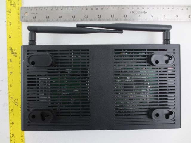
Click to zoom
Application Details
- Equipment Class
- DTS - Digital Transmission System
- Date of Grant
- Jul 31, 2014
- Application Purpose
- Original Equipment
- Date of Application
- Jul 31, 2014
- Equipment Note
- F2300-Wireless 11ac Ethernet Gateway
- Frequency Range
- 2422.00000000 - 2452.00000000
- Company
- Actiontec Electronics Inc
- Country
- United States
Documents & Files
Document Text
Text extracted from the exhibit documents filed with the FCC. Open a document above to read the original.
Users Manual
Actiontec Electronics, Inc. 760 North Mary Ave., Sunnyvale, CA 94085 USA Wireless 11ac Ethernet Gateway Model #: F2300 Quick Start Guide Version: 2.0 (Draft to be review) 1 Connect the Gateway to a Computer 1. Get F2300 from the Quick Start Kit and take it out of the bag. 2. Get the Power Cord from your DSL Quick Start Kit. (Power Adapter External 12VDC, 2A; Model: STD-12020U1 by Actiontec) 3. Plug the smaller end of the Power Cord into the Black Port on the back of the Gateway. 4. Plug the larger end of the Power Cord into a Power Outlet. 5. Make sure the Power Switch is On. 6. Make sure the Power Light on the Gateway is SOLID Green. 7. Get the Yellow Cable 8. Plug one end of the Yellow Cable into any of the Yellow Ports on the back of the Wireless Ethernet Gateway. 9. Make sure that your computer is turned on. Then, plug the other end of the Yellow Cable into the Ethernet Port on the back of the computer. An Ethernet Port looks similar to a regular Phone Jack, but is slightly larger. 10. Make sure that 1 of the 4 Ethernet lights on the Gateway is Green. This may take a few moments. 11. Get the Ethernet Cable from your Quick Start Kit. 12. Plug one end of the Ethernet Cable into the white Ethernet Port located on the back of the Gateway. 13. Plug the other end of the Ethernet Cable into the Ethernet Port provided by your Internet Service Provider. 14. Make sure that that Power and WAN Ethernet Lights are solid Green. This may take up to 30 seconds. Configure the Gateway 1. Open a Web Browser (FireFox or Internet Explorer, for example). In the address bar, enter http://192.168.254.254 then press Enter on the keyboard. 2. Following the Wizard to configure the Gateway. Congratulations you are now connected! 2 Specifications 1. Features • Supports Plug-and-Play installation. • Compliant with IEEE 802.3 Ethernet standard. • Supports 10BaseT and 100BaseT and Gigabit. • 2.4 GHz IEEE 802.11n • 5GHz IEEE 802.11ac/11n • Supports 20 MHz channels with optional SGI • Full IEEE 802.11 b/g/n legacy compatibility with enhanced performance Comprehensive wireless network security support that includes WPA, WPA2, and AES encryption/decryption coupled with TKIP and IEEE 802.1X support • Support 802.11b and Draft STD 802.11g Modulation. • 802.11b Data Rates: 11Mbit/s, 5.5Mbit/s, 2Mbit/s, 1Mbit/s (And 22Mbit/s with PBCC); • 802.11g Data Rates: 6Mbit/s, 9Mbit/s, 12Mbit/s, 18Mbit/s, 24Mbit/s, 36Mbit/s, 48Mbit/s, 54Mbit/s. • 802.11g Data Rates: 65Mbit/s, 130Mbit/s 2. Power requirements • Operating voltage: +12V +/- 5% @ 2A max • Power Dissipation Active: 12V DC @ xxx mA (typical) 3. Environmental Operating Range • Operating temperature: 0º C to 40º C (32º F to 104º F) • Humidity: 10-85%, non-condensing 4. Dimension and Weight • 10 2/1” (L) x 5 1/2” (W) x 1 7/8” (H) 1.35 lb. 5. Certifications • FCC Part 15 Class B, Class C and Class E • Safety UL/cUL 3 General Regulatory and Compliance Notices Important Safety Instructions If applicable, when using telephone equipment, basic safety precautions should always be followed to reduce the risk of fire, electrical shock, and personal injury, including the following: • Do not use this product near water –for example, near a bathtub, kitchen sink, laundry tub, or swimming pool, or in a wet basement; • Avoid using a telephone (other than a cordless type) during an electrical storm, as there may be a remote risk of electrical shock due to lightning; • Do not use the telephone to report a gas leak in the vicinity of the leak; • Use only the power cord and batteries indicated in this manual; • Do not dispose of batteries in fire, as they may explode –check with local codes for possible special disposal instructions. Telephone Line Cord Caution To reduce the risk of fire, use only No. 26 AWG or larger (e.g., 24 AWG) UL Listed or CSA Certified Telecommunication Line Cord. Coaxial Cable If applicable, the coaxial cable screen shield needs to be connected to the Earth at the building entrance per ANSI/NFPA 70, the National Electrical Code (NEC), in particular Section 820.93, “Grounding of Outer Conductive Shield of a Coaxial Cable,” or in accordance with local regulation. For Audio/Video Apparatus This reminder is provided to call the CATV system installer's attention to Section 820.93 of the National Electric Code (NEC), which provides guidelines for proper grounding and, in particular, specifies that the coaxial cable shield shall be connected to the grounding system of the building, as close to the point of cable entry as practical. Please heed all warnings; read, keep and follow all instructions. Do not use this apparatus near water and only clean with dry cloth. Do not block any ventilation openings. Install in accordance with the manufacturer's instructions. Do not install near any heat sources such as radiators, heat registers, stoves, or other apparatus including amplifiers that produce heat. FCC Class B Equipment This equipment has been tested and found to comply with the limits for a Class B digital device, pursuant to Part 15 of the FCC Rules. These limits are designed to provide reasonable protection against harmful interference in a residential installation. This equipment generates, uses and can radiate radio frequency energy and, if not installed and used in accordance with the instructions, may cause harmful interference to radio communications. However, there is no guarantee that interference will not occur in a particular installation. If this equipment does cause harmful interference to radio or television reception, which can be determined by turning the equipment off and on, the user is encouraged to try and correct the interference by implementing one or more of the following measures: • Reorient or relocate the receiving antenna; • Increase the separation between the equipment and receiver; • Connect the equipment to an outlet on a circuit different from that to which the receiver is connected; • Consult the dealer or an experience radio or television tech…
Text truncated - open the document above for the full version.
Cover Letter(s)
Actiontec Electronics, Inc. 760 North Mary Avenue • Sunnyvale • CA • 94085 • USA Phone (408) 752-7700 • Fax (408) 541-9003 • www.actiontec.com FCC Authorization July 14, 2014 FEDERAL COMMUNICATIONS COMMISSIONS Authorization and Evaluation Division 7435 Oakland Mills Road Columbia, MD 21046 Subject: Agent Authorization To whom it may concern: We, Actiontec Electronics Inc., the undersigned, hereby authorizes Bay Area Compliance Laboratories Corporation to act on its behalf in all matters relating to application for Equipment authorization, including the signing of all documents relating to these matters. All acts carried out by Bay Area Compliance Laboratory Corporation on our behalf shall have the same effect as our own action. We, the undersigned, hereby certify that we are not subject to a denial of federal benefits, that includes FCC benefits, pursuant to Section 5301 of the Anti-Drug Abuse Act of 1988, 21 U.S.C. 853(a). This authorization is valid until further written notice from the applicant. Sincerely, Angela Yao/Sr. Program Manager Phone: (408) 752-7700 Fax: (408) 541-9003 Email: [email protected] Solutions for the Digital Life™
Cover Letter(s)
Actiontec Electronics, Inc. 760 North Mary Avenue • Sunnyvale • CA • 94085 • USA Phone (408) 752-7700 • Fax (408) 541-9003 • www.actiontec.com FCC Confidential Authorization July 14, 2014 FEDERAL COMMUNICATIONS COMMISSIONS Authorization and Evaluation Division 7435 Oakland Mills Road Columbia, MD 21046 Subject: Confidentiality Request regarding application for certification of FCC ID: LNQF2300 In accordance with Sections 0.457 and 0.459 of the Commission’s Rules, Actiontec Electronics Inc., hereby requests long-term confidential treatment of information accompanying this application as outlined below: • Block Diagram • Schematics • Operation Description The above materials contain proprietary and confidential information not customarily released to the public. The public disclosure of these materials provides unjustified benefits to its competitors in the market. Sincerely, Angela Yao/Sr. Program Manager Phone: (408) 752-7700 Fax: (408) 541-9003 Email: [email protected] Solutions for the Digital Life™
External Photos
Actiontec Electronics Inc. FCC ID: LNQF2300 Report Number: R14062615-247 Page 77 of 84 FCC Part 15C Test Report 15 Exhibit C – EUT Photographs 15.1 EUT – Top View 15.2 EUT – Front View Actiontec Electronics Inc. FCC ID: LNQF2300 Report Number: R14062615-247 Page 78 of 84 FCC Part 15C Test Report 15.3 EUT – Left Side View 15.4 EUT – Right Side View Actiontec Electronics Inc. FCC ID: LNQF2300 Report Number: R14062615-247 Page 79 of 84 FCC Part 15C Test Report 15.5 EUT – Rear Side View 15.6 EUT – Bottom Side View
Internal Photos
Actiontec Electronics Inc. FCC ID: LNQF2300 Report Number: R14062615-247 Page 80 of 84 FCC Part 15C Test Report 15.7 EUT – Open Shielded Top View 15.8 EUT – Board Shielded Top View Actiontec Electronics Inc. FCC ID: LNQF2300 Report Number: R14062615-247 Page 81 of 84 FCC Part 15C Test Report 15.9 EUT – Board Shielded Bottom View 15.10 EUT – Board Unshielded Top View Actiontec Electronics Inc. FCC ID: LNQF2300 Report Number: R14062615-247 Page 82 of 84 FCC Part 15C Test Report . 15.11 EUT – Unshielded Board Bottom View 15.12 EUT – RF 5 GHz Module Top View Actiontec Electronics Inc. FCC ID: LNQF2300 Report Number: R14062615-247 Page 83 of 84 FCC Part 15C Test Report 15.13 EUT – RF 5 GHz Module Bottom View 15.14 EUT – AC/DC Power Adapter Actiontec Electronics Inc. FCC ID: LNQF2300 Report Number: R14062615-247 Page 84 of 84 FCC Part 15C Test Report 15.15 EUT – Antenna port (reverse male SMA) --- END OF REPORT ---
RF Exposure Info
Actiontec Electronics Inc. FCC ID: LNQF2300 Report Number: R14062615-247 Page 11 of 84 FCC Part 15C Test Report 4 FCC §15.247 (i) & §2.1091 – RF Exposure 4.1 Applicable Standard According to FCC §15.247(i) and §1.1307(b)(1), systems operating under the provisions of this section shall be operated in a manner that ensures that the public is not exposed to radio frequency energy level in excess of the Commission’s guidelines. Limits for General Population/Uncontrolled Exposure Frequency Range (MHz) Electric Field Strength (V/m) Magnetic Field Strength (A/m) Power Density (mW/cm 2 ) Averaging Time (minutes) Limits for General Population/Uncontrolled Exposure 0.3-1.34 614 1.63 * (100) 30 1.34-30 824/f 2.19/f * (180/f 2 ) 30 30-300 27.5 0.073 0.2 30 300-1500 / / f/1500 30 1500-100,000 / / 1.0 30 f = frequency in MHz * = Plane-wave equivalent power density 4.2 MPE Prediction Predication of MPE limit at a given distance, Equation from OET Bulletin 65, Edition 97-01 S = PG/4R² Where: S = power density P = power input to antenna G = power gain of the antenna in the direction of interest relative to an isotropic radiator R = distance to the center of radiation of the antenna 4.3 MPE Results 2.4 GHz Band: Maximum peak output power at antenna input terminal (dBm): 27.35 Maximum peak output power at antenna input terminal (mW): 543.25 Prediction distance (cm): 20 Prediction frequency (MHz): 2437 Maximum Antenna Gain, typical (dBi): 5 Maximum Antenna Gain (numeric): 3.162 Power density of prediction frequency at 20.0 cm (mW/cm 2 ): 0.342 MPE limit for uncontrolled exposure at prediction frequency (mW/cm 2 ): 1.0 Actiontec Electronics Inc. FCC ID: LNQF2300 Report Number: R14062615-247 Page 12 of 84 FCC Part 15C Test Report 5 GHz Module: Maximum peak output power at antenna input terminal (dBm): 25.51 Maximum peak output power at antenna input terminal (mW): 355.63 Prediction distance (cm): 20 Prediction frequency (MHz): 5240 Maximum Antenna Gain, typical (dBi): 1.9 Maximum Antenna Gain (numeric): 1.54 Power density of prediction frequency at 20.0 cm (mW/cm 2 ): 0.109 MPE limit for uncontrolled exposure at prediction frequency (mW/cm 2 ): 1.0 Radio Mode Frequency (MHz) Max Antenna Gain (dBi) Max Conducted Power (dBm) Power Density @ 20 cm (mW/cm 2 ) % of MPE 2.4 GHz 2437 5 27.35 0.342 34.2% 5 GHz 5240 1.9 25.51 0.109 11% The device is compliant with the requirement MPE limit for uncontrolled exposure.
Test Report
Note: This test report is prepared for the customer shown above and for the device described herein. It may not be duplicated or used in part without prior written consent from Bay Area Compliance Laboratories Corp. This report must not be used by the customer to claim product certification, approval, or endorsement by A2LA*, NIST, or any agency of the Federal Government. * This report may contain data that are not covered by the A2LA accreditation and are marked with an asterisk “*” (Rev.2) FCC PART 15, SUBPART C TEST AND MEASUREMENT REPORT For Actiontec Electronics Inc. 760 N. Mary Avenue, Sunnyvale, CA 94085, USA FCC ID: LNQF2300 Report Type: Original Report Product Type: Wireless 11ac Ethernet Gateway Prepared By Isaac Aguilar Test Engineer Report Number R14062615-247 Report Date 2014-07-29 Reviewed By Bo Li Test Engineer Bay Area Compliance Laboratories Corp. 1274 Anvilwood Avenue, Sunnyvale, CA 94089, USA Tel: (408) 732-9162 Fax: (408) 732-9164 Actiontec Electronics Inc. FCC ID: LNQF2300 Report Number: R14062615-247 Page 2 of 84 FCC Part 15C Test Report TABLE OF CONTENTS 1 General Description ..................................................................................................................................................... 5 1.1 Product Description for Equipment Under Test (EUT) ...................................................................................... 5 1.2 Mechanical Description of EUT ......................................................................................................................... 5 1.3 Objective ............................................................................................................................................................. 5 1.4 Related Submittal(s)/Grant(s) ............................................................................................................................. 5 1.5 Test Methodology ............................................................................................................................................... 5 1.6 Measurement Uncertainty ................................................................................................................................... 5 1.7 Test Facility ........................................................................................................................................................ 6 2 System Test Configuration.......................................................................................................................................... 8 2.1 Justification ......................................................................................................................................................... 8 2.2 EUT Exercise Software....................................................................................................................................... 8 2.3 Special Equipment .............................................................................................................................................. 8 2.4 Equipment Modifications.................................................................................................................................... 8 2.5 Local Support Equipment ................................................................................................................................... 8 2.6 EUT Internal Configuration Details .................................................................................................................... 9 2.7 Interface Ports and Cables .................................................................................................................................. 9 2.8 Power Supply List and Details ............................................................................................................................ 9 3 Summary of Test Results ............................................................................................................................................ 10 4 FCC §15.247 (i) & §2.1091 – RF Exposure ................................................................................................................ 11 4.1 Applicable Standard .......................................................................................................................................... 11 4.2 MPE Prediction ................................................................................................................................................. 11 4.3 MPE Results ..................................................................................................................................................... 11 5 FCC §15.203 – Antenna Requirements ...................................................................................................................... 13 5.1 Applicable Standard .......................................................................................................................................... 13 5.2 Antenna List ...................................................................................................................................................... 13 6 FCC §15.207– AC Line Conducted Emissions .......................................................................................................... 14 6.1 Applicable Standards ........................................................................................................................................ 14 6.2 Test Setup ......................................................................................................................................................... 14 6.3 Test Procedure .................................................................................................................................................. 14 6.4 Test Setup Block Diagram ..................................................................................................…
Text truncated - open the document above for the full version.
Test Setup Photos
Actiontec Electronics Inc. FCC ID: LNQF2300 Report Number: R14062615-247 Page 73 of 84 FCC Part 15C Test Report 14 Exhibit B – Test Setup Photographs 14.1 Conducted Emissions - AC/DC Adapter Powered Front View 14.2 Conducted Emissions AC/DC Adapter Powered Side View Actiontec Electronics Inc. FCC ID: LNQF2300 Report Number: R14062615-247 Page 74 of 84 FCC Part 15C Test Report 14.3 Radiated Emission Below 1 GHz Front View at 3 Meter 14.4 Radiated Emission Below 1 GHz Rear View at 3 Meter Actiontec Electronics Inc. FCC ID: LNQF2300 Report Number: R14062615-247 Page 75 of 84 FCC Part 15C Test Report 14.5 Radiated Emission Above 1 GHz Front View at 3 Meter 14.6 Radiated Emission Above 1 GHz Rear View at 3 Meter Actiontec Electronics Inc. FCC ID: LNQF2300 Report Number: R14062615-247 Page 76 of 84 FCC Part 15C Test Report 14.7 Radiated Emission Above 18 GHz Front View at 3 Meter 14.8 Radiated Emission Above 18 GHz Rear View at 3 Meter
Contact Information
Applicant
Zhe Liu(Product Manager)
Test Firm
Bay Area Compliance Laboratories Corp.Lisa Tang
Technical Specifications
| # | Rule Parts | Frequency Range | Power Output |
|---|---|---|---|
| 2 | 15C | 2.42 GHz - 2.45 GHz | 542.70 mW |
Other Applications from Actiontec Electronics Inc

LNQWF672
Dec 26, 2025Wi-Fi 7 Outdoor Mesh AP
Equipment Class
DTS - Digital Transmission System
LNQ-WF670G
Dec 09, 2025Wi-Fi 7 Outdoor Mesh AP
Equipment Class
DTS - Digital Transmission SystemLNQ-WF815-2
Apr 14, 2024Tri-band Wi-Fi 6E Wireless AP
Equipment Class
DTS - Digital Transmission System
LNQ-WF825
Mar 24, 2024Tri-band Wi-Fi 7 Wireless AP
Equipment Class
6ID - 15E 6 GHz Low Power Indoor Access Point
LNQ-WF810G-2
Mar 23, 2024Wi-Fi 6E Mesh Extender
Equipment Class
DTS - Digital Transmission System