LNQGT70154Mbps Wireless Gateway and Access Point
Actiontec Electronics Inc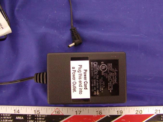
Click to zoom
Application Details
- Equipment Class
- DTS - Digital Transmission System
- Date of Grant
- Dec 30, 2003
- Application Purpose
- Original Equipment
- Date of Application
- Dec 30, 2003
- Equipment Note
- 54Mbps Wireless Gateway and Access Point
- Frequency Range
- 2412.00000000 - 2462.00000000
- Company
- Actiontec Electronics Inc
- Country
- United States
Documents & Files
Document Text
Text extracted from the exhibit documents filed with the FCC. Open a document above to read the original.
Users Manual
Questions? Call toll-free at 1-800-247-7285 1 Connect the Gateway to a Computer Step 3 Plug the smaller end of the Power Cordinto the Black Porton the back of the Gateway. Step 4 Plug the larger end of the Power Cordinto a Power Outlet . Step 1 Get the Wireless DSL Gateway from your DSL Quick Start Kit and take it out of the bag. Step 2 Get theBlack Bagand remove the Power Cordfrom the bag. Wireless DSL Gateway Power Cord Power Cord Black Port Step 10Get the Green DSL Cable out of the Black Bag. Step 11Plug one end of the Green Cableinto the Green Port on the back of the Gateway. Questions? Call toll-free at 1-800-247-7285 Step 5 Confirm the Power Light on the Gateway is Green. Power Light on Wireless DSL Gateway Step 13Confirm that the Powerand DSL Lightsare solid Green. This may take up to 30 seconds. Power & DSL Lights on Wireless DSL Gateway Step 6Get the Yellow Cable. Step 7 Plug one end of the Yellow Cableinto the Yellow Port on the back of the Wireless DSL Gateway. Questions? Call toll-free at 1-800-247-7285 Step 8 Plug the other end of the Yellow Cablein the Ethernet Porton the back of the computer. An Ethernet Portlooks similar to a regular Phone Jack, but is slightly larger. Note:If the Ethernet Network Light does NOTturn green, make sure the Yellow Cable is properly connected on both ends. Step 9Confirm that the Ethernet lighton the Gateway is Green. This may take a few moments. Ethernet Light on Wireless DSL Gateway Step 12 Plug the other end of the Green Cableinto the Phone Jack closest to your computer. Questions? Call toll-free at 1-800-247-7285Questions? Call toll-free at 1-800-247-7285 Note:If the DSL Light continues to blink, make sure you received notification from your DSL Service Provider that your DSL service is On. Otherwise, contact your DSL Service Provider immediately. Questions? Call toll-free at 1-800-247-7285Questions? Call toll-free at 1-800-247-7285Questions? Call toll-free at 1-800-247-7285 Before proceeding, make sure you have received notification from your phone company that your DSL line is active. Note:If you have a Macintosh Computer, see section 6, “Setup a Macintosh Computer,” at the end of this Quick Start Guide. Step 1 Open a Web browser (Netscape Navigator or Internet Explorer, for example). In the address bar, enter http://192.168.0.1, then press Enteron the keyboard. Step 2 The “Main Menu”screen appears. Select Setup/ Configuration. Step 3 Click Non-Windows Setup in the left-hand column of the “Set Up/Configuration” screen. Step 4 The “Actiontec DSL Modem Setup Page”screen appears. Follow the onscreen instructions. Have your Internet Service Provider (ISP) Worksheet handy and use it to fill in the text boxes in the Actiontec DSL Modem Setup Page. If you have not received your ISP Worksheet, contact your ISP. The Worksheet is provided separately from this kit by your ISP. Step 5 Click Save and Restartat the bottom of the Actiontec DSL Modem Setup Page to save your changes. The Wireless DSL Gateway is now configured and ready for use. For more information regarding technical support, please review the Start Here Guide. If you received a Block of IP addresses from your Internet Service Provider, follow the instructions in Section 4 of this Guide, “Configure a Block of IP Addresses.”Otherwise, go to Section 5, “Configure a Single IP Address.” Security Notice Don’t be a victim! Secure your DSL service from unwanted intrusions. Please refer to the Security section of your User Manual for more information regarding network security. 2 Install the Phone Filters Step 1Unplug your Telephones (or other devices) from their current Phone Jacks. Step 2Open the Clear Bag and remove the Phone Filters from the bag. What are Phone Filters? Phone Filters separate the DSL signal from the voice signal, allowing you to talk on the telephone and be online at the same time. All Deviceswith the same phone number as your DSL Line require Phone Filters. This includes telephones, fax machines, caller ID boxes, and answering machines. Caution:Do Notunplug the Green Cable from the Phone Jack near your Computer. Note:The number and type of Phone Filters included in this kit may vary. Step 3Plug a Phone Filter into every Phone Jackin your house with the same phone number as your DSL Line, and a telephone (or other device) connected to it. If you need additional Phone Filters, contact your DSL Service Provider. Note:If you have a wall-mount telephone, you must install the Wall-Mount Phone Filter. For all other telephones or other devices, use the small Phone Filters. To install a Wall-Mount Phone Filter, see “Installing a Wall-Mount Phone Filter,”below. Step 4Plug one end of the Phone Cord into the Phone Filterand keep the other end attached to the telephone (or other device). Caution:Do Notconnect a Phone Filter into the Phone Jack near your Computer (the Phone Jack into which your Green Cable is plugged). To Install a Telephone next to your Computer: Step 1Find the Phone Cord connected to the Telephonenext to your Computer. Unplug this Phone Cord from the Phone Jack it is currently plugged into (you may have already unplugged the cable during the modem installation process). Keep the other end connected to the Telephone. Phone Jack Phone Cord Note:Do Notunplug the Green cable from the Phone Jack near your computer. Step 2Plug the Phone Cord into the Port marked “Phone”on the back of the Gateway. Do Not plug the Phone Cord into the back of your Computer. Make sure you have connected your Phone to the Gateway exactlyas shown in the picture to the right. Power Outlet Power Cord Note:The phone port on the Gateway includes a built-in microfilter. As a result, no additional filter is needed. Phone Port DSL Cable 1) Remove the wall-mount telephonefrom the wall jack. 2) Open the top and bottom toggles until they snap into the open position. 3) Push the Wall-Mount Phone Filterinto the wall jack, fully inserting the plug on the back of the filter into the wall jack opening. 4) Push t…
Text truncated - open the document above for the full version.
External Photos
EXHIBIT C - EUT EXTERNAL PHOTOGRAPHS EUT - Front View EUT - Rear View Adaptor View
ID Label/Location Info
EXHIBIT A - FCC ID LABEL INFORMATION Proposed FCC ID Label Specifications: Text is black or white in color and is left justified. Labels are silk-screened and shall be “permanently affixed” at a conspicuous location on the EUT. Proposed Label Location on Notebook Rear Side of Notebook / Label Location FCC ID: LNQGT701 This device complies with Part 15 o the FCC Rules. Operation is subject to the following two conditions: (1) this device may not cause harmful interference, and (2) this device must accept any interference received, including interference that may cause undesired operation. 2.1875" 1.0" FCC ID: LNQ802PAG This device complies w ith Part 15 o the FCC Rules. Operation is subject to the following two conditions: (1) this device may not cause harmful interference, and (2) this device must accept any interference received, including interference that m ay cause undesired operation. 2.1875" 1.0"
Internal Photos
EXHIBIT C - EUT INTERNAL PHOTOGRAPHS EUT – Port View EUT – Component View EUT – Solder View Antenna Connection View
Test Report
Note: This test report is specially limited to the above client company and product model only. It may not be duplicated without prior written consent of Bay Area Compliance Laboratory Corporation. This report must not be used by the client to claim product endorsement by NVLAP or any agency of the U.S. Government. FCC PART 15 EMI MEASUREMENT AND TEST REPORT For Actiontec Electronics, Inc. 760 North Mary Ave. Sunnyvale, CA 94086 FCC ID: LNQGT701 2003-12-29 This Report Concerns: Original Report Equipment Type: USB/Ethernet DSL Modem, 54Mbps Wireless Gateway & 54Mbps Wireless Access Point- ITE Test Engineer: Ming Jing / Report No.: R0311181 Test Date: 2003-11-19 Reviewed By: Ling Zhang / Prepared By: Bay Area Compliance Laboratory Corporation (BACL) 230 Commercial Street Sunnyvale, CA 94085 Tel: (408) 732-9162 Fax: (408) 732 9164 Actiontec Electronics, Inc. FCC ID: LNQGT701 Report # R0311181Rpt.doc Page 2 of 49 FCC Part 15.247 Test Report TABLE OF CONTENTS GENERAL INFORMATION.......................................................................................................................................4 PRODUCT DESCRIPTION FOR EQUIPMENT UNDER TEST (EUT) ....................................................................................4 OBJECTIVE...................................................................................................................................................................4 RELATED SUBMITTAL(S)/GRANT(S).............................................................................................................................4 TEST METHODOLOGY..................................................................................................................................................4 TEST FACILITY.............................................................................................................................................................4 SUPPORT EQUIPMENT LIST AND DETAILS....................................................................................................................5 EXTERNAL I/O CABLING LIST AND DETAILS...............................................................................................................5 SYSTEM TEST CONFIGURATION ..........................................................................................................................6 JUSTIFICATION.............................................................................................................................................................6 EUT EXERCISE SOFTWARE..........................................................................................................................................6 SPECIAL ACCESSORIES.................................................................................................................................................6 SCHEMATICS / BLOCK DIAGRAM.................................................................................................................................6 EQUIPMENT MODIFICATIONS.......................................................................................................................................6 CONFIGURATION OF TEST SYSTEM..............................................................................................................................7 TEST SETUP BLOCK DIAGRAM.....................................................................................................................................7 SUMMARY OF TEST RESULTS ...............................................................................................................................8 §1.1307(B)(1) & §2.1093 - RF EXPOSURE.................................................................................................................9 §15.203 - ANTENNA REQUIREMENT....................................................................................................................10 STANDARD APPLICABLE............................................................................................................................................10 ANTENNA CONNECTED CONSTRUCTION....................................................................................................................10 §15.207(A) - CONDUCTED EMISSIONS.................................................................................................................11 MEASUREMENT UNCERTAINTY..................................................................................................................................11 EUT SETUP................................................................................................................................................................11 SPECTRUM ANALYZER SETUP....................................................................................................................................11 TEST EQUIPMENT LIST AND DETAILS.........................................................................................................................11 TEST PROCEDURE......................................................................................................................................................11 SUMMARY OF TEST RESULTS.....................................................................................................................................12 CONDUCTED EMISSIONS TEST DATA.........................................................................................................................12 PLOT OF CONDUCTED EMISSIONS TEST DATA...........................................................................................................12 §15.209(A) - SPURIOUS EMISSION ........................................................................................................................15 STANDARD APPLICABLE.........................................................................................................................................…
Text truncated - open the document above for the full version.
Test Report
Actiontec Electronics, Inc. FCC ID: LNQGT701 Report # R0311181Rpt.doc Page 31 of 49 FCC Part 15.247 Test Report §15.247(a)(2) – 6 DB BANDWIDTH Standard Applicable According to §15.247(a)(2), for direct sequence systems, the minimum 6dB bandwidth shall be at least 500 kHz. Measurement Procedure 1. Check the calibration of the measuring instrument using either an internal calibrator or a known signal from an external generator. 2. Position the EUT without connection to measurement instrument. Turn on the EUT and connect it to measurement instrument. Then set it to any one convenient frequency within its operating range. Set a reference level on the measuring instrument equal to the highest peak value. 3. Measure the frequency difference of two frequencies that were attenuated 6 dB from the reference level. Record the frequency difference as the emission bandwidth. (6 dB bandwidth for DTS) 4. Repeat above procedures until all frequencies measured were complete. Equipment Lists Manufacturer Model No. Description Calibration Date HP 8565EC Spectrum Analyzer 2003-01-22 Measurement Result Environmental Conditions Temperature: 25° C Relative Humidity: 52% ATM Pressure: 1100 mbar Test Result for 802.11b (15.247) Channel Frequency (MHz) Measured (MHz) Measured (kHz) Standard (kHz) Result Low 2412 11.83 1183 ≥ 500 Pass Mid 2437 11.50 1150 ≥ 500 Pass High 2462 11.92 1192 ≥ 500 Pass Actiontec Electronics, Inc. FCC ID: LNQGT701 Report # R0311181Rpt.doc Page 32 of 49 FCC Part 15.247 Test Report Test Result for 802.11g (15.247) Channel Frequency (MHz) Measured (MHz) Measured (kHz) Standard (kHz) Result Low 2412 16.67 1667 ≥ 500 Pass Mid 2437 16.67 1667 ≥ 500 Pass High 2462 16.83 1683 ≥ 500 Pass Actiontec Electronics, Inc. FCC ID: LNQGT701 Report # R0311181Rpt.doc Page 33 of 49 FCC Part 15.247 Test Report Plots of 6dB Bandwidth for 802.11b (15.247) Actiontec Electronics, Inc. FCC ID: LNQGT701 Report # R0311181Rpt.doc Page 34 of 49 FCC Part 15.247 Test Report Plots of 6dB Bandwidth for 802.11g (15.247) Actiontec Electronics, Inc. FCC ID: LNQGT701 Report # R0311181Rpt.doc Page 35 of 49 FCC Part 15.247 Test Report Actiontec Electronics, Inc. FCC ID: LNQGT701 Report # R0311181Rpt.doc Page 36 of 49 FCC Part 15.247 Test Report §15.247(b)(3) - PEAK OUTPUT POWER MEASUREMENT Standard Applicable According to §15.247(b) (3), for systems using digital modulation in 2400-2483.5 MHz: 1 Watt Measurement Procedure 1. Place the EUT on a bench and set it in transmitting mode. 2. Remove the antenna from the EUT and then connect a low loss RF cable from the antenna port to a spectrum analyzer. 3. Add a correction factor to the display. Equipment Lists Manufacturer Model No. Description Calibration Date HP 8565EC Spectrum Analyzer 2003-01-22 Measurement Result Environmental Conditions Temperature: 25° C Relative Humidity: 52% ATM Pressure: 1100 mbar Output Power (15.247) for 802.11b Channel Frequency (MHz) RF Power (dBm) Correction Factor (dB) Corrected RF Power (dBm) Corrected RF Power (W) Limit Low (Ch1) 2412 7.50 7.7 15.20 0.033 1W (30dBm) Mid (Ch7) 2437 7.83 7.7 15.53 0.036 1W (30dBm) High (Ch11) 2462 7.67 7.7 15.37 0.034 1W (30dBm) Note: Correction Factor = 10Log(BW 6dB /RBW) = 10Log(11.8/2) = 7.7 dB Output Power (15.247) for 802.11g Channel Frequency (MHz) RF Power (dBm) Correction Factor (dB) Corrected RF Power (dBm) Corrected RF Power (W) Limit Low (Ch1) 2412 6.50 9.2 15.70 0.037 1W (30dBm) Mid (Ch7) 2437 6.17 9.2 15.37 0.034 1W (30dBm) High (Ch11) 2462 6.33 9.2 15.53 0.036 1W (30dBm) Note: Correction Factor for Turbo Mode = 10 log (BW 6dB /RBW) = 10 log (16.7/2.0) = 9.2 dBm EUT SA Actiontec Electronics, Inc. FCC ID: LNQGT701 Report # R0311181Rpt.doc Page 37 of 49 FCC Part 15.247 Test Report Plots of Peak Output Power for 802.11b (15.247) Actiontec Electronics, Inc. FCC ID: LNQGT701 Report # R0311181Rpt.doc Page 38 of 49 FCC Part 15.247 Test Report Plots of Peak Output Power for 802.11 g (15.247) Actiontec Electronics, Inc. FCC ID: LNQGT701 Report # R0311181Rpt.doc Page 39 of 49 FCC Part 15.247 Test Report Actiontec Electronics, Inc. FCC ID: LNQGT701 Report # R0311181Rpt.doc Page 40 of 49 FCC Part 15.247 Test Report §15.247(c) - 100 KHZ BANDWIDTH OF BAND EDGES Standard Applicable According to §15.247(c), in any 100 kHz bandwidth outside the frequency bands in which the spread spectrum intentional radiator is operating, the radio frequency power that is produced by the intentional radiator shall be at least 20 dB below that in the 100 kHz bandwidth within the band that contains the highest level of the desired power, based on either an RF conducted or a radiated measurement. In addition, radiated emissions which fall in the restricted bands, as defined in §15.205(a), must also comply with the radiated emission limits specified in §15.209(a) see §15.205(c)). Measurement Procedure 1. Check the calibration of the measuring instrument using either an internal calibrator or a known signal from an external generator. 2. Position the EUT without connection to measurement instrument. Turn on the EUT and connect its antenna terminal to measurement instrument via a low loss cable. Then set it to any one measured frequency within its operating range, and make sure the instrument is operated in its linear range. 3. Set both RBW and VBW of spectrum analyzer to 100 kHz with a convenient frequency span including 100kHz bandwidth from band edge. 4. Measure the highest amplitude appearing on spectral display and set it as a reference level. Plot the graph with marking the highest point and edge frequency. 5. Repeat above procedures until all measured frequencies were complete. Equipment Lists Manufacturer Model No. Description Calibration Date HP 8565EC Spectrum Analyzer 2003-01-22 Measure Results Environmental Conditions Temperature: 25° C Relative Humidity: 52% ATM Pressure: 1100 mbar Please refer to following pages for plots of band edge. Actiontec Electronics, Inc. FCC ID: LNQGT701 Report # R0311181Rpt.doc Page 41 of 49 FCC Part 1…
Text truncated - open the document above for the full version.
Test Setup Photos
EXHIBIT B - TEST SETUP PHOTOGRAPHS Conducted Emission - Front View Conducted Emission - Side View Radiated Emission - Front View Radiated Emission - Rear View
Contact Information
Applicant
Brian Henrichs(President)
Test Firm
Bay Area Compliance LaboratoryJohn Chan
Technical Specifications
| # | Rule Parts | Frequency Range | Power Output |
|---|---|---|---|
| 2 | 15C | 2.41 GHz - 2.46 GHz | 37.00 mW |
Other Applications from Actiontec Electronics Inc

LNQWF672
Dec 26, 2025Wi-Fi 7 Outdoor Mesh AP
Equipment Class
DTS - Digital Transmission System
LNQ-WF670G
Dec 09, 2025Wi-Fi 7 Outdoor Mesh AP
Equipment Class
DTS - Digital Transmission SystemLNQ-WF815-2
Apr 14, 2024Tri-band Wi-Fi 6E Wireless AP
Equipment Class
DTS - Digital Transmission System
LNQ-WF825
Mar 24, 2024Tri-band Wi-Fi 7 Wireless AP
Equipment Class
6ID - 15E 6 GHz Low Power Indoor Access Point
LNQ-WF810G-2
Mar 23, 2024Wi-Fi 6E Mesh Extender
Equipment Class
DTS - Digital Transmission System