LNQMWTV2TXMyWirelessTV 2 Wireless HD Transmitter
Actiontec Electronics Inc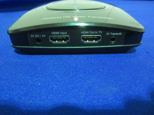
Click to zoom
Application Details
- Equipment Class
- DTS - Digital Transmission System
- Date of Grant
- Jul 01, 2014
- Application Purpose
- Original Equipment
- Date of Application
- Jul 01, 2014
- Equipment Note
- MyWirelessTV 2 Wireless HD Transmitter
- Frequency Range
- 5755.00000000 - 5795.00000000
- Company
- Actiontec Electronics Inc
- Country
- United States
Documents & Files
Document Text
Text extracted from the exhibit documents filed with the FCC. Open a document above to read the original.
Users Manual
MyWirelessTV allows video and audio to be sent from video source to the TV wirelessly. Therefore, you have the freedom to place the TV virtually anywhere within the home and enjoy live TV without the wiring mess. Make sure you identify which ‘source device’ that you want to connect to the Transmitter. Video from that ‘source device’ will be transmitted to your receiver box(s). INSTALLATIONfor the MyWirelessTV is EASY. Both units come pre-paired to work with each other. All you need to do is connect the cables according to the diagram or, if you want, follow the detailed step-by-step instructions. A How MyWirelessTV Works Step 1b(Optional) If the source device is previously connected to an HDTV, unplug the HDMI cable from the back of the source, then plug the free end of the HDMI cable into the HDMI port that labels Out-to-TV on the back of the Transmitter. Step 1cOtherwise, get an HDMI cable from MyWirelessTV 2 Kit. Plug one end into the HDMI Inputport on the back of the Transmitter. Step 1aSelect the Source Device (i.e. a Cable/Satellite set-top box or Blu-ray player) you wish to transmit signal to the TV, and power off that device. Get the Wireless HD Video Transmitter unit from MyWirelessTV 2 Kit and follow the steps below. B Setting Up Transmitter & Receiver Step 3aGet the Wireless HD Video Receiver, HDMI cable and power supply. Go to the TV that you want to connect. Step 3bPlug one end of this HDMI cable into an HDMI port on the HDTV. Step 2aGet the power supply from MyWirelessTV 2 Kit. Plug the smaller end of the power supply into the 5VDC port on the back of the Transmitter. Step 3dTurn on the TV and switch the source to the HDMI input that the Receiver is connected to. Step 4aPlug the smaller end of the power supply into the 5VDC port on the back of the Receiver. Step 3cPlug the other end of the HDMI cable into the HDMI port labels Out-to-TVon the back of the Re- ceiver. Step 4bPlug the larger end of the power supply into a power outlet. Step 4cMake sure the Power Light on the Receiver is SOLID Green. Flip this Quick Start Guide over to continue NEXT Note:Only use power adapter, Actiontec Electronics Inc., Model # WA-10P05FU Note:The LINK light will blink. Up to 150 ft. range* RECEIVER MWTV2RX TRANSMITTER MWTV2TX HDTV (Optional) (Optional) (Optional) HDTV POWER OUTLET POWER OUTLET SOURCE DEVICE 2 1b 4 3 5 6 Please refer to this illustration while connecting cables Step 4dWait for a bit as the Receiver connects to the Transmitter. The LINK light should show SOLID Green once they’re connected. CAUTION Do NOT place the MyWirelessTV Transmitter or Receiver on top of or near a heat-generating source. *Range subject to change. Walls, ceilings and floors may reduce the wireless range. Step 1dPlug the other end into the HDMI port on the Source Device. Step 2bPlug the larger end of the power supply into a power outlet. Step 2cVerify the Power Light on the Transmitter is SOLID Green. Note:If the Transmitter and Receiver are in the same room, you may skip to Step 1c. Step 2aGet the power supply from MyWirelessTV 2 Kit. Plug the smaller end of the power supply into the 5VDC port on the back of the Transmitter. 1c 1d Step 2dNow power on your video Source Device. pic MWTV2_QSG-0530-0731-000-v5_QS sngl pnl 2014/5/5 16:37 页 1 MyWirelessTV 2 Multi-Room Wireless HD Video Kit NEXT Model# MWTV2TX & MWTV2RX D Troubleshooting C Setting Up IR Control (Optional) Quick Start Guide This Quick Start Guide will walk you through the easy steps to set up MyWirelessTV 2 Kit. A How MyWirelessTV Works B Setting Up Transmitter & Receiver C Setting Up IR Control D Troubleshooting You will need the following items from your MyWirelessTV 2 kit: • Wireless HD Transmitter • Wireless HD Receiver • Two (2) Power Supplies • Two (2) HDMI Cables • IR Blaster Cable • IR Receiver Extension Cable © 2014 Actiontec Electronics, Inc. Actiontec, Actiontec Installation Buddy, Creative Solutions for the Digital Life, and the Actiontec logo are trademarks or registered trademarks of Actiontec Electronics, Inc. in the U.S. or other countries. All other names are properties of their respective owners. Product photo may differ from actual product, however functionality remains as stated above. Specifications are subject to change without notice. FREQUENTLY ASKED QUESTIONS 1 Q Do I must connect a TV to the Transmitter’s HDMI Out- to-TV port? A No. This step is optional. 2 Q I’m not seeing video on the TV that’s connected to the Transmitter. A Check the power and connection from the video source to the Transmitter, and the connection from the Transmitter to TV. 3 Q I’m not seeing video on the TV that’s connected to the Receiver. A Check the power and connection from Receiver to the TV, and make sure the correct source input is selected on the TV. 4 Q The audio and video on the Receiver’s TV seems slower than on Transmitter’s TV. A This is expected since the Receiver receives AV transmis- sion from the Transmitter over the air. Your HDTVs and cable/satellite box should be connected as shown in the previous diagram. You can now start enjoying HDTV anywhere you want it! Step 6bPlug the IR Extender cable’s green connector in to the Green port on the back of the Receiver. 5 Q The video quality is poor and sometimes there’s no video displays on the Receiver’s TV. A You may need to adjust the orientation of the Transmitter and Receiver units, and direct them to be facing each other. You can view the MyWirelessTV connection strength on the Menu page of the Receiver. To access the Menu page, press the MENU button once on the Receiver. 6 Q I cannot control the source device with its remote con- trol, via the MyWirelessTV Receiver OR the source de- vice is slow to respond to the remote control. A Make sure the IR Blaster cable is connected to the Trans- mitter “IR Transmit” port, and the sensor is mounted di- rectly on top of the source device’s IR Sensor window. Also make sure the Receiver or the IR Receiver cable sen- sor is in line-of-sight of t…
Text truncated - open the document above for the full version.
Cover Letter(s)
Actiontec Electronics, Inc. 760 North Mary Avenue • Sunnyvale • CA • 94085 • USA Phone (408) 752-7700 • Fax (408) 541-9003 • www.actiontec.com Solutions for the Digital Life™ FCC Confidential Authorization May 22, 2014 FEDERAL COMMUNICATIONS COMMISSIONS Authorization and Evaluation Division 7435 Oakland Mills Road Columbia, MD 21046 Subject: Confidentiality Request regarding application for certification of FCC ID: LNQMWTV2TX In accordance with Sections 0.457 and 0.459 of the Commission’s Rules, Actiontec Electronics, Inc., hereby requests long‐term confidential treatment of information accompanying this application as outlined below: Block Diagram Schematics Operation Description The above materials contain proprietary and confidential information not customarily released to the public. The public disclosure of these materials provides unjustified benefits to its competitors in the market. Sincerely, Angela Yao/Sr. Program Manager Phone: (408) 752‐7700 Fax: (408) 541‐9003 Email: [email protected]
External Photos
EXHIBIT B - EUT EXTERNAL PHOTOGRAPHS EUT – All View EUT – Left Side View EUT – Right Side View EUT – USB Port View EUT – HDMI Port View EUT – Adapter Label View
ID Label/Location Info
EXHIBIT A - FCC ID LABELING AND LOCATION FCC ID Label Proposed FCC ID Location The label shown shall be permanently affixed at a conspicuous location on the device and be readily visible to the user at the time purchase (Labeling requirements per 2.925) Label here
Internal Photos
EXHIBIT C - EUT INTERNAL PHOTOGRAPHS EUT – Uncover View EUT – Main Board Top View EUT – Main Board Top Shielding Off View EUT –Main Board Bottom View EUT – RF Chip View EUT – Antenna 1 View EUT – Antenna 2 View
Test Report
Note: This test report is prepared for the customer shown above and for the device described herein. It may not be duplicated or used in part without prior written consent from Bay Area Compliance Laboratories Corp. (Dongguan). This report is valid only with a valid digital signature. The digital signature may be available only under the Adobe software above version 7.0. FCC PART 15.247 TEST REPORT For Actiontec Electronics, Inc. 760 North Mary Avenue Sunnyvale, CA 94085, USA FCC ID: LNQMWTV2TX Report Type: Original Report Product Type: MyWirelessTV 2 Wireless HD Transmitter Test En gineer: Dean Liu Re port Number: R2SH140320052-00A Re port Date: 2014-05-19 Reviewed By: Sula Huang RF En gineer Test Laboratory: Bay Area Compliance Laboratories Corp. (Dongguan) No.69 Pulongcun, Puxinhu Industrial Zone, Tangxia, Dongguan, Guangdong, China Tel: +86-769-86858888 Fax: +86-769-86858891 www.baclcorp.com.cn Bay Area Compliance Laboratories Corp. (Dongguan) Report No.: R2SH140320052-00A FCC Part 15.247 Page 2 of 158 TABLE OF CONTENTS GENERAL INFORMATION ....................................................................................................................................... 4 PRODUCT DESCRIPTION FOR EQUIPMENT UNDER TEST (EUT) ..................................................................................... 4 ANTENNA INFORMATION .............................................................................................................................................. 4 OBJECTIVE ................................................................................................................................................................... 4 RELATED SUBMITTAL(S)/GRANT(S) ............................................................................................................................. 4 TEST METHODOLOGY .................................................................................................................................................. 4 TEST FACILITY ............................................................................................................................................................. 5 SYSTEM TEST CONFIGURATION .......................................................................................................................... 6 DESCRIPTION OF TEST CONFIGURATION ...................................................................................................................... 6 EQUIPMENT MODIFICATIONS ....................................................................................................................................... 6 EUT EXERCISE SOFTWARE .......................................................................................................................................... 7 SUPPORT EQUIPMENT LIST AND DETAILS .................................................................................................................... 8 EXTERNAL CABLE ........................................................................................................................................................ 8 BLOCK DIAGRAM OF TEST SETUP ................................................................................................................................ 8 SUMMARY OF TEST RESULTS ............................................................................................................................... 9 FCC §15.247 (i) & §1.1310 & §2.1091- MAXIMUM PERMISSIBLE EXPOSURE (MPE) ....................................... 10 APPLICABLE STANDARD ............................................................................................................................................ 10 FCC §15.203 - ANTENNA REQUIREMENT ........................................................................................................... 11 APPLICABLE STANDARD ............................................................................................................................................ 11 ANTENNA CONNECTOR CONSTRUCTION .................................................................................................................... 11 FCC §15.207 (a) – AC LINE CONDUCTED EMISSIONS ..................................................................................... 12 APPLICABLE STANDARD ............................................................................................................................................ 12 MEASUREMENT UNCERTAINTY .................................................................................................................................. 12 EUT SETUP ................................................................................................................................................................ 12 EMI TEST RECEIVER SETUP ....................................................................................................................................... 13 TEST PROCEDURE ...................................................................................................................................................... 13 CORRECTED AMPLITUDE & MARGIN CALCULATION ................................................................................................. 13 TEST EQUIPMENT LIST AND DETAILS ......................................................................................................................... 14 TEST RESULTS SUMMARY .......................................................................................................................................... 14 TEST DATA ................................................................................................................................................................ 14 FCC §15.209, §15.205 & §15.247(d) - SPURIOUS EMISSIONS ............................................................................. 17 APPLICABLE STANDARD ..............................................................…
Text truncated - open the document above for the full version.
Test Setup Photos
EXHIBIT D - TEST SETUP PHOTOGRAPHS Conducted Emission - Front View Conducted Emission - Side View Radiated Emission – Front View (Below 1GHz) Radiated Emission – Rear View (Below 1GHz) Radiated Emission – Front View (Above 1GHz Distance 1.5m) Radiated Emission – Rear View (Above 1GHz Distance 1.5m) Radiated Emission – Front View (Above 1GHz Distance 3.0m) Radiated Emission – Rear View (Above 1GHz Distance 3.0m)
Contact Information
Applicant
Zhe Liu(Product Manager)
Test Firm
Bay Area Compliance Laboratories Corp. (Dongguan)John Chan
[email protected]86-769-86858888
Technical Specifications
| # | Rule Parts | Frequency Range | Power Output |
|---|---|---|---|
| 4 | 15C | 5.75 GHz - 5.79 GHz | 44.00 mW |
Other Applications from Actiontec Electronics Inc

LNQWF672
Dec 26, 2025Wi-Fi 7 Outdoor Mesh AP
Equipment Class
DTS - Digital Transmission System
LNQ-WF670G
Dec 09, 2025Wi-Fi 7 Outdoor Mesh AP
Equipment Class
DTS - Digital Transmission SystemLNQ-WF815-2
Apr 14, 2024Tri-band Wi-Fi 6E Wireless AP
Equipment Class
DTS - Digital Transmission System
LNQ-WF825
Mar 24, 2024Tri-band Wi-Fi 7 Wireless AP
Equipment Class
6ID - 15E 6 GHz Low Power Indoor Access Point
LNQ-WF810G-2
Mar 23, 2024Wi-Fi 6E Mesh Extender
Equipment Class
DTS - Digital Transmission System