LNQR3000Wireless Router
Actiontec Electronics Inc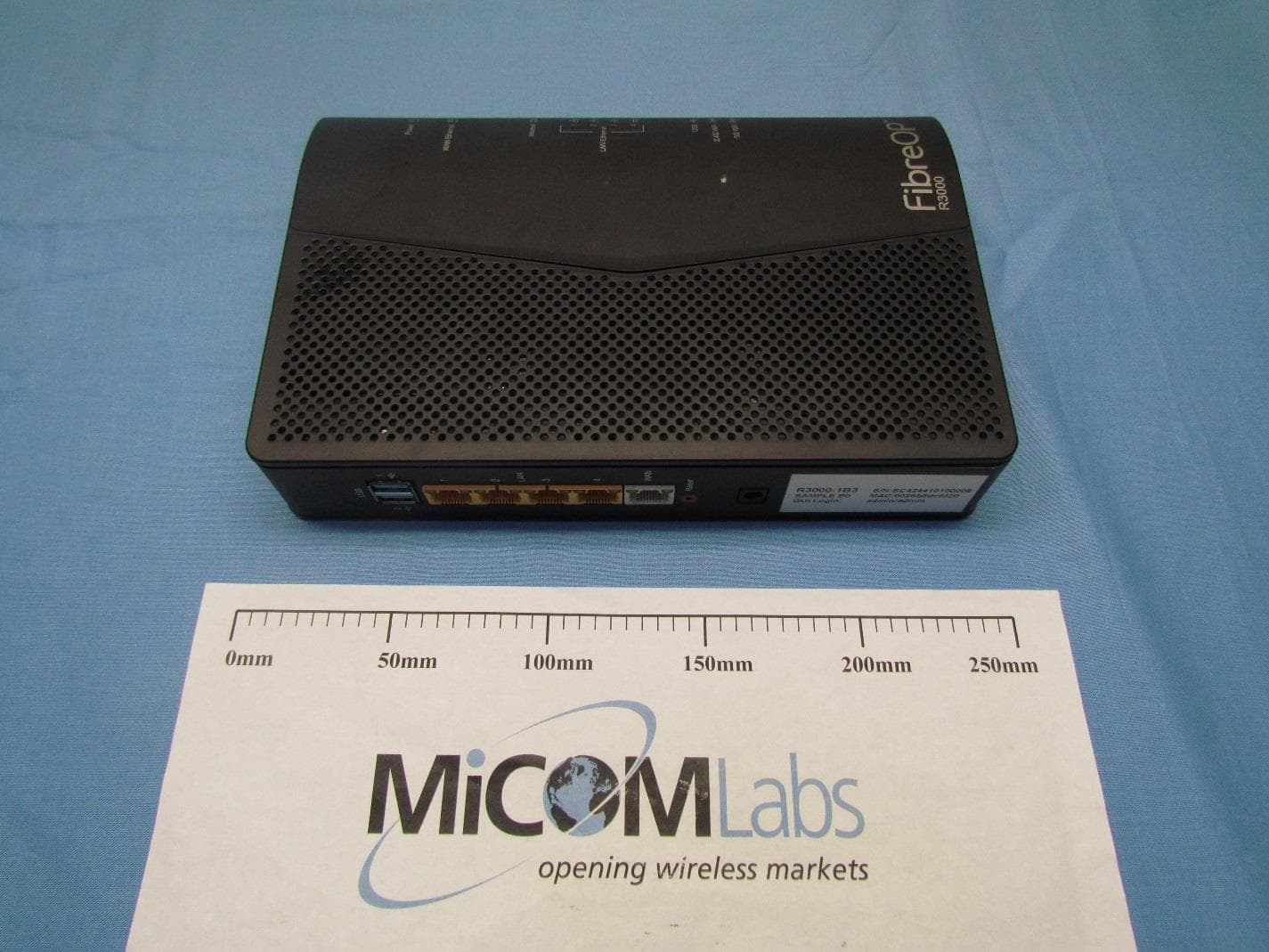
Click to zoom
Application Details
- Equipment Class
- DTS - Digital Transmission System
- Date of Grant
- Mar 01, 2015
- Application Purpose
- Original Equipment
- Date of Application
- Feb 25, 2015
- Equipment Note
- Wireless Router
- Frequency Range
- 2412.00000000 - 2462.00000000
- Company
- Actiontec Electronics Inc
- Country
- United States
Documents & Files
Document Text
Text extracted from the exhibit documents filed with the FCC. Open a document above to read the original.
Users Manual
Actiontec Electronics, Inc. 760 North Mary Ave., Sunnyvale, CA 94085 USA 11ac Wireless Router Model #: R3000 Quick Start Guide Version: 0.1 1 Connect the Gateway to a Computer 1. Get R3000 Wireless Gateway from the Quick Start Kit and take it out of the bag. 2. Get the Power Cord from your Quick Start Kit. (Power: External, 12V DC, 3A; Model: CDS036-W120U by Actiontec) 3. Plug the smaller end of the Power Cord into the Black Port on the back of the Gateway. 4. Plug the larger end of the Power Cord into a Power Outlet. 5. Make sure the Power Light on the Gateway is SOLID Green. 6. Get the Yellow Cable 7. Plug one end of the Yellow Cable into any of the Yellow Ports on the back of the Wireless DSL Gateway. 8. Make sure that your computer is turned on. Then, plug the other end of the Yellow Cable into the Ethernet Port on the back of the computer. 9. Make sure that 1 of the 4 Ethernet lights on the Gateway is Green. This may take a few moments. 10. Plug one end of the white Ethernet Cable into the White Port on the back of the Gateway. 11. Make sure that that Power and WAN Ethernet Lights are solid Green. This may take up to 30 seconds. Configure the Gateway 1. Open a Web Browser (Netscape Navigator or Internet Explorer, for example). In the address bar, enter http://192.168.2.1 then press Enter on the keyboard. Note: When you open your web browser you may get a page cannot be displayed error. This is normal and will not effect the instructions in step 1. 2. The "Main Menu" screen appears. 3. Login uses username: admin, password: printed on the label 4. The Modem is now trying to obtain IP address from Service Provider. This process can take up to 3 minutes. 5. When the Modem got the IP address, the Internet LED should be Solid/Blinking Green. Congratulations you are now connected! 2 Specifications 1. Features Interfaces - One 10/100/1000 BaseT Ethernet WAN - Four 10/100/1000 BaseT Ethernet LAN - Two USB 3.0 Host Port Wireless - 802.11ac 4x4 antenna configuration - 802.11n 3x3 antenna configuration - 802.11 b/g - Multiple SSID -WPS -Wireless Security -Wi-Fi Protected Access (WPA, WPA2 supporting AES and TKIP encryption) -WEP 64 and 128 bit encryption - Pre-Shared Key (PSK) - MAC Address Filtering Remote Management - User-enable Remote Management - TR069 Carrier Remote Management - TR064 Local Management Advanced Security - Firewall - Stateful Packet Inspection - NAT - Website Blocking - Web Service Blocking - Access Control - Denial of Service (DOS) Protection - Intrusion Detection - IP Protocol Filtering QoS Support - DSCP prioritization - ToS prioritization Advanced Features - DHCP Reservation - DNS Relay - Full Bridge Device Control - Port Forwarding - ALG - DHCP, Transparent Bridging, Static IP Support - IGMP v1, v2, v3 - MAC Address Filtering 3 - IGMP proxy and snooping - Diagnostic Utilities - Remote Management - SIP ALG - TR-069, TR-098, TR-064, TR-157, TR-111 Min. Sys. Requirements - PC or Macintosh with Ethernet or 802.11b/g/n, 802.11ac wireless connection. - Internet Explorer 7.0+, Safari, Firefox 2. Power requirements - AC INPUT: 100 – 240V, 50-60Hz - DC OUTPUT: 12V, 3A 3. Environmental Operating Range • Operating temperature: 0º C to 40º C (32º F to 104º F) • Humidity: 8-95%, non-condensing 4. Physical Dimensions and weight • 254mm x 140mm x 45mm; 0.96kg 5. Certifications • FCC Part 15 Class B and Class C • Safety UL/cUL 4 General Regulatory and Compliance Notices Important Safety Instructions If applicable, when using telephone equipment, basic safety precautions should always be followed to reduce the risk of fire, electrical shock, and personal injury, including the following: • Do not use this product near water –for example, near a bathtub, kitchen sink, laundry tub, or swimming pool, or in a wet basement; • Avoid using a telephone (other than a cordless type) during an electrical storm, as there may be a remote risk of electrical shock due to lightning; • Do not use the telephone to report a gas leak in the vicinity of the leak; • Use only the power cord and batteries indicated in this manual; • Do not dispose of batteries in fire, as they may explode –check with local codes for possible special disposal instructions. Telephone Line Cord Caution To reduce the risk of fire, use only No. 26 AWG or larger (e.g., 24 AWG) UL Listed or CSA Certified Telecommunication Line Cord. Coaxial Cable If applicable, the coaxial cable screen shield needs to be connected to the Earth at the building entrance per ANSI/NFPA 70, the National Electrical Code (NEC), in particular Section 820.93, “Grounding of Outer Conductive Shield of a Coaxial Cable,” or in accordance with local regulation. For Audio/Video Apparatus This reminder is provided to call the CATV system installer's attention to Section 820.93 of the National Electric Code (NEC), which provides guidelines for proper grounding and, in particular, specifies that the coaxial cable shield shall be connected to the grounding system of the building, as close to the point of cable entry as practical. Please heed all warnings; read, keep and follow all instructions. Do not use this apparatus near water and only clean with dry cloth. Do not block any ventilation openings. Install in accordance with the manufacturer's instructions. Do not install near any heat sources such as radiators, heat registers, stoves, or other apparatus including amplifiers that produce heat. FCC Class B Equipment This equipment has been tested and found to comply with the limits for a Class B digital device, pursuant to Part 15 of the FCC Rules. These limits are designed to provide reasonable protection against harmful interference in a residential installation. This equipment generates, uses and can radiate radio frequency energy and, if not installed and used in accordance with the instructions, may cause harmful interference to radio communications. However, there is no guarantee that interference will not occur in a particular installation. If this equipment doe…
Text truncated - open the document above for the full version.
Users Manual
User Guide v1 Wireless Router Model # R3000 i Table of Contents Introduction 1 Minimum System Requirements 1 Features 1 Getting to Know the R3000 3 Performing a Quick Setup 7 Accessing Quick Setup Screens 7 Changing the Password 11 Configuring Wireless Settings 12 Accessing Wireless Settings 12 Basic Settings 14 Advanced Settings 15 WPS 17 Wireless MAC Authentication 19 Wireless Schedule 20 Wireless Auto Configuration 21 Configuring Firewall Settings 22 Accessing Firewall Settings 22 Firewall 24 Port Forwarding 25 Applications 26 DMZ Hosting 27 UPnP 28 ConfiguringAdvanced Setup 29 Accessing Advanced Setup Options 29 Services Blocking 32 Website Blocking 33 Scheduling Access 34 LAN IP and DHCP Settings 36 WAN VLAN 38 QoS Settings 40 Remote GUI 42 Remote Telnet 43 Dynamic Routing 44 Static Routing 45 Admin Password 46 Port Forwarding 47 i ii Table of Contents ii Applications 48 DMZ Hosting 50 Firewall 51 NAT 52 UPnP 52 Viewing the R3000’s Status 56 Accessing Wireless Settings 56 Connection Status 58 WAN Status 59 WAN Ethernet Status 60 Routing Table 61 Firewall Status 61 NAT Table 62 Wireless Status 62 Modem Utilization 63 LAN Status 64 Specifications 65 General 65 Wireless Operating Range 66 LED Indicators 66 Environmental 66 Notices 67 Regulatory Compliance Notices 67 Modifications 67 GPL (General Public License) 68 1 Introduction Thank you for choosing the R3000. With its powerful wireless N radio, gigabit Ethernet switch, and WAN port, as well as its dual-core processor and support for HPNA, the R3000 will propel you to new speeds as you traverse the Internet. We are sure the R3000 will provide you with years of hassle-free performance. Minimum System Requirements • Computer with an 10 Mbps or 10/100/1000 Mbps Ethernet connection • Microsoft Windows 2000, XP, Vista; Mac OS 7.1+, 8.0+, 9.0+, OS X+ • Internet Explorer (7.0 or higher), Firefox, Safari web browsers • TCP/IP network protocol installed on each computer Features • Gigabit Ethernet (WAN and LAN) • Optional Java Virtual Machine and Java Runtime software • TR-069 support with remote management • TR-064 local management • 64-, 128-, and 256-bit WEP/WPA/WPA2 wireless LAN security • IEEE 802.3 Ethernet standard compliance • Four 10/100/1000 Base-T Ethernet ports (LAN) 1 2 R3000 Wireless Router • One 10/100/1000 Base-T Ethernet ports (WAN) • DHCP server option • MAC address cloning • QoS support, including diffserv and random early detection • PPPoE support • External Radius support • Web-based configuration support • FTP firmware upgradeable • Web download support • 802.11n/ac support • WPS support • Advanced firewall • ALG 3 Introduction Getting to Know the R3000 This section contains a quick description of the R3000’s lights, ports, etc. The R3000 has several indicator lights (LEDs) and a button on its front panel, and a series of ports and switches on its rear panel. Front Panel The front panel of the R3000 features 11 LEDs: Power, WAN Ethernet, Internet, Ethernet (4), USB, 2.4G WiFi, 5G WiFi and WPS Push Button. 4 R3000 Wireless Router Power The Power LED displays the R3000’s current status. If the Power LED glows steadily green, the R3000 is receiving power and fully operational. When the Power LED is rapidly flashing, the R3000 is initializing. If the Power LED is glows red when the Power cord is plugged in, the R3000 has suffered a critical error and technical support should be contacted. If the Power LED is flashing red, the R3000 is performing a firmware update. WAN Ethernet When the WAN Ethernet LED glows steadily, the R3000 is connected to an Ethernet WAN. When it flashes, it signifies that data traffic is traveling across the connection. Internet When the Internet LED glows steadily, the R3000 is connected to the DSL pro- vider. When it flashes, data traffic is passing across the R3000. LAN Ethernet The LAN Ethernet LEDs illuminate when the R3000 is connected to another device via one of its LAN Ethernet ports. When one of the LAN Ethernet LEDs flashes, data traffic is passing across the corresponding connection. USB The USB LED illuminates when a USB device is connected via the R3000’s USB port. This port is not currently operational, but may be enabled in a future firm- ware update. Wireless The Wireless LED illuminates when the R3000 is connected wirelessly, assuming the R3000’s Wireless feature is turned on. 5 Introduction WPS Button The WPS button activates WPS (WiFi Protected Setup) on the R3000. To use WPS, press the WPS button on the R3000, then, within two minutes, press the WPS button on a device you wish to connect to the R3000’s wireless network. The device will automatically join the R3000’s wireless network. Repeat for other wireless devices. Rear Panel The rear panel of the R3000 features 8 ports (Line, HPNA, LAN Ethernet, WAN Ethernet, USB, and Power), as well as a Reset switches. Line Port The Line port is used to connect the R3000 to a telephone line connection. HPNA Port The HPNA port is used to connect the R3000 to an HPNA connection via coaxial cable. 6 R3000 Wireless Router LAN Ethernet Ports (4) The LAN Ethernet ports are used to connect computers to the R3000 via Ethernet cable. The Ethernet ports are 10/100/1000 Mbps auto-sensing ports, and either a straight-through or crossover Ethernet cable can be used when con- necting to the ports. WAN Ethernet Port The WAN Ethernet port is used to connect the R3000 to a WAN via an Ethernet cable. USB Port The USB port is used to connect the R3000 to a USB device. This port is not yet active; it may be activated in a future firmware update. Reset Switch Depressing the Reset switch for one second will restore the R3000’s factory default settings. To reset the R3000, depress and hold the Reset switch for approximately ten seconds. The reset process will start after releasing the switch. Power Port The Power port is used to connect the Power cord to the R3000. WARNING! Do not unplug the Power cord from the R3000 during the reset process. Doing so may result in…
Text truncated - open the document above for the full version.
Cover Letter(s)
Actiontec Electronics, Inc. 760 North Mary Avenue • Sunnyvale • CA • 94085 • USA Phone (408) 752-7700 • Fax (408) 541-9003 • www.actiontec.com February 2, 2015 Federal Communications Commission Office of Engineering and Technology Laboratory Division 7435 Oakland Mills Rd Columbia, MD 21046 Subject: FCC ID: LNQR3000 To Whom It May Concern: We hereby attest to the fact that we have applied the Declaration of Conformity procedure for a Class B Computer Peripheral to the digital portion of this composite filing. The procedures identified in 47CFR 2.948(d) and 2.948(e), along with the requirements listed in KDB 349827 have been followed. The report has been issued by MiCOM Labs, Inc. located in 575 Boulder Court, Pleasanton, CA 94566 and can be identified by report number ATEC01-U15 Rev. B. Sincerely Yours, Angela Yao/Sr. Program Manager Actiontec Electronics, Inc. 760 North Mary Ave., Sunnyvale, CA 94085 Phone: (408) 752-7700 Fax: (408) 541-9003 Email: [email protected] Solutions for the Digital Life™
Cover Letter(s)
Actiontec Electronics, Inc. 760 North Mary Avenue • Sunnyvale • CA • 94085 • USA Phone (408) 752-7700 • Fax (408) 541-9003 • www.actiontec.com Letter of Authorization Date: December 22, 2014 Company: Actiontec Electronics, Inc. Address: 760 North Mary Ave., Sunnyvale, CA 94085 Product Name: 11ac Wireless Router Model Number: R3000 We authorize MiCOM Labs Inc, 575 Boulder Court, Pleasanton, California 94566, USA, to act on our behalf on all matters concerning the above named equipment. Any individual within MiCOM Labs is authorized to act on our behalf and take action on the application. This shall include the following: • Testing • Approval applications (includes complete product documentation package, including Confidential information) and procedures • Payment of approval fees We declare that MiCOM Labs Inc, 575 Boulder Court, Pleasanton, California 94566, USA, is allowed to forward all information related to the approval project to the applied notified body and to the notification entities and to discuss any issues concerning the approval application. Any and all acts carried out by MiCOM Labs on our behalf shall have the same effect as acts of our own. Angela Yao/Sr. Program Manager Phone: (408) 752-7700 Fax: (408) 541-9003 Email: [email protected] Solutions for the Digital Life™
Cover Letter(s)
Actiontec Electronics, Inc. 760 North Mary Avenue • Sunnyvale • CA • 94085 • USA Phone (408) 752-7700 • Fax (408) 541-9003 • www.actiontec.com Office of Engineering Technology Federal Communications Commission 7435 Oakland Mills Road Columbia, MD 21046 Date: December 22, 2014 Subject: Request for Confidentiality FCC ID: LNQR3000 To Whom It May Concern, Pursuant to the provisions of Sections 0.457 and 0.459 of Commission's rules (47CFR0.457, 0.459), we are requesting the Commission to withhold the following attachment(s) as confidential document from public disclosure indefinitely. • Schematic Diagram • Block Diagram • Part List • Operational Description • Tune-up Procedure Above mentioned document contains detailed system and equipment description are considered as proprietary information in operation of the equipment. The public disclosure of above documents might be harmful to our company and would give competitor an unfair advantage in the market. In additional to above mentioned documents, pursuant to Public Notice DA 04-1705 of the Commission' s policy, in order to comply with the marketing regulations in 47 CFT §2.803 and the importation rules in 47 CFR §2.1204, while ensuring that business sensitive information remains confidential until the actual marketing of newly authorized devices. We are requesting the commission to grant shot-term confidentiality request on the following attachment(s) for 180 days after the grant as outlined in Public Notice DA 04-1705. • External Photos • Internal Photos • Test Setup Photos • User Manual It is our understanding that all measurement test reports, FCC ID label format and correspondent during certification review process cannot be granted as confidential documents and those information will be available for public review once the grant of equipment authorization is issued. Sincerely, Angela Yao/Sr. Program Manager Phone: (408) 752-7700 Fax: (408) 541-9003 Email: [email protected] Solutions for the Digital Life™
External Photos
External Photographs Applicant: Actiontec Model Number: R3000 Product - External EUT Side 1 EUT port side 1 EUT side 2 EUT side 3 EUT Side 4 EUT Top EUT Bottom
ID Label/Location Info
R3000 label artwork and location (in red outlined area)
Internal Photos
Internal Photographs Applicant: Actiontec Model Number: R3000 Product - Internal 2.4GHz internal antennas 5GHz radio card with shield off EUT back with 2.4GHz radio card connected to antenna EUT Back with radio card shield off EUT Back with radio card shield on EUT internal 2.4GHz radio card EUT top off EUT top with radio card off EUT top with radio card shield off EUT top with radio card shield on
RF Exposure Info
ATEC01 Maximum Permissible Exposure FCC, Part 15 §1.1310 Industry Canada RSS-Gen §5.6 Calculations for Maximum Permissible Exposure Levels Power Density = Pd (mW/cm 2 ) = EIRP/(4d 2 ) EIRP = P * G P = Peak output power (mW) G = Antenna numeric gain (numeric) d = Separation distance (cm) Numeric Gain = 10 ^ (G (dBi)/10) Because the EUT belongs to the General Population/Uncontrolled Exposure the limit of power density is 1.0 mW/cm 2 The calculations in the table below use highest gain antennas for the client EUT. Where the antenna gain exceeds 6dBi the transmitter power is reduced where necessary to meet the EIRP requirements. These calculations represent worst case in terms of the exposure levels. Freq. Band (MHz) Antenna Gain (dBi) Numeric Gain (numeric) Peak Output Power (dBm) Peak Output Power (mW) Calculated Safe Distance @ 1mW/cm 2 Limit(cm) Minimum Separation Distance (cm) 2400 – 2483.5 6.3 4.27 26.19 415.9 11.9 20 5725 - 5850 8.3 6.76 28.42 695.02 19.3 20 5150 - 5250 8.3 6.76 27.68 586.13 17.8 20 Assessment for simultaneous operation in 5.15-5.25 GHz and 5.8 GHz bands The Actiontec R3000 has two different radio modules. The device is DBDC “Dual Band Dual Concurrent” (autonomous transmission). The following assessment is based on simultaneous operation in the 5.15-5.25 GHz and 5.8 GHz (worst case) bands. Freq. Band (MHz) Antenna Gain (dBi) Numeric Gain (numeric) Peak Output Power (dBm) Peak Output Power (mW) Calculated Safe Distance @ 1mW/cm 2 Limit(cm) Minimum Separation Distance (cm) 5725 - 5850 8.3 6.76 28.42 695.02 19.3 20 5150 - 5250 8.3 6.76 27.68 586.13 17.8 20 EIRP Total 8660.6 mW 26.3 26.3 Note: for mobile or fixed location transmitters the minimum separation distance is 20cm, even if calculations indicate the MPE distance to be less. Specification Maximum Permissible Exposure Limits FCC §1.1310 Limit = 1mW / cm 2 from 1.310 Table 1 Ref FCC KDB 447498 General RF Exposure Guidance RSS-Gen §5.6 Category I and Category II equipment shall comply with the applicable requirements of RSS-102. Laboratory Measurement Uncertainty for Power Measurements Measurement uncertainty 1.33 dB
Test Report
COVER PAGE Test of: Actiontec R3000 Wireless Router To: FCC 47 CFR Part 15.247 Test Report Serial No.: ATEC01- U18 Rev A This test report may be reproduced in full only. The document may only be updated by MiCOM Labs personnel. Any changes will be noted in the Document History section of the report. MiCOM Labs is an ISO 17025 Accredited Testing Laboratory TITLE PAGE TEST REPORT FROM Test of: Actiontec R3000 Wireless Router to To: FCC 47 CFR Part 15.247 Test Report Serial No.: ATEC01- U18 Rev A Note: this report contains data with regard to the 2400-2483.5 MHz operational mode of the Actiontec R3000 Wireless Router. Test data for the 5150 – 5250, 5250 – 5350, 5470 - 5725 and 5725 – 5850 MHz is reported in MiCOM Labs ATEC01-PCA-U2 This report supersedes: NONE Applicant: Actiontec Electronics Inc. 760 N Mary Ave Sunnyvale, California 94085 USA Product Function: Wireless Router Copy No: pdf Issue Date: 20th January 2015 This Test Report is Issued Under the Authority of; MiCOM Labs, Inc. 575 Boulder Court Pleasanton, CA 94566 USA Phone: +1 (925) 462-0304 Fax: +1 (925) 462-0306 www.micomlabs.com TESTING CERT #2381.01 Title: To: Serial #: Issue Date: Page: Actiontec R3000 Wireless Router FCC 47 CFR Part 15.247 ATEC01- U18 Rev A 20th January 2015 3 of 232 This test report may be reproduced in full only. The document may only be updated by MiCOM Labs personnel. Any changes will be noted in the Document History section of the report. This page has been left intentionally blank Title: To: Serial #: Issue Date: Page: Actiontec R3000 Wireless Router FCC 47 CFR Part 15.247 ATEC01- U18 Rev A 20th January 2015 4 of 232 This test report may be reproduced in full only. The document may only be updated by MiCOM Labs personnel. Any changes will be noted in the Document History section of the report. M iCOM Labs, 575 Boulder Court, Pleasanton, California 94566 USA, Phone: 925.462.0304, Fax: 925.462.0306, www.micomlabs.com TABLE OF CONTENTS ACCREDITATION, LISTINGS & RECOGNITION ........................................................... 5 TESTING ACCREDITATION ........................................................................................... 5 RECOGNITION ............................................................................................................... 6 PRODUCT CERTIFICATION .......................................................................................... 7 TEST RESULT CERTIFICATE....................................................................................... 11 1. REFERENCES AND MEASUREMENT UNCERTAINTY ......................................... 9 1.1. Normative References ............................................................................................. 9 1.2. Test and Uncertainty Procedures ........................................................................... 10 2. PRODUCT DETAILS AND TEST CONFIGURATIONS .......................................... 11 2.1. Technical Details .................................................................................................... 11 2.2. Scope of Test Program .......................................................................................... 13 2.3. Equipment Model(s) and Serial Number(s)............................................................. 18 2.4. Antenna Details ...................................................................................................... 18 2.5. Cabling and I/O Ports ............................................................................................. 18 2.6. Test Configurations ................................................................................................ 19 2.7. Equipment Modifications ........................................................................................ 20 2.8. Deviations from the Test Standard ......................................................................... 20 3. TEST EQUIPMENT CONFIGURATION(S) ............................................................. 21 3.1. Conducted RF Emission Test Set-up ..................................................................... 21 3.2. Radiated Spurious Emission Test Set-up > 1 GHz ................................................. 24 3.3. Digital Emissions Test Set-up (0.03 – 1 GHz) ........................................................ 25 3.4. ac Wireline Emission Test Set-up ........................................................................... 27 4. TEST SUMMARY .................................................................................................... 28 5. T EST RESULTS ...................................................................................................... 30 5.1. Device Characteristics ........................................................................................... 30 5.1.1. Conducted Testing ..................................................................................30 5.1.2. Radiated Emission Testing .....................................................................59 5.1.3. AC Wireline Conducted Emissions (150 kHz – 30 MHz) .........................78 6. PHOTOGRAPHS ..................................................................................................... 81 6.1. C onducted Test Setup ........................................................................................... 81 6.2. Test Setup - Digital Emissions > 1 GHz.................................................................. 82 6.3. Radiated Emissions Test Setup <1 GHz ................................................................ 83 6.4. ac Wireline Test Setup >1 GHz .............................................................................. 85 APPENDIX ...................................................................................................................... 87 A. SUPPORTING INFORMATION ............................................................................... 87 A.1. CONDUCTED TEST PLOTS...................................…
Text truncated - open the document above for the full version.
Test Report
Title: To: Serial #: Issue Date: Page: Actiontec R3000 Wireless Router FCC 47 CFR Part 15.247 ATEC01- U18 Rev A 20th January 2015 87 of 232 This test report may be reproduced in full only. The document may only be updated by MiCOM Labs personnel. Any changes will be noted in the Document History section of the report. M iCOM Labs, 575 Boulder Court, Pleasanton, California 94566 USA, Phone: 925.462.0304, Fax: 925.462.0306, www.micomlabs.com APPENDIX A. SUPPORTING INFORMATION A.1. CONDUCTED TEST PLOTS Title: To: Serial #: Issue Date: Page: Actiontec R3000 Wireless Router FCC 47 CFR Part 15.247 ATEC01- U18 Rev A 20th January 2015 88 of 232 This test report may be reproduced in full only. The document may only be updated by MiCOM Labs personnel. Any changes will be noted in the Document History section of the report. M iCOM Labs, 575 Boulder Court, Pleasanton, California 94566 USA, Phone: 925.462.0304, Fax: 925.462.0306, www.micomlabs.com A.1.1. 6 dB & 99% Bandwidth 6 dB & 99% BANDWIDTH Variant: 802.11b, Channel: 2412.00 MHz, Chain a, Temp: Ambient, Voltage: 12 Vdc Analyser Setup Marker:Frequency:Amplitude Test Results Detector = MAX PEAK Sweep Count = 0 RF Atten (dB) = 20 Trace Mode = VIEW M1 : 2407.391 MHz : 5.710 dBm M2 : 2410.517 MHz : 13.849 dBm Delta1 : 9.058 MHz : 0.777 dB T1 : 2406.028 MHz : 1.480 dBm T2 : 2417.972 MHz : 0.087 dBm OBW : 11.944 MHz Measured 6 dB Bandwidth: 9.058 MHz Limit: ≥500.0 kHz Margin: -8.56 MHz Back to Matrix Title: To: Serial #: Issue Date: Page: Actiontec R3000 Wireless Router FCC 47 CFR Part 15.247 ATEC01- U18 Rev A 20th January 2015 89 of 232 This test report may be reproduced in full only. The document may only be updated by MiCOM Labs personnel. Any changes will be noted in the Document History section of the report. M iCOM Labs, 575 Boulder Court, Pleasanton, California 94566 USA, Phone: 925.462.0304, Fax: 925.462.0306, www.micomlabs.com 6 dB & 99% BANDWIDTH Variant: 802.11b, Channel: 2412.00 MHz, Chain b, Temp: Ambient, Voltage: 12 Vdc Analyser Setup Marker:Frequency:Amplitude Test Results Detector = MAX PEAK Sweep Count = 0 RF Atten (dB) = 20 Trace Mode = VIEW M1 : 2407.391 MHz : 1.911 dBm M2 : 2413.563 MHz : 10.786 dBm Delta1 : 9.058 MHz : 1.062 dB T1 : 2406.429 MHz : -10.525 dBm T2 : 2417.812 MHz : -6.968 dBm OBW : 11.383 MHz Measured 6 dB Bandwidth: 9.058 MHz Limit: ≥500.0 kHz Margin: -8.56 MHz Back to Matrix Title: To: Serial #: Issue Date: Page: Actiontec R3000 Wireless Router FCC 47 CFR Part 15.247 ATEC01- U18 Rev A 20th January 2015 90 of 232 This test report may be reproduced in full only. The document may only be updated by MiCOM Labs personnel. Any changes will be noted in the Document History section of the report. M iCOM Labs, 575 Boulder Court, Pleasanton, California 94566 USA, Phone: 925.462.0304, Fax: 925.462.0306, www.micomlabs.com 6 dB & 99% BANDWIDTH Variant: 802.11b, Channel: 2412.00 MHz, Chain c, Temp: Ambient, Voltage: 12 Vdc Analyser Setup Marker:Frequency:Amplitude Test Results Detector = MAX PEAK Sweep Count = 0 RF Atten (dB) = 20 Trace Mode = VIEW M1 : 2407.391 MHz : 4.876 dBm M2 : 2413.002 MHz : 13.145 dBm Delta1 : 9.058 MHz : 0.757 dB T1 : 2406.108 MHz : -1.943 dBm T2 : 2417.972 MHz : -0.462 dBm OBW : 11.864 MHz Measured 6 dB Bandwidth: 9.058 MHz Limit: ≥500.0 kHz Margin: -8.56 MHz Back to Matrix Title: To: Serial #: Issue Date: Page: Actiontec R3000 Wireless Router FCC 47 CFR Part 15.247 ATEC01- U18 Rev A 20th January 2015 91 of 232 This test report may be reproduced in full only. The document may only be updated by MiCOM Labs personnel. Any changes will be noted in the Document History section of the report. M iCOM Labs, 575 Boulder Court, Pleasanton, California 94566 USA, Phone: 925.462.0304, Fax: 925.462.0306, www.micomlabs.com 6 dB & 99% BANDWIDTH Variant: 802.11b, Channel: 2437.00 MHz, Chain a, Temp: Ambient, Voltage: 12 Vdc Analyser Setup Marker:Frequency:Amplitude Test Results Detector = MAX PEAK Sweep Count = 0 RF Atten (dB) = 20 Trace Mode = VIEW M1 : 2432.391 MHz : 5.360 dBm M2 : 2435.517 MHz : 13.408 dBm Delta1 : 9.058 MHz : 0.543 dB T1 : 2431.028 MHz : 1.240 dBm T2 : 2442.972 MHz : 0.095 dBm OBW : 11.944 MHz Measured 6 dB Bandwidth: 9.058 MHz Limit: ≥500.0 kHz Margin: -8.56 MHz Back to Matrix Title: To: Serial #: Issue Date: Page: Actiontec R3000 Wireless Router FCC 47 CFR Part 15.247 ATEC01- U18 Rev A 20th January 2015 92 of 232 This test report may be reproduced in full only. The document may only be updated by MiCOM Labs personnel. Any changes will be noted in the Document History section of the report. M iCOM Labs, 575 Boulder Court, Pleasanton, California 94566 USA, Phone: 925.462.0304, Fax: 925.462.0306, www.micomlabs.com 6 dB & 99% BANDWIDTH Variant: 802.11b, Channel: 2437.00 MHz, Chain b, Temp: Ambient, Voltage: 12 Vdc Analyser Setup Marker:Frequency:Amplitude Test Results Detector = MAX PEAK Sweep Count = 0 RF Atten (dB) = 20 Trace Mode = VIEW M1 : 2432.391 MHz : 2.570 dBm …
Text truncated - open the document above for the full version.
Contact Information
Applicant
Brian Henrichs(President)
Technical Contact
Test Firm
MiCOM LabsGordon Hurst
Technical Specifications
| # | Rule Parts | Frequency Range | Power Output |
|---|---|---|---|
| 1 | 15C | 2.41 GHz - 2.46 GHz | 416.00 mW |
Other Applications from Actiontec Electronics Inc

LNQWF672
Dec 26, 2025Wi-Fi 7 Outdoor Mesh AP
Equipment Class
DTS - Digital Transmission System
LNQ-WF670G
Dec 09, 2025Wi-Fi 7 Outdoor Mesh AP
Equipment Class
DTS - Digital Transmission SystemLNQ-WF815-2
Apr 14, 2024Tri-band Wi-Fi 6E Wireless AP
Equipment Class
DTS - Digital Transmission System
LNQ-WF825
Mar 24, 2024Tri-band Wi-Fi 7 Wireless AP
Equipment Class
6ID - 15E 6 GHz Low Power Indoor Access Point
LNQ-WF810G-2
Mar 23, 2024Wi-Fi 6E Mesh Extender
Equipment Class
DTS - Digital Transmission System