LNQRGM840RGMII 802.11ac WLAN module
Actiontec Electronics Inc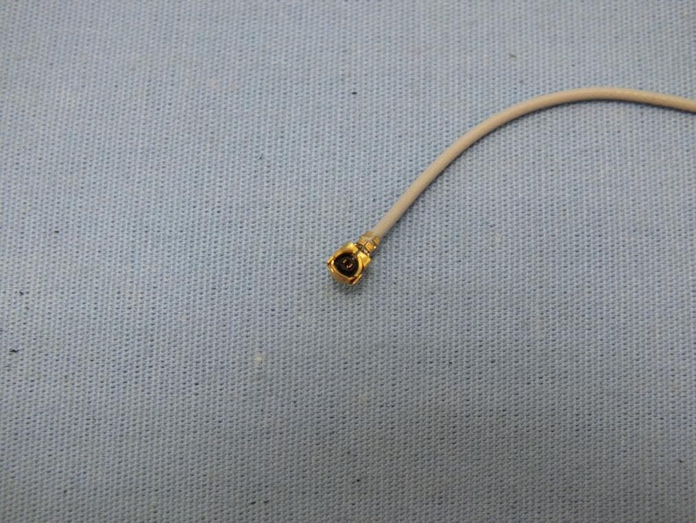
Click to zoom
Application Details
- Equipment Class
- NII - Unlicensed National Information Infrastructure TX
- Date of Grant
- Jul 22, 2014
- Application Purpose
- Original Equipment
- Date of Application
- Jul 21, 2014
- Equipment Note
- RGMII 802.11ac WLAN module
- Frequency Range
- 5180.00000000 - 5240.00000000
- Company
- Actiontec Electronics Inc
- Country
- United States
Documents & Files
Document Text
Text extracted from the exhibit documents filed with the FCC. Open a document above to read the original.
Users Manual
Federal Communication Commission Interference Statement This equipment has been tested and found to comply with the limits for a Class B digital device, pursuant to Part 15 of the FCC Rules. These limits are designed to provide reasonable protection against harmful interference in a residential installation. This equipment generates, uses and can radiate radio frequency energy and, if not installed and used in accordance with the instructions, may cause harmful interference to radio communications. However, there is no guarantee that interference will not occur in a particular installation. If this equipment does cause harmful interference to radio or television reception, which can be determined by turning the equipment off and on, the user is encouraged to try to correct the interference by one of the following measures: - Reorient or relocate the receiving antenna. - Increase the separation between the equipment and receiver. - Connect the equipment into an outlet on a circuit different from that to which the receiver is connected. - Consult the dealer or an experienced radio/TV technician for help. FCC Caution: Any changes or modifications not expressly approved by the party responsible for compliance could void the user's authority to operate this equipment. This device complies with Part 15 of the FCC Rules. Operation is subject to the following two conditions: (1) This device may not cause harmful interference, and (2) this device must accept any interference received, including interference that may cause undesired operation. IMPORTANT NOTE: Radiation Exposure Statement: The product comply with the US portable RF exposure limit set forth for an uncontrolled environment and are safe for intended operation as described in this manual. The further RF exposure reduction can be achieved if the product can be kept as far as possible from the user body or set the device to lower output power if such function is available. This transmitter must not be co-located or operating in conjunction with any other antenna or transmitter. Country Code selection feature to be disabled for products marketed to the US/CANADA This device is intended only for OEM integrators under the following conditions: 1) The transmitter module may not be co-located with any other transmitter or antenna, 2) For all products market in US, OEM has to limit the operation channels in CH1 to CH11 for 2.4G band by supplied firmware programming tool. OEM shall not supply any tool or info to the end-user regarding to Regulatory Domain change. As long as 2 conditions above are met, further transmitter test will not be required. However, the OEM integrator is still responsible for testing their end-product for any additional compliance requirements required with this module installed IMPORTANT NOTE In the event that these conditions can not be met (for example certain laptop configurations or co-location with another transmitter), then the FCC authorization is no longer considered valid and the FCC ID can not be used on the final product. In these circumstances, the OEM integrator will be responsible for re-evaluating the end product (including the transmitter) and obtaining a separate FCC authorization. End Product Labeling The final end product must be labeled in a visible area with the following: “Contains FCC ID: LNQRGM840”. Manual Information to the End User The OEM integrator has to be aware not to provide information to the end user regarding how to install or remove this RF module in the user’s manual of the end product which integrates this module. The end user manual shall include all required regulatory information/warning as show in this manual. Industry Canada statement: This device complies with Industry Canada licence-exempt RSS standard(s). Operation is subject to the following two conditions: (1) this device may not cause interference, and (2) this device must accept any interference, including interference that may cause undesired operation of the device. Le présent appareil est conforme aux CNR d'Industrie Canada applicables aux appareils radio exempts de licence. L'exploitation est autorisée aux deux conditions suivantes : (1) l'appareil ne doit pas produire de brouillage, et (2) l'utilisateur de l'appareil doit accepter tout brouillage radioélectrique subi, même si le brouillage est susceptible d'en compromettre le fonctionnement. Caution: (i) the device for operation in the band 5150-5250 MHz is only for indoor use to reduce the potential for harmful interference to co-channel mobile satellite systems; Avertissement: (i) les dispositifs fonctionnant dans la bande 5150-5250 MHz sont réservés uniquement pour une utilisation à l’intérieur afin de réduire les risques de brouillage préjudiciable aux systèmes de satellites mobiles utilisant les mêmes canaux; Radiation Exposure Statement: The product comply with the Canada portable RF exposure limit set forth for an uncontrolled environment and are safe for intended operation as described in this manual. The further RF exposure reduction can be achieved if the product can be kept as far as possible from the user body or set the device to lower output power if such function is available. Déclaration d'exposition aux radiations: Le produit est conforme aux limites d'exposition pour les appareils portables RF pour les Etats-Unis et le Canada établies pour un environnement non contrôlé. Le produit est sûr pour un fonctionnement tel que décrit dans ce manuel. La réduction aux expositions RF peut être augmentée si l'appareil peut être conservé aussi loin que possible du corps de l'utilisateur ou que le dispositif est réglé sur la puissance de sortie la plus faible si une telle fonction est disponible. This device is intended only for OEM integrators under the following conditions: 1) The transmitter module may not be co-located with any other transmitter or antenna. As long as 1 condition above are met, further transmitter test will not be required. However, the OEM …
Text truncated - open the document above for the full version.
Users Manual
Actiontec 11ac RGMII Module User’s Guide Part Number: RGM840 Revision 1.3 Date: 10/21/2013 Subject to change 1. Introduction This document provides the hardware specification for RGM840 module. This module supports 802.11ac standard with 5GHz 4x4 MIMO, 4 spatial streams, transmit beamforming and etc. This 11ac RGMII module uses local memory and flash to fully offload the host processor on the main board so only minimal software is required on the host for management purpose. 2. Block diagram The block diagram of the module is shown in figure 1. As indicated in the diagram, this module uses a proprietary RGMII over mPCIe interface and provides 4 U.FL antenna connectors for cable antenna. Figure 1. Block Diagram of the RGM840 module RGMII over mPCIe RGMII over mPCIe I/F DDR3 WPS Input WPS Input RGMI I RGMI I UART UART LEDs/ GPIOs/ HRST LEDs/ GPIOs/ HRST QT3840BC QT2518B FEM FFE M FEM FFE M FEM FFE M FEM FFE M U.FL U.FL 64KB Flash SPI0 3. General feature list Feature list Descriptions Target dimensions [mm] 80mm(L) x 60mm(W) Signaling connection RGMII connection over mPCIe connector Antenna connection 4 antenna connections via U.FL connectors . PCB 6 Layers Chipset QV840 (QT3840BC and QT2518B) RF FEM Microsemi LX5586H or Triquint TQP8080 (subject to change) Band support 5GHz Freq support 5180-5825MHz BW 20MHz/40MHz/80MHz Mixed mode Spatial Streams Up to 4SS Configuration and System management In-band or Web GUI WPS WPS input pin Wi-Fi LED Wi-Fi LED signal pin WPS LED WPS LED signal pin Radio ON/OFF Control Radio enable/disable pin Factory reset Factory reset to default input via mPCIe connector Hard reset Hardware reset input via mPCIe connector UART via mPCIe connector DDR3 Memory 16bit – 128MB, 400MHz SPI flash 64KB ( firmware downloaded via RGMII interface ) or 16MB Calibration data storage SPI flash Power Source via mPCIe connector, 3.3V-2.5A and optional 5V for FEM Interoperability Operates with 802.11a/n/ac clients/STA and AP MIMO features MU-MIMO, Tx Beamforming and LDPC Security WPA,WPA2 4. RF Specification Items Target Specification Total max conductive output power 24dBm with 3.3V TX EVM at antenna port (Subject to change for manufacturing) +17dBm @3% EVM, HT40, MCS7 +15dBm @1.8% EVM , MCS9 (subject to change) RX min. sensitivity (Subject to change for manufacturing) 20MHz MCS0 -93dBm 20MHz MCS7 -75dBm 40MHz MCS0 -90dBm 40MHz MSC7 -72dBm 80MHz MCS0 -87dBm 80MHz MCS7 -66dBm 80MHz MCS9 -60dBm Output power accuracy +/- 1.5 dB max 5. Pin assignment Pins Definitions Pin Type Pins Definitions Pin Type 1 5V 5V DC Input 2 5V 5V DC Input 3 5V 5V DC Input 4 5V 5V DC Input 5 GND Ground 6 GND Ground 7 EXTRST Reset Output 8 AGPIO_B_10 Bidirectional 9 GND Ground 10 AGPIO_B_11 Bidirectional 11 GMDIO_B Bidirectional 12 GMDC_O Output 13 GRXD_I_3 Input 14 WLAN_DISABLE (AGPIO_B_12) Input (0 : Disable) 15 GRXD_I_1 Input 16 GRXD_I_2 Input 17 GRXCLK_I Input 18 GRXD_I_0 Input 19 GND Ground 20 RXDV_I Input 21 GTXCLK_O Output 22 GND Ground 23 GND Ground 24 GTXCLK_I Input 25 GTXEN_O Output 26 GND Ground 27 GTXD_O_3 Output 28 GTXD_O_1 Output 29 GTXD_O_2 Output 30 GTXD_O_0 Output 31 GND Ground 32 RTD (Reset to Default) (AGPIO_B_5) Input 33 25M_GPHY Output 34 AGPIO_B_16 Bidirectional, PWM 35 GND Ground 36 AGPIO_B_6 Output 37 1_AGPIO_B_8 Output (UART TX) 38 WPS_LED2 (AGPIO_B_13) Output, PWM 39 WLAN_LED (AGPIO_B_1) Output, 3.3V, PWM 40 1_AGPIO_B_0 Input (UART RX) 41 WPS (AGPIO_B_4) Input (0: Active) 42 GND Ground 43 WPS_LED1 (AGPIO_B_3) Output, 3.3V, PWM 44 HRST Input (0 : Active) 45 GND Ground 46 GND Ground 47 3.3V 3.3V DC Input 48 3.3V 3.3V DC Input 49 3.3V 3.3V DC Input 50 3.3V 3.3V DC Input 51 3.3V 3.3V DC Input 52 3.3V 3.3V DC Input 6. Module power requirement Power supply: 3.3V DC input Max output power per chain = 18dBm (LX5586H or TQP8080) Voltage rails RMS Current rating (Max) 3.3V only 2.5A 7. Hardware reset (HRST) requirement Since the HRST signal is connected to the hard reset of QT3840BC and is also used to start the linux boot via RGMII interface, therefore it should be connected to the GPIO pin of the network processor so that it can be controlled by software. Once the HRST signal is deasserted, the module will start to request tftp server running on the host processor to fetch the bootloader and firmware image. The HRST should be keep low for no less than 30ms after the 3.3V supply reaches the nominal voltage. 8. Power Management Unit (PMU) The power management unit is a new feature integrated into the QT3840 chip and it consists of 3 switching regulators and 3 LDOs. The 3 buck converters are designed specifically to generate 1.1V for QT3840 core voltage, 1.2V for QT2518B, 1.5V for DDR3. The LDOs provide clean output voltages for oscillator, RF synthesizer and AFE block. In the latest revision of QTM840 RGMII module design, 1.1V for QT3840 core voltage is fed by external DC-DC switching regulator instead of PMU in the purpose of reducing the heat dissipation inside the QT3840 package. 3.3V HRST 3.3V IN 30ms QT3840BC PMU FEM 3.3V IN DC-DC SW 1.1V Core 1.2V RFIC4 1.5V DDR3 9. Mechanical drawing 10. Compliance Certifications 1. FCC EMI Certification – pending 2. FCC DFS Certification – pending 3. WiFi Certification - pending 60mm 80mm 11. RGMII interface connection example RGMII signals from the host processor RGMII signals from RGMII module pin assignments Signals Pin descriptions Pin Type Pin Signals Pin Type GTXD3 RGMII Transmit data bit 3 Output 13 GRXD_I_3 Input GTXD2 RGMII Transmit data bit 2 Output 16 GRXD_I_2 Input GTXD1 RGMII Transmit data bit 1 Output 15 GRXD_I_1 Input GTXD0 RGMII Transmit data bit 0 Output 18 GRXD_I_0 Input GTXEN RGMII Transmit enable Output 20 RXDV_I Input GTXCLK RGMII 125MHz TXCLK Output 17 GRXCLK_I Input GRXCLK RGMII receive clock Input 21 GTXCLK_O Output 1K Pull down resistor 24 GTXCLK_I Input GRXDV RGMII receive data valid Input 25 GTXEN_O Output GRXD3 RGMII Receive data bit 3 Output 27 GTXD_O_3 Output GRXD2 RGMII Receive data bit 2 Output 29 GTXD_O_2 Output GRXD1 R…
Text truncated - open the document above for the full version.
Cover Letter(s)
760 North Mary Avenue • Sunnyvale • CA • 94085 • USA Phone (408) 752-7700 • Fax (408) 541-9003 • www.actiontec.com Date: July 2, 2014 Federal Communications Commission 7435 Oakland Mills Rd Columbia MD 21046-1609 Subject: Product Certification Representative Authorization Letter FCC ID: LNQRGM840 Product name: RGMII 802.11ac WLAN module To whom it may concern: We the undersigned, hereby authorize following person to act as our agent in the preparation of an application for equipment authorization of model RGM840 to the FCC Rules and Regulations. International Certification Corp. Address : No.3-1, Lane 6, Wen San 3rd St. Kwei Shan Hsiang, Tao Yuan Hsein 333, Taiwan (R.O.C.) Name : Gary Chang Job Title : Manager e-mail : [email protected] We further certify that neither the applicant nor any party to this application, as defined in 47 CFR Ch. 1.2002(b), is subject to a denial to Federal benefits, including FCC benefits, pursuant to section 5301 of the Anti-Drug Abuse Act of 1998, 21 U.S.C. 835(a). This appointment also includes the authority to complete FCC Form 731 on our behalf and sign the application as an authorized agent. Sincerely, Angela Yao/Sr. Program Manager Phone: (408) 752-7700 Fax: (408) 541-9003 Email: [email protected] Solutions for the Digital Life™
Cover Letter(s)
760 North Mary Avenue • Sunnyvale • CA • 94085 • USA Phone (408) 752-7700 • Fax (408) 541-9003 • www.actiontec.com Confidentiality Request Letter Date: July 2, 2014 Federal Communications Commission Authorization and Evaluation Division FCC ID:LNQRGM840 Permanent Confidentiality Request Pursuant to Sections 0.457 and 0.459 of the Commission’s Rules, the Applicant Hereby requests confidential treatment of information accompanying this Application As outlined below: 1. Block Diagram 2. Circuit Diagram 3. Operational Description 4. Op-Software security The above materials contain trade secrets and proprietary information not customarily released to the public. The public disclosure of these matters might be harmful to the Applicant and provide unjustified benefits to its competitors. The Applicant understands that pursuant to Rule 0.457, disclosure of this Application and all accompanying documentation will not be made before the date of the Grant for this application Sincerely, Angela Yao/Sr. Program Manager Phone: (408) 752-7700 Fax: (408) 541-9003 Email: [email protected] Solutions for the Digital Life™
Cover Letter(s)
760 North Mary Avenue • Sunnyvale • CA • 94085 • USA Phone (408) 752-7700 • Fax (408) 541-9003 • www.actiontec.com Date: July 2, 2014 Subject: Ad Hoc Mode Function Declaration FCC ID: LNQRGM840 IC ID: 2496A-RGM840 To whom it may concern, We, Actiontec Electronics, Inc. declare that the device does not support any non-US channels and country code selection in all the operational mode(s) for the following product. Sincerely, Angela Yao/Sr. Program Manager Phone: (408) 752-7700 Fax: (408) 541-9003 Email: [email protected] Solutions for the Digital Life™
Cover Letter(s)
RF_734_00, Issue 1 Modular Approval Request FCC (per DA 00-1407) FCC ID: LNQRGM840 Items to be covered Answer from applicant 1. The modular transmitter must have its own RF shielding. The modular has a shielding Case. Please refer to EUT Photo. 2. The modular transmitter must have buffered modulation/data inputs (if such inputs are provided) to ensure that the module will comply with Part 15 requirements under conditions of excessive data rates or over-modulation. The component number is QT3840 3. The modular transmitter must have its own power supply regulation. The component number is MP2161GJ 4. The modular transmitter must comply with the antenna requirements of Section 15.203 and 15.204(c). The antenna must either be permanently attached or employ a “unique” antenna coupler (at all connections between the module and the antenna, including the cable).. The device has UFL antenna Connector. And no external amplifier will be used with this modular. 5. The modular transmitter must be tested in a stand-alone configuration, i.e., the module must not be inside another device during testing. This is intended to demonstrate that the module is capable of complying with Part 15 emission limits regardless of the device into which it is eventually installed. This modular is tested under stand-alone configuration. Please refer to Test setup photo. 6. The modular transmitter must be labeled with its own FCC ID number, and, if the FCC ID is not visible when the module is installed inside another device, then the outside of the device into which the module is installed must also display a label referring to the enclosed module. This exterior label can use wording such as the following: “Contains Transmitter Module FCC ID: XYZMODEL1” or “Contains FCC ID: XYZMODEL1.” Any similar wording that expresses the same meaning may be used. The Grantee may either provide such a label, an example of which must be included in the application for equipment authorization, or, must provide adequate instructions along with the module which explain this requirement. In the latter case, a copy of these instructions must be included in the application for equipment authorization. The modular transmitter is labeled with its own FCC ID number. Please refer to label sample and label location. 7. The modular transmitter must comply with any specific rule or operating requirements applicable to the transmitter and the manufacturer must provide adequate instructions along with the module to explain any such requirements. A copy of these instructions must be included in the application for equipment authorization. For example, there are very strict operational and timing requirements that must be met before a transmitter is authorized for operation under Section 15.231. For instance, data transmission is prohibited, except for operation under Section 15.231(e), in which case there are separate field strength level and timing requirements. Compliance with these requirements must be assured. The modular complies with this requirement. Please refer to user manual. 8. The modular transmitter must comply with any applicable RF exposure requirements. For example, FCC Rules in Sections 2.1091, 2.1093 and specific Sections of Part 15, including 15.319(i), 15.407(f), 15.253(f) and 15.255(g), require that Unlicensed PCS, UNII and millimeter wave devices perform routine environmental evaluation for RF Exposure to demonstrate compliance. In addition, spread spectrum transmitters operating under Section 15.247 are required to address RF Exposure compliance in accordance with Section 15.247(b)(4). Modular transmitters approved under other Sections of Part 15, when necessary, may also need to address certain RF Exposure concerns, typically by providing specific installation and operating instructions for users, installers and other interested parties to ensure compliance. The device complies with this requirement. Please refer to RF exposure report. Note: If compliance with one or more of the numbered requirements, listed above, cannot be demonstrated, it may be possible to obtain a “Limited Modular Approval” (LMA). Name and surname of applicant (or authorized representative): __________________ Date: ___17 July 2014____ Signature: ___________________________
External Photos
Project No.: EP452903 Page No. : 1 of 8 Photographs of EUT Project No.: EP452903 Page No. : 2 of 8 Project No.: EP452903 Page No. : 3 of 8
ID Label/Location Info
3mm 26mm (W) x 11mm (H) Label location
Internal Photos
Project No.: EP452903 Page No. : 4 of 8 Project No.: EP452903 Page No. : 5 of 8 Project No.: EP452903 Page No. : 6 of 8 Project No.: EP452903 Page No. : 7 of 8 Project No.: EP452903 Page No. : 8 of 8
RF Exposure Info
Report No.: FA452903 Page : 1 of 6 Report Version: Rev. 01 FCC RF Exposure Report FCC ID : LNQRGM840 Equipment : RGMII 802.11ac WLAN module Model No. : RGM840 Brand Name : Actiontec Applicant : Actiontec Electronics, Inc. Address : 760 North Mary Ave. Sunnyvale, CA 94085 Standard : 47 CFR FCC Part 2.1091 Received Date : May 29, 2014 Tested Date : Jun. 03 ~ Jun. 30, 2014 We, International Certification Corp., would like to declare that the tested sample has been evaluated and in compliance with the requirement of the above standards. The test results contained in this report refer exclusively to the product. It may be duplicated completely for legal use with the approval of the applicant. It shall not be reproduced except in full without the written approval of our laboratory. Approved & Reviewed by: Gary Chang / Manager Ty: XXX Report No.: FA452903 Page : 2 of 6 Report Version: Rev. 01 Table of Contents 1 MPE EVALUATION OF MOBILE DEVICES ......................................................................................... 4 1.1 LIMITS FOR GENERAL POPULATION/UNCONTROLLED EXPOSURE............................................. 4 1.2 MPE EVALUATION FORMULA ............................................................................................................. 4 1.3 MPE EVALUATION RESULTS .............................................................................................................. 5 2 TEST LABORATORY INFORMATION ................................................................................................. 6 Report No.: FA452903 Page : 3 of 6 Report Version: Rev. 01 Release Record Report No. Version Description Issued Date FA452903 Rev. 01 Initial issue Jul. 11, 2014 Report No.: FA452903 Page : 4 of 6 Report Version: Rev. 01 1 MPE EVALUATION OF MOBILE DEVICES Human exposure to RF emissions from mobile devices (47 CFR §2.1091) may be evaluated based on the MPE limits adopted by the FCC for electric and magnetic field strength and/or power density, as appropriate, since exposures are assumed to occur at distances of 20 cm or more from persons. 1.1 LIMITS FOR GENERAL POPULATION/UNCONTROLLED EXPOSURE Frequency Range (MHz) Power Density (mW /cm 2 ) Averaging Time (minutes) 300~1500 F/1500 30 1500~100000 1.0 30 1.2 MPE EVALUATION FORMULA Pd = 2 **4RPi Pt Where Pd= Power density in mW/cm 2 Pt= EIRP in mW Pi= 3.1416 R= Measurement distance Report No.: FA452903 Page : 5 of 6 Report Version: Rev. 01 1.3 MPE EVALUATION RESULTS Legacy/MIMO (CDD) Non-beamforming mode Frequency Range (MHz) Maximum Conducted Power (dBm) Antenna Gain (dBi) Distance (cm) Power Density (mW/cm 2 ) Limit (mW/cm 2 ) 5150-5250 25.51 0.99 20 0.089 1 5725-5850 25.22 0.21 20 0.069 1 Legacy/MIMO (CDD) beamforming mode Frequency Range (MHz) Maximum Conducted Power (dBm) Antenna Gain (dBi) Distance (cm) Power Density (mW/cm 2 ) Limit (mW/cm 2 ) 5150-5250 25.11 7.01 20 0.324 1 5725-5850 25.29 6.23 20 0.282 1 Report No.: FA452903 Page : 6 of 6 Report Version: Rev. 01 2 Test laboratory information Established in 2012, ICC provides foremost EMC & RF Testing and advisory consultation services by our skilled engineers and technicians. Our services employ a wide variety of advanced edge test equipment and one of the widest certification extents in the business. International Certification Corp, it is our definitive objective is to institute long term, trust-based associations with our clients. The expectation we set up with our clients is based on outstanding service, practical expertise and devotion to a certified value structure. Our passion is to grant our clients with best EMC / RF services by oriented knowledgeable and accommodating staff. Our Test sites are located at Linkou District and Kwei Shan Hsiang. Location map can be found on our website http://www.icertifi.com.tw. Linkou Kwei Shan Kwei Shan Site II Tel: 886-2-2601-1640 Tel: 886-3-271-8666 Tel: 886-3-271-8640 No. 30-2, Ding Fwu Tsuen, Lin Kou District, New Taipei City, Taiwan, R.O.C. No. 3-1, Lane 6, Wen San 3rd St., Kwei Shan Hsiang, Tao Yuan Hsien 333, Taiwan, R.O.C. No. 14-1, Lane 19, Wen San 3rd St., Kwei Shan Hsiang, Tao Yuan Hsien 333, Taiwan, R.O.C. If you have any suggestion, please feel free to contact us as below information Tel: 886-3-271-8666 Fax: 886-3-318-0155 Email: [email protected] ══END══
Test Report
Report No.: FR452903 Page : 1 of 111 Report Version: Rev. 02 FCC Test Report FCC ID : LNQRGM840 Equipment : RGMII 802.11ac WLAN module Model No. : RGM840 Brand Name : Actiontec Applicant : Actiontec Electronics, Inc. Address : 760 North Mary Ave. Sunnyvale, CA 94085 Standard : 47 CFR FCC Part 15.407 Received Date : May 29, 2014 Tested Date : Jun. 03 ~ Jun. 30, 2014 We, International Certification Corp., would like to declare that the tested sample has been evaluated and in compliance with the requirement of the above standards. The test results contained in this report refer exclusively to the product. It may be duplicated completely for legal use with the approval of the applicant. It shall not be reproduced except in full without the written approval of our laboratory. Approved & Reviewed by: Gary Chang / Manager Ty: XXX Report No.: FR452903 Page : 2 of 111 Report Version: Rev. 02 Table of Contents 1 GENERAL DESCRIPTION .................................................................................................................... 5 1.1 Information .............................................................................................................................................. 5 1.2 Local Support Equipment List ................................................................................................................ 8 1.3 Test Setup Chart .................................................................................................................................... 8 1.4 The Equipment List .............................................................................................................................. 10 1.5 Testing Applied Standards ................................................................................................................... 11 1.6 Measurement Uncertainty .................................................................................................................... 11 2 TEST CONFIGURATION ..................................................................................................................... 12 2.1 Testing Condition ................................................................................................................................. 12 2.2 The Worst Test Modes and Channel Details ....................................................................................... 13 3 TRANSMITTER TEST RESULTS ........................................................................................................ 15 3.1 Conducted Emissions ........................................................................................................................... 15 3.2 Emission Bandwidth ............................................................................................................................. 24 3.3 RF Output Power .................................................................................................................................. 29 3.4 Peak Power Spectral Density ............................................................................................................... 32 3.5 Transmitter Radiated and Band Edge Emissions ................................................................................ 38 3.6 Frequency Stability ............................................................................................................................. 109 4 TEST LABORATORY INFORMATION ............................................................................................. 111 Report No.: FR452903 Page : 3 of 111 Report Version: Rev. 02 Release Record Report No. Version Description Issued Date FR452903 Rev. 01 Initial issue Jul. 11, 2014 FR452903 Rev. 02 Revised frequency range on page 7. Jul. 22, 2014 Report No.: FR452903 Page : 4 of 111 Report Version: Rev. 02 Summary of Test Results FCC Rules Test Items Measured Result 15.207 Conducted Emissions [dBuV]: 0.177MHz 60.04 (Margin -4.60dB) - QP Pass 15.407(b) 15.209 Radiated Emissions [dBuV/m at 3m]: 5150.00MHz 53.88 (Margin -0.12dB) - AV Pass 15.407(a) Emission Bandwidth Meet the requirement of limit Pass 15.407(e) 6dB bandwidth Meet the requirement of limit Pass 15.407(a) RF Output Power Max Power [dBm]: Non-beamforming mode 5150-5250MHz: 25.51 5725-5850MHz: 25.22 Beamforming mode 5150-5250MHz: 25.11 5725-5850MHz: 25.29 Pass 15.407(a) Peak Power Spectral Density Meet the requirement of limit Pass 15.407(g) Frequency Stability Meet the requirement of limit Pass 15.203 Antenna Requirement Meet the requirement of limit Pass Report No.: FR452903 Page : 5 of 111 Report Version: Rev. 02 1 General Description 1.1 Information 1.1.1 Specification of the Equipment under Test (EUT) RF General Information IEEE Std. 802.11 Frequency Range (MHz) Ch. Freq. (MHz) Channel Number Transmit Chains (N TX ) Data Rate / MCS a 5150-5250 5180-5240 36-48 [4] 4 6-54 Mbps n (HT20) 5150-5250 5180-5240 36-48 [4] 4 MCS 0-31 n (HT40) 5150-5250 5190-5230 38-46 [2] 4 MCS 0-31 ac (VHT20) 5150-5250 5180-5240 36-48 [4] 4 MCS 0-9 ac (VHT40) 5150-5250 5190-5230 38-46 [2] 4 MCS 0-9 ac (VHT80) 5150-5250 5210 42 [1] 4 MCS 0-9 Note 1: RF output power specifies that Maximum Conducted Output Power. Note 2: 802.11a/n/ac uses a combination of OFDM-BPSK, QPSK, 16QAM, 64QAM, 256QAM modulation. Note 3: 802.11n/ac supports MIMO CDD function with beamforming. RF General Information IEEE Std. 802.11 Frequency Range (MHz) Ch. Freq. (MHz) Channel Number Transmit Chains (N TX ) Data Rate / MCS a 5725-5850 5745-5825 149-165 [5] 4 6-54 Mbps n (HT20) 5725-5850 5745-5825 149-165 [5] 4 MCS 0-31 n (HT40) 5725-5850 5755-5795 151-159 [2] 4 MCS 0-31 ac (VHT20) 5725-5850 5745-5825 149-165 [5] 4 MCS 0-9 ac (VHT40) 5725-5850 5755-5795 151-159 [2] 4 MCS 0-9 ac (VHT80) 5725-5850 5775 155 [1] 4 MCS 0-9 Note 1: RF output power specifies that Maximum Conducted Output Power. Note 2: 802.11a/n/ac uses a combination of OFDM-BPSK, QPSK, 16QAM, 64QAM, 256QAM modulation. Note 3: 802.11n/ac supports M…
Text truncated - open the document above for the full version.
Test Setup Photos
Report No.: FR452903 Page: : 1 of 4 Repo…
Text truncated - open the document above for the full version.
Contact Information
Applicant
Zhe Liu(Product Manager)
Technical Contact
International Certification Corp.Gary Chang
886-3-271-8628
Taiwan
Non-Technical Contact
International Certification Corp.Wendy Liao
886-3-271-8629
Test Firm
International Certification Corp.Fu-Cheng Chuang
Technical Specifications
| # | Rule Parts | Frequency Range | Power Output |
|---|---|---|---|
| 2 | 15E | 5.18 GHz - 5.24 GHz | 356.00 mW |
Other Applications from Actiontec Electronics Inc

LNQWF672
Dec 26, 2025Wi-Fi 7 Outdoor Mesh AP
Equipment Class
DTS - Digital Transmission System
LNQ-WF670G
Dec 09, 2025Wi-Fi 7 Outdoor Mesh AP
Equipment Class
DTS - Digital Transmission SystemLNQ-WF815-2
Apr 14, 2024Tri-band Wi-Fi 6E Wireless AP
Equipment Class
DTS - Digital Transmission System
LNQ-WF825
Mar 24, 2024Tri-band Wi-Fi 7 Wireless AP
Equipment Class
6ID - 15E 6 GHz Low Power Indoor Access Point
LNQ-WF810G-2
Mar 23, 2024Wi-Fi 6E Mesh Extender
Equipment Class
DTS - Digital Transmission System