LNQSG200Gateway Device with 802.11n and Z-Wave Home Control
Actiontec Electronics Inc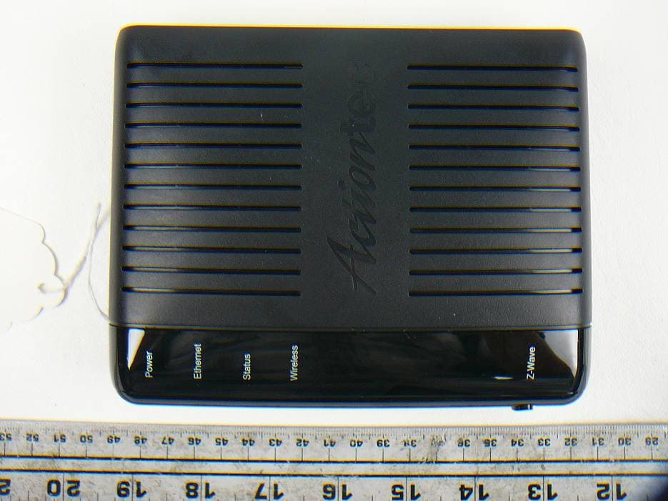
Click to zoom
Application Details
- Equipment Class
- DXX - Part 15 Low Power Communication Device Transmitter
- Date of Grant
- Apr 28, 2011
- Application Purpose
- Original Equipment
- Date of Application
- Apr 28, 2011
- Equipment Note
- Gateway Device with 802.11n and Z-Wave Home Control
- Frequency Range
- 908.40000000 - 908.40000000
- Company
- Actiontec Electronics Inc
- Country
- United States
Documents & Files
Document Text
Text extracted from the exhibit documents filed with the FCC. Open a document above to read the original.
Users Manual
1 Actiontec Electronics, Inc. 760 North Mary Ave., Sunnyvale, CA 94085 USA Gateway Device with 802.11n and Z‐Wave Home Control Model #: SG200 and SG200 Rev. B Quick Start Guide Version: 0.0 (Draft to be review) 2 Connect the SG200/SG200 Rev. B Gateway to Power and Router 1. Plug one end of the Ethernet cable to the Ethernet port on the SG200/SG200 Rev. B gateway. 2. Plug the other end of the Ethernet cable into the LAN port on the back of your router. 3. Plug the AC power adapter connector to the SG200/SG200 Rev. B gateway’s power port. (Power: External, 10V DC, 1.6A made by Adapter Technology Co., Ltd.; Model: STD‐10016U) 4. Now plug the power adapter into a properly grounded power outlet. 5. Make sure the power LED light on the Gateway device is green. 6. Your Ethernet LED light is green if the Ethernet cable is connected. Connect the SG200/SG200 Rev. B to Router Wirelessly (Optional) 1. Find out the IP address of the SG200/SG200 Rev. B Gateway. Usually you can do this by looking up the DHCP client list from the router’s webpage. Let’s assume it is 192.168.1.2. 2. Using a computer with a SSH client, connect to the SG200/SG200 Rev. B Gateway. a. For Windows computers, Putty is a good SSH client program. Configure Putty using its GUI and enter the IP address as 192.168.1.2 and port 22, then hit the connect button. b. For Linux computers, open a terminal and enter “ssh [email protected]”. 3. If prompted for username, enter “root”. There is no password. 4. Create a configuration file. Type this command vi /config/wpa_supplicant.conf Enter the following information inside the vi text editor. Enter “i” to start the editing mode. network={ ssid="Your_Access_Point's_SSID" psk="Your_WPA_or_WPA2_Passphrase" } Press “ESC” to exit the editing mode. Save the file by typing “:wq!”. 5. Now connect to the router. Type the command wpa_supplicant –Dwext –iwlan0 –c/config/wpa_supplicant.conf –B 6. Get an IP from the router. Type the command dhclient wlan0 If you see a message similar to “bound to 192.168.1.3 ‐‐ renewal in 35739 seconds.” that means you are successfully connected. Note this instruction works with WPA or WPA2 encrypted wireless networks only. Congratulations you are now connected! 3 Specifications 1. Features • Compliant with IEEE 802.3 Ethernet standard. • Supports 100BaseT and 1000BaseT. • 2.4 GHz IEEE 802.11n Draft‐compliant • 2‐stream spatial multiplexing up to 135 Mbps • Supports 20 MHz channels • Full IEEE 802.11 b/g/n legacy compatibility with enhanced performance • Comprehensive wireless network security support that includes WPA, WPA2, and AES encryption/decryption coupled with TKIP and IEEE 802.1X support • 802.11b Data Rates: 11Mbit/s, 5.5Mbit/s, 2Mbit/s, 1Mbit/s (And 22Mbit/s with PBCC); • 802.11g Data Rates: 6Mbit/s, 9Mbit/s, 12Mbit/s, 18Mbit/s, 24Mbit/s, 36Mbit/s, 48Mbit/s, 54Mbit/s. 2. Power requirements • Operating voltage: +10V DC @ 1.6A max 3. Environmental Operating Range • Operating temperature: 0º C to 40º C (32º F to 104º F) • Humidity: 5‐95%, non‐condensing 4. Dimension and Weight • 7” (L) x 5.5” (W) x 1.5” (H) 0.65 lb. 5. Certifications • FCC Part 15 Class B and Class C; UL GeneralRegulatoryandComplianceNotices ImportantSafetyInstructions Ifapplicable,whenusingtelephoneequipment,basicsafetyprecautionsshouldalwaysbefollowedtoreducetheriskoffire,electrical shock,andpersonalinjury,includingthefollowing: • Donotusethisproductnearwater–forexample,nearabathtub,kitchensink,laundrytub,orswimmingpool,orinawetbasement; • Avoidusingatelephone(otherthanacordlesstype)duringanelectricalstorm,astheremaybearemoteriskofelectricalshock duetolightning; • Donotusethetelephonetoreportagasleakinthevicinityoftheleak; • Useonlythepowercordandbatteriesindicatedinthismanual; • Donotdisposeofbatteriesinfire,astheymayexplode–checkwithlocalcodesforpossiblespecialdisposalinstructions. TelephoneLineCordCaution Toreducetheriskoffire,useonlyNo.26AWGorlarger(e.g.,24AWG)ULListedorCSACertifiedTelecommunicationLineCord. CoaxialCable Ifapplicable,thecoaxialcablescreenshieldneedstobeconnectedtotheEarthatthebuildingentranceperANSI/NFPA70,theNationalElectrical Code(NEC),inparticularSection82093,“GroundingofOuterConductiveShieldofaCoaxialCable,”orinaccordancewithlocalregulation. FCCClassBEquipment ThisequipmenthasbeentestedandfoundtocomplywiththelimitsforaClassBdigitaldevice,pursuanttoPart15oftheFCCRules.These limitsaredesignedtoprovidereasonableprotectionagainstharmfulinterferenceinaresidentialinstallation.Thisequipmentgenerates, usesandcanradiateradiofrequencyenergyand,ifnotinstalledandusedinaccordancewiththeinstructions,maycauseharmful interferencetoradiocommunications.However,thereisnoguaranteethatinterferencewillnotoccurinaparticularinstallation.Ifthis equipmentdoescauseharmfulinterferencetoradioortelevisionreception,whichcanbedeterminedbyturningtheequipmentoffand on,theuserisencouragedtotryandcorrecttheinterferencebyimplementingoneormoreofthefollowingmeasures: • Reorientorrelocatethereceivingantenna; • Increasetheseparationbetweentheequipmentandreceiver; • Connecttheequipmenttoanoutletonacircuitdifferentfromthattowhichthereceiverisconnected; • Consultthedealeroranexperienceradioortelevisiontechnicianforhelp. Modifications TheFCCrequirestheusertobenotifiedthatanychangesormodificationsmadetothisdevicethatarenotexpresslyapprovedby ActiontecElectronics,Inc,mayvoidtheuser’sauthoritytooperatetheequipment. DeclarationofconformityforproductsmarkedwiththeFCClogo–UnitedStatesonly. ThisdevicescomplieswithPart15oftheFCCRules.Operationissubjecttothefollowingtwoconditions: 1.Thisdevicemaynotcauseharmfulinterference; 2.Thisdevicemustacceptanyinterferencereceived,includinginterferencethatmaycauseunwantedoperation. ImportantNote Ifapplicable,thisequipmentcomplieswithFCCradiationexposurelimitssetforthforanuncontrolledenvironment.Thisequipment shouldbeinstalledandoperatedwithminimumdistance20cmbetweentheradiatorandyourbody. Thetransmittermustnotbeco-locatedoroperatinginconjunctionwithanyotherantennaortransmitter. Forques…
Text truncated - open the document above for the full version.
External Photos
Actiontec Electronic, Inc. FCC ID: LNQSG200 Report No.: R1103282-249 Page 25 of 28 FCC Part 15.249 Test Report 9 Exhibit C - EUT Photographs 9.1 EUT – Top View 9.2 EUT-Bottom View Actiontec Electronic, Inc. FCC ID: LNQSG200 Report No.: R1103282-249 Page 26 of 28 FCC Part 15.249 Test Report 9.3 EUT-Port View 9.4 EUT – Power Adapter View
ID Label/Location Info
Actiontec Electronic, Inc. FCC ID: LNQSG200 Report No.: R1103282-249 Page 20 of 28 FCC Part 15.249 Test Report 7 Exhibit A – FCC Equipment Labeling Requirements 7.1 FCC ID Label Requirements As per FCC §2.925, (a) Each equipment covered in an application for equipment authorization shall bear a nameplate or label listing the following: (1) FCC Identifier consisting of the two elements in the exact order specified in §2.926. The FCC Identifier shall be preceded by the term FCC ID in capital letters on a single line, and shall be of a type size large enough to be legible without the aid of magnification. Example: FCC ID: XXX123 Where: XXX—Grantee Code, 123—Equipment Product Code As per FCC §15.19, (a) In addition to the requirements in part 2 of this chapter, a device subject to certification, or verification shall be labeled as follows: (3) All other devices shall bear the following statement in a conspicuous location on the device: This device complies with part 15 of the FCC Rules. Operation is subject to the following two conditions: (1) This device may not cause harmful interference, and (2) this device must accept any interference received, including interference that may cause undesired operation. (4) Where a device is constructed in two or more sections connected by wires and marketed together, the statement specified above is required to be affixed only to the main control unit. If the EUT is integrated within another device then a label affixed to the host shall also state, “Contains FCC ID: XXXXXX” (5) When the device is so small or for such use that it is not practicable to place the statement specified under paragraph (a) of this section on it, the information required by this paragraph shall be placed in a prominent location in the instruction manual or pamphlet supplied to the user or, alternatively, shall be placed on the container in which the device is marketed. However, the FCC identifier or the unique identifier, as appropriate, must be displayed on the device. 7.2 FCC ID Label Contents Actiontec Electronic, Inc. FCC ID: LNQSG200 Report No.: R1103282-249 Page 21 of 28 FCC Part 15.249 Test Report 7.3 FCC ID Label Location
Internal Photos
Actiontec Electronic, Inc. FCC ID: LNQSG200 Report No.: R1103282-249 Page 27 of 28 FCC Part 15.249 Test Report 9.5 EUT PCB Board – Top View 9.6 EUT PCB Board – Bottom View Actiontec Electronic, Inc. FCC ID: LNQSG200 Report No.: R1103282-249 Page 28 of 28 FCC Part 15.249 Test Report 9.7 EUT – Antenna View ***** END OF REPORT ***** WLAN Antenna Z-Wave Antenna
Test Report
Note: This test report is prepared for the customer shown above and for the device described herein. It may not be duplicated or used in part without prior written consent from Bay Area Compliance Laboratories Corp. This report must not be used by the customer to claim product certification, approval, or endorsement by NVLAP*, NIST, or any agency of the Federal Government. * This report may contain data that are not covered by the NVLAP accreditation and are marked with an asterisk “*” (Rev.2) FCC PART 15.249 TEST AND MEASUREMENT REPORT For Actiontec Electronics, Inc. 760 North Mary Ave., Sunnyvale, CA 94085, USA FCC ID: LNQSG200 Report Type: Original Report Product Type: Gateway Device with 802.11b/g/n and Z-Wave Home Control Test Engineers: Jerry Huang Report Number: R1103282-249 Report Date: 2011-04-27 Reviewed By: Victor Zhang RF Lead Prepared By: (84) Bay Area Compliance Laboratories Corp. 1274 Anvilwood Avenue, Sunnyvale, CA 94089, USA Tel: (408) 732-9162 Fax: (408) 732-9164 Actiontec Electronic, Inc. FCC ID: LNQSG200 Report No.: R1103282-249 Page 2 of 28 FCC Part 15.249 Test Report TABLE OF CONTENTS 1 GENERAL INFORMATION ..................................................................................................................................... 5 1.1 PRODUCT DESCRIPTION FOR EQUIPMENT UNDER TEST (EUT) ................................................................................. 5 1.2 MECHANICAL DESCRIPTION OF EUT........................................................................................................................ 5 1.3 OBJECTIVE............................................................................................................................................................... 5 1.4 RELATED SUBMITTAL(S)/GRANT(S) ......................................................................................................................... 5 1.5 TEST METHODOLOGY............................................................................................................................................... 5 1.6 MEASUREMENT UNCERTAINTY................................................................................................................................5 1.7 TEST FACILITY......................................................................................................................................................... 6 2 SYSTEM TEST CONFIGURATION ........................................................................................................................ 7 2.1 JUSTIFICATION......................................................................................................................................................... 7 2.2 EUT EXERCISE SOFTWARE...................................................................................................................................... 7 2.3 EQUIPMENT MODIFICATIONS................................................................................................................................... 7 2.4 LOCAL SUPPORT EQUIPMENT................................................................................................................................... 7 2.5 POWER SUPPLY AND LINE FILTERS.......................................................................................................................... 7 2.6 INTERFACE PORTS AND CABLING............................................................................................................................. 7 2.7 INTERNAL CONFIGURATION..................................................................................................................................... 7 3 SUMMARY OF TEST RESULTS ............................................................................................................................. 8 4 FCC §15.203 – ANTENNA REQUIREMENTS ........................................................................................................ 9 4.1 APPLICABLE STANDARD........................................................................................................................................... 9 4.2 ANTENNA CONNECTOR CONSTRUCTION.................................................................................................................. 9 5 FCC §15.207 – AC LINE CONDUCTED EMISSIONS ........................................................................................... 10 5.1 APPLICABLE STANDARD......................................................................................................................................... 10 5.2 TEST SETUP............................................................................................................................................................ 10 5.3 TEST PROCEDURE................................................................................................................................................... 10 5.4 TEST EQUIPMENT LIST AND DETAILS..................................................................................................................... 10 5.5 TEST SETUP BLOCK DIAGRAMS............................................................................................................................. 11 5.6 TEST ENVIRONMENTAL CONDITIONS..................................................................................................................... 11 5.7 TEST RESULTS........................................................................................................................................................ 11 5.8 CONDUCTED EMISSION DATA & PLOTS................................................................................................................. 12 6 FCC §15.205, §15.209 & §15.249 - RADIATED EMISSIONS................................................................................. 14 6.1 APPLICABLE STANDARD..............................................................................................…
Text truncated - open the document above for the full version.
Test Setup Photos
Actiontec Electronic, Inc. FCC ID: LNQSG200 Report No.: R1103282-249 Page 22 of 28 FCC Part 15.249 Test Report 8 Exhibit B - Test Setup Photographs 8.1 Radiated Emission below 1 GHz Front View @ 3 Meter 8.2 Radiated Emission below 1 GHz Rear View @ 3 Meter Actiontec Electronic, Inc. FCC ID: LNQSG200 Report No.: R1103282-249 Page 23 of 28 FCC Part 15.249 Test Report 8.3 Radiated Emission above 1 GHz Front View @ 3 Meter 8.4 Radiated Emission above 1 GHz Front View @ 3 Meter Actiontec Electronic, Inc. FCC ID: LNQSG200 Report No.: R1103282-249 Page 24 of 28 FCC Part 15.249 Test Report 8.5 AC Line Conducted Emission Front View 8.6 AC Line Conducted Emission Side View
Contact Information
Applicant
Brian Henrichs(President)
Test Firm
Bay Area Compliance LaboratoryJohn Chan
Technical Specifications
| # | Rule Parts | Frequency Range | Power Output |
|---|---|---|---|
| 1 | 15C | 908.4 MHz - 908.4 MHz | - |
Other Applications from Actiontec Electronics Inc

LNQWF672
Dec 26, 2025Wi-Fi 7 Outdoor Mesh AP
Equipment Class
DTS - Digital Transmission System
LNQ-WF670G
Dec 09, 2025Wi-Fi 7 Outdoor Mesh AP
Equipment Class
DTS - Digital Transmission SystemLNQ-WF815-2
Apr 14, 2024Tri-band Wi-Fi 6E Wireless AP
Equipment Class
DTS - Digital Transmission System
LNQ-WF825
Mar 24, 2024Tri-band Wi-Fi 7 Wireless AP
Equipment Class
6ID - 15E 6 GHz Low Power Indoor Access Point
LNQ-WF810G-2
Mar 23, 2024Wi-Fi 6E Mesh Extender
Equipment Class
DTS - Digital Transmission System