LNQWCB3000Wireless Coax Network Adapter
Actiontec Electronics Inc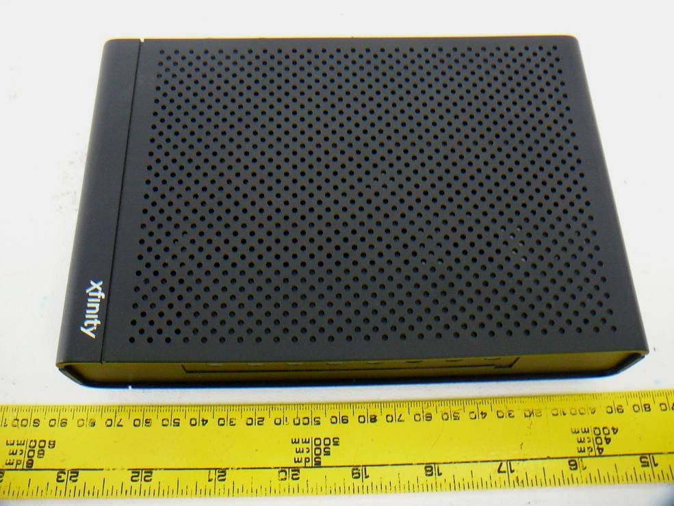
Click to zoom
Application Details
- Equipment Class
- NII - Unlicensed National Information Infrastructure TX
- Date of Grant
- Feb 03, 2013
- Application Purpose
- Original Equipment
- Date of Application
- Feb 03, 2013
- Equipment Note
- Wireless Coax Network Adapter
- Frequency Range
- 5190.00000000 - 5230.00000000
- Company
- Actiontec Electronics Inc
- Country
- United States
Documents & Files
Document Text
Text extracted from the exhibit documents filed with the FCC. Open a document above to read the original.
Users Manual
General Regulatory and Compliance Notices Important Safety Instructions If applicable, when using telephone equipment, basic safety precautions should always be followed to reduce the risk of fire, electrical shock, and personal injury, including the following: • Do not use this product near water –for example, near a bathtub, kitchen sink, laundry tub, or swimming pool, or in a wet basement; • Avoid using a telephone (other than a cordless type) during an electrical storm, as there may be a remote risk of electrical shock due to lightning; • Do not use the telephone to report a gas leak in the vicinity of the leak; • Use only the power cord and batteries indicated in this manual; • Do not dispose of batteries in fire, as they may explode –check with local codes for possible special disposal instructions. Telephone Line Cord Caution To reduce the risk of fire, use only No. 26 AWG or larger (e.g., 24 AWG) UL Listed or CSA Certified Telecommunication Line Cord. Coaxial Cable If applicable, the coaxial cable screen shield needs to be connected to the Earth at the building entrance per ANSI/NFPA 70, the National Electrical Code (NEC), in particular Section 820.93, “Grounding of Outer Conductive Shield of a Coaxial Cable,” or in accordance with local regulation. For Audio/Video Apparatus This reminder is provided to call the CATV system installer's attention to Section 820.93 of the National Electric Code (NEC), which provides guidelines for proper grounding and, in particular, specifies that the coaxial cable shield shall be connected to the grounding system of the building, as close to the point of cable entry as practical. Please heed all warnings; read, keep and follow all instructions. Do not use this apparatus near water and only clean with dry cloth. Do not block any ventilation openings. Install in accordance with the manufacturer's instructions. Do not install near any heat sources such as radiators, heat registers, stoves, or other apparatus including amplifiers that produce heat. FCC Class B Equipment This equipment has been tested and found to comply with the limits for a Class B digital device, pursuant to Part 15 of the FCC Rules. These limits are designed to provide reasonable protection against harmful interference in a residential installation. This equipment generates, uses and can radiate radio frequency energy and, if not installed and used in accordance with the instructions, may cause harmful interference to radio communications. However, there is no guarantee that interference will not occur in a particular installation. If this equipment does cause harmful interference to radio or television reception, which can be determined by turning the equipment off and on, the user is encouraged to try and correct the interference by implementing one or more of the following measures: • Reorient or relocate the receiving antenna; • Increase the separation between the equipment and receiver; • Connect the equipment to an outlet on a circuit different from that to which the receiver is connected; • Consult the dealer or an experience radio or television technician for help. Modifications T he FCC requires the user to be notified that any changes or modifications made to this device that are not expressly approved by Actiontec Electronics, Inc, may void the user’s authority to operate the equipment. Declaration of conformity for products marked with the FCC logo –United States only. This devices complies with Part 15 of the FCC Rules and with Industry Canada license-exempt RSS standard(s). Operation is subject to the following two conditions: 1.This device may not cause harmful interference; 2.This device must accept any interference received, including interference that may cause undesired operation of the device. Canadian Industry Regulations This product meets the applicable Industry Canada technical specifications. The Class [B] digital apparatus meets all requirements of the Canadian Interference-Causing Equipment Regulation. Important Note If applicable, this equipment complies with FCC/Industry Canada radiation exposure limits set forth for an uncontrolled environment. This equipment should be installed and operated with minimum distance 20 cm between the radiator and your body. For product available in the USA/Canada market, only channel 1~11 can be operated. Selection of other channels is not possible. The device could automatically discontinue transmission in case of absence of information to transmit, or operational failure. Note that this is not intended to prohibit transmission of control or signaling information or the use of repetitive codes where required by the technology. The device for the band 5150-5250 MHz is only for indoor usage to reduce potential for harmful interference to co-channel mobile satellite systems. The maximum antenna gain permitted for devices in the band 5725-5825 MHz shall comply with the e.i.r.p. limits specified for point-to- point and non point-to-point operation as appropriate. The transmitter must not be co-located or operating in conjunction with any other antenna or transmitter. For questions regarding your product or the FCC/Industry Canada declaration, contact: Actiontec Electronics, Inc 760 North Mary Avenue, Sunnyvale, CA 94086, United States Tel: (408) 752-7700 Fax: (408) 541-9005 PN 0530-0601-103PI1176/0113 FCC_GR&CN_pkginsrt_Canada7_FCC Reg_Comp sheet_10x6 1/17/13 12:20 PM Page 1 WCB3000 Quick Start Guide This Quick Start Guide will walk you through the easy steps to install your WCB3000 Network Adapter. We’ll show you how to configure and connect the Adapter. To do this, you will need the following items: • A WCB3000 Network Adapter • An External Power Supply (5VDC/3A; Made by AcBel, Model: WAC010) • Coaxial cable(s) or Ethernet cable(s) 1. Configure the WCB3000 Network Adapter’s Wireless Settings You’ll need to configure the Adapter’s wireless settings first, prior to connecting and installing it in its final location. Step 1 G…
Text truncated - open the document above for the full version.
Cover Letter(s)
Actiontec Electronics, Inc. 760 North Mary Avenue • Sunnyvale • CA • 94085 • USA Phone (408) 752-7700 • Fax (408) 541-9003 • www.actiontec.com Solutions for the Digital Life™ FCC Authorization January 11, 2013 FEDERAL COMMUNICATIONS COMMISSIONS Authorization and Evaluation Division 7435 Oakland Mills Road Columbia, MD 21046 Subject: Agent Authorization To whom it may concern: We, Actiontec Electronics, Inc., the undersigned, hereby authorizes Bay Area Compliance Laboratories Corporation to act on its behalf in all matters relating to application for Equipment authorization, including the signing of all documents relating to these matters. All acts carried out by Bay Area Compliance Laboratories Corporation on our behalf shall have the same effect as our own action. We, the undersigned, hereby certify that we are not subject to a denial of federal benefits, that includes FCC benefits, pursuant to Section 5301 of the Anti-Drug Abuse Act of 1988, 21 U.S.C. 853(a). This authorization is valid until further written notice from the applicant. Sincerely Yours, Angela Yao / Sr. Program Manager Actiontec Electronics, Inc. 760 North Mary Ave., Sunnyvale, CA 94085 Phone (408) 752-7700 E m a i l [email protected]
Cover Letter(s)
Actiontec Electronics, Inc. 760 North Mary Avenue • Sunnyvale • CA • 94085 • USA Phone (408) 752-7700 • Fax (408) 541-9003 • www.actiontec.com Solutions for the Digital Life™ FCC Confidential Authorization January 11, 2013 FEDERAL COMMUNICATIONS COMMISSIONS Authorization and Evaluation Division 7435 Oakland Mills Road Columbia, MD 21046 Subject: Confidentiality Request regarding application for certification of FCC ID: LNQWCB3000 In accordance with Sections 0.457 and 0.459 of the Commission’s Rules, Actiontec Electronics, Inc., hereby requests long-term confidential treatment of information accompanying this application as outlined below: • Block Diagram • Schematics • Operation Description The above materials contain proprietary and confidential information not customarily released to the public. The public disclosure of these materials provides unjustified benefits to its competitors in the market. Sincerely Yours, Angela Yao / Sr. Program Manager Actiontec Electronics, Inc. 760 North Mary Ave., Sunnyvale, CA 94085 Phone (408) 752-7700 E m a i l [email protected]
External Photos
Actiontec Electronics, Inc. FCC ID: LNQWCB3000 Report Number: R1212106-407 Page 72 of 76 FCC Part 15.407 Test Report 16 Exhibit C – EUT Photographs 16.1 EUT – Top View 16.2 EUT – Bottom View Actiontec Electronics, Inc. FCC ID: LNQWCB3000 Report Number: R1212106-407 Page 73 of 76 FCC Part 15.407 Test Report 16.3 EUT – Left Side View 16.4 EUT – Right Side View Actiontec Electronics, Inc. FCC ID: LNQWCB3000 Report Number: R1212106-407 Page 74 of 76 FCC Part 15.407 Test Report 16.5 EUT – Rear View 16.6 EUT – Front View
ID Label/Location Info
FCC ID Label and Location
Internal Photos
Actiontec Electronics, Inc. FCC ID: LNQWCB3000 Report Number: R1212106-407 Page 75 of 76 FCC Part 15.407 Test Report 16.7 EUT – Main PCB Component View 16.8 EUT – Main PCB Solder View Actiontec Electronics, Inc. FCC ID: LNQWCB3000 Report Number: R1212106-407 Page 76 of 76 FCC Part 15.407 Test Report 16.9 EUT – 2.4 GHz and 5 GHz Antenna 16.10 EUT – AC/DC Adapter --- END OF REPORT ---
RF Exposure Info
Actiontec Electronics, Inc. FCC ID: LNQWCB3000 Report Number: R1212106-407 Page 11 of 76 FCC Part 15.407 Test Report 4 FCC §15.407(f), §2.1091 - RF Exposure 4.1 Applicable Standard According to FCC §15.407(f) and §1.1307(b)(1), systems operating under the provisions of this section shall be operated in a manner that ensures that the public is not exposed to radio frequency energy level in excess of the Commission’s guidelines. Limits for General Population/Uncontrolled Exposure Frequency Range (MHz) Electric Field Strength (V/m) Magnetic Field Strength (A/m) Power Density (mW/cm 2 ) Averaging Time (minutes) Limits for General Population/Uncontrolled Exposure 0.3-1.34 614 1.63 * (100) 30 1.34-30 824/f 2.19/f * (180/f 2 ) 30 30-300 27.5 0.073 0.2 30 300-1500 / / f/1500 30 1500-100,000 / / 1.0 30 f = frequency in MHz * = Plane-wave equivalent power density 4.2 MPE Prediction Predication of MPE limit at a given distance, Equation from OET Bulletin 65, Edition 97-01 S = PG/4πR² Where: S = power density P = power input to antenna G = power gain of the antenna in the direction of interest relative to an isotropic radiator R = distance to the center of radiation of the antenna 4.3 MPE Results W52 Band: Maximum peak output power at antenna input terminal (dBm): 16.99 Maximum peak output power at antenna input terminal (mW): 50 Prediction distance (cm): 20 Prediction frequency (MHz): 5240 Maximum Antenna Gain, typical (dBi): 1.7 Maximum Antenna Gain (numeric): 1.48 Power density of prediction frequency at 20.0 cm (mW/cm 2 ): 0.015 MPE limit for uncontrolled exposure at prediction frequency (mW/cm 2 ): 1.0 The device meets FCC MPE requirement for uncontrolled exposure environment at 20 cm distance.
Test Report
Note : This test report is prepared for the customer shown above and for the device described herein. It may not be duplicated or used in part without prior written consent from Bay Area Compliance Laboratories Corp. This report must not be used by the customer to claim product certification, approval, or endorsement by A2LA* or any agency of the Federal Government. * This report may contain data that are not covered by the A2LA accreditation and are marked with an asterisk “*” (Rev.3) FCC PART 15.407 TEST AND MEASUREMENT REPORT For Actiontec Electronics, Inc. 760 North Mary Avenue, Sunnyvale, CA 94085, USA Report Type: Amended Report Product Type: Multi-LAN Network Adapter Prepared By: Wei Sun Report Number: R1212106A-407 Report Date: 2013-02-04 Reviewed By: Quinn Jiang Test engineer Bay Area Compliance Laboratories Corp. 1274 Anvilwood Avenue, Sunnyvale, CA 94089, USA Tel: (408) 732-9162 Fax: (408) 732-9164 FCC ID: LNQWCB3000 Actiontec Electronics, Inc. FCC ID: LNQWCB3000 Report Number: R1212106A-407 Page 2 of 76 FCC Part 15.407 Test Report TABLE OF CONTENTS 1 GENERAL DESCRIPTION......................................................................................................................................... 6 1.1 PRODUCT DESCRIPTION FOR EQUIPMENT UNDER TEST (EUT)................................................................................. 6 1.2 MECHANICAL DESCRIPTION OF EUT ....................................................................................................................... 6 1.3 OBJECTIVE............................................................................................................................................................... 6 1.4 RELATED SUBMITTAL(S)/GRANT(S) ........................................................................................................................ 6 1.5 TEST METHODOLOGY.............................................................................................................................................. 6 1.6 MEASUREMENT UNCERTAINTY...............................................................................................................................6 1.7 TEST FACILITY........................................................................................................................................................ 7 2 EUT TEST CONFIGURATION .................................................................................................................................. 8 2.1 JUSTIFICATION......................................................................................................................................................... 8 2.2 EUT EXERCISE SOFTWARE...................................................................................................................................... 8 2.3 EQUIPMENT MODIFICATIONS................................................................................................................................... 8 2.4 SPECIAL ACCESSORIES............................................................................................................................................ 8 2.5 LOCAL SUPPORT EQUIPMENT.................................................................................................................................. 8 2.6 EUT INTERNAL CONFIGURATION DETAILS.............................................................................................................. 8 2.7 INTERFACE PORTS AND CABLES.............................................................................................................................. 8 2.8 POWER SUPPLY LIST AND DETAILS......................................................................................................................... 9 3 SUMMARY OF TEST RESULTS ............................................................................................................................. 10 4 FCC §15.407(F), §2.1091 - RF EXPOSURE.............................................................................................................. 11 4.1 APPLICABLE STANDARD........................................................................................................................................ 11 4.2 MPE PREDICTION.................................................................................................................................................. 11 4.3 MPE RESULTS....................................................................................................................................................... 11 5 FCC §15.203 – ANTENNA REQUIREMENTS........................................................................................................ 12 5.1 APPLICABLE STANDARD........................................................................................................................................ 12 5.2 ANTENNA LIST...................................................................................................................................................... 12 6 FCC §15.207 - AC POWER LINE CONDUCTED EMISSIONS............................................................................ 13 6.1 APPLICABLE STANDARDS...................................................................................................................................... 13 6.2 TEST SETUP........................................................................................................................................................... 13 6.3 TEST PROCEDURE.................................................................................................................................................. 13 6.4 TEST SETUP BLOCK DIAGRAM...............................................................................................................................14 6.5 CORRECTED AMPLITUDE & MARGIN CALCULATION............................................................................…
Text truncated - open the document above for the full version.
Test Setup Photos
Actiontec Electronics, Inc. FCC ID: LNQWCB3000 Report Number: R1212106-407 Page 69 of 76 FCC Part 15.407 Test Report 15 Exhibit B - EUT Setup Photographs 15.1 Conducted Emissions - Front View 15.2 Conducted Emissions - Side View Actiontec Electronics, Inc. FCC ID: LNQWCB3000 Report Number: R1212106-407 Page 70 of 76 FCC Part 15.407 Test Report 15.3 Radiated Emission - Front View 15.4 Radiated Emission - below 1 GHz Rear View Actiontec Electronics, Inc. FCC ID: LNQWCB3000 Report Number: R1212106-407 Page 71 of 76 FCC Part 15.407 Test Report 15.5 Radiated Emission - above 1 GHz Rear View
Contact Information
Applicant
Zhe Liu(Product Manager)
Test Firm
Bay Area Compliance Laboratories Corp.Lisa Tang
Technical Specifications
| # | Rule Parts | Frequency Range | Power Output |
|---|---|---|---|
| 2 | 15E | 5.19 GHz - 5.23 GHz | 50.00 mW |
Other Applications from Actiontec Electronics Inc

LNQWF672
Dec 26, 2025Wi-Fi 7 Outdoor Mesh AP
Equipment Class
DTS - Digital Transmission System
LNQ-WF670G
Dec 09, 2025Wi-Fi 7 Outdoor Mesh AP
Equipment Class
DTS - Digital Transmission SystemLNQ-WF815-2
Apr 14, 2024Tri-band Wi-Fi 6E Wireless AP
Equipment Class
DTS - Digital Transmission System
LNQ-WF825
Mar 24, 2024Tri-band Wi-Fi 7 Wireless AP
Equipment Class
6ID - 15E 6 GHz Low Power Indoor Access Point
LNQ-WF810G-2
Mar 23, 2024Wi-Fi 6E Mesh Extender
Equipment Class
DTS - Digital Transmission System