LNQWCB500011ac Wireless Ethernet Bridge
Actiontec Electronics Inc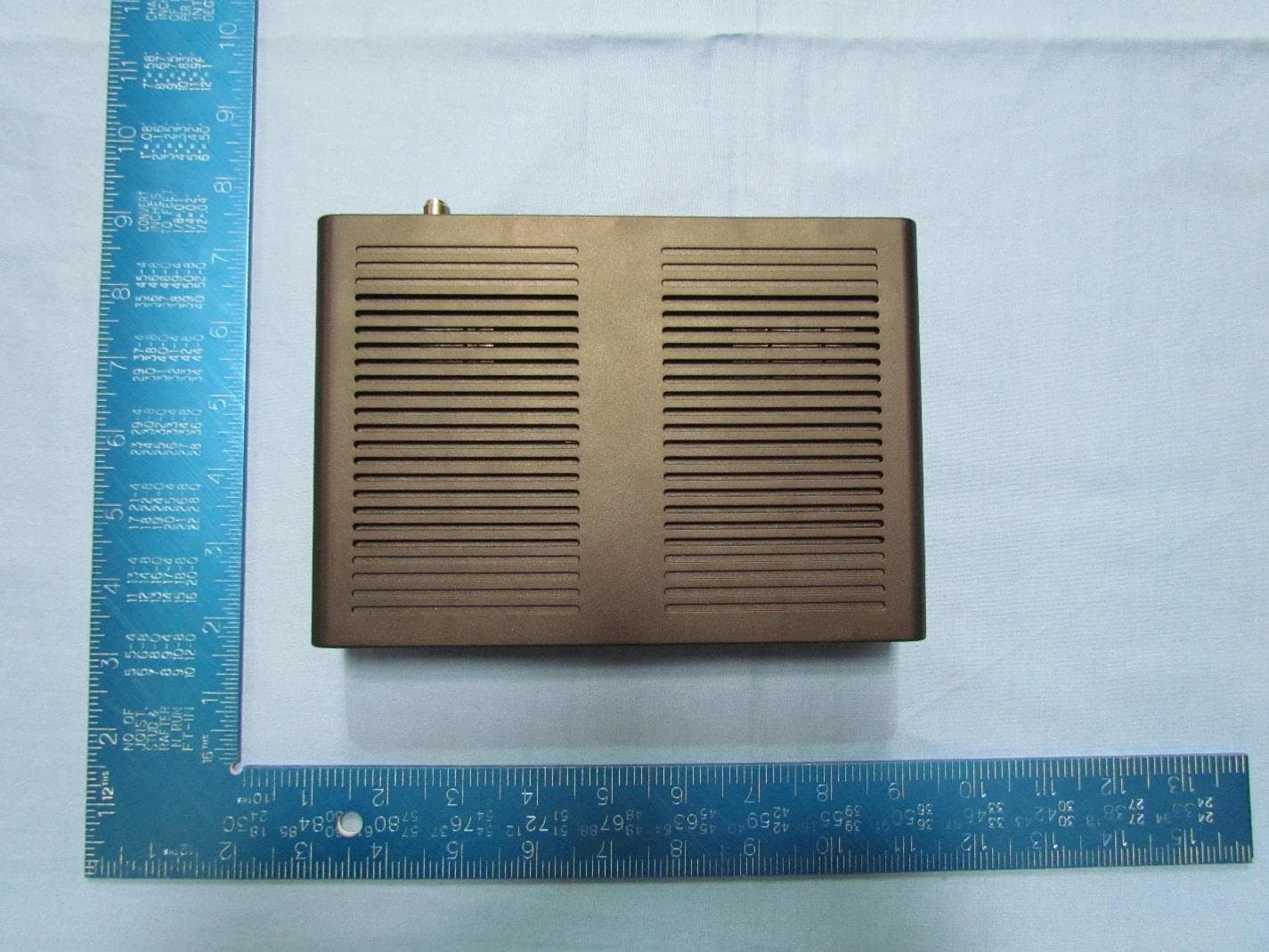
Click to zoom
Application Details
- Equipment Class
- NII - Unlicensed National Information Infrastructure TX
- Date of Grant
- Sep 22, 2015
- Application Purpose
- Original Equipment
- Date of Application
- Sep 21, 2015
- Equipment Note
- 11ac Wireless Ethernet Bridge
- Frequency Range
- 5745.00000000 - 5825.00000000
- Company
- Actiontec Electronics Inc
- Country
- United States
Documents & Files
Document Text
Text extracted from the exhibit documents filed with the FCC. Open a document above to read the original.
Users Manual
802.11ac MoCA 2.0 User Guide Wireless Ethernet Bridge Model # WCB5000 0535-00xx-000 rev. 1 Table of Contents Table of Contents 1 Introduction 3 Features 4 Getting to Know the Extender 5 Front Panel 5 Back Panel 6 Installing the Extender 7 Syncing Wi-Fi 7 Connecting the Extender 8 Accessing the Extender’s GUI 10 Status 13 Wireless Setup 14 Advanced Setup 20 1 WCB5000 Wireless Network Extender Specifications 23 Notices 25 Warranty 25 Important Safety Instructions 26 FCC Class B Equipment 27 Important Note on WiFi 28 2 Introduction The Actiontec WCB5000 is a wireless network extender with dual concurrent radios supporting both 2.4GHz and 5GHz operation in 802.11 a/b/g/n, and also 5GHz in 802.11ac. This allows the Extender to connect to everything from legacy wireless laptops, computers, and gaming platforms, up to the most current (and future) Apple and Android tablets, laptops, media platforms, and smartphones. The Extender works by being placed in a central location of the home, or in a location where the existing wireless signal is weak, and then being physically connected directly to your gateway/modem. This physical connection not only extends the signal, but allows the Extender to import and automatically configure itself with the same network ID/SSID and password currently in use and configured on the existing gateway/modem. This means that wherever you are in your house, your WiFi tablet, laptop, phone, or wireless device will automatically connect to Internet without anyone having to find a new network name or enter security keys. For users with newer mobile devices, tablets, and laptops, connections through the 5GHz radio can markedly increase the performance and speed of your WiFi connection, while freeing up the 2.4GHz band for legacy or older devices. ! ! 3 WCB5000 Wireless Network Extender Features •2.4GHz and 5GHz dual concurrent 802.11 a/b/g/n WiFi radios •5GHz 802.11ac WiFi radio •Four Gigabit Ethernet ports •One coaxial port (MoCA 2.0) •Integrated wireless networking with 2x2 802.11n and 2x2 802.11ac access point •Multiple security offerings, including, MAC address filtering, and WPA •Other options including WMM, IP address management, carrier remote support and management, and upgradable firmware. ! 4 Getting to Know the Extender This chapter describes the location and uses of the Extender’s LEDs, ports, and buttons. Front Panel The front panel features LEDs that illuminate green when power, available ports, and/or wireless bands are functioning and in use. ! 5 Power 2.4GHz radio LAN Coax 5GHz radio WCB5000 Wireless Network Extender Back Panel •Power port: used to connect the power adapter (external, 12V DC, 1.5A, made by Ktec, model #KSASB0241200150HU) to the Extender. •Reset button: restores the Extender back to the original factory default settings when held down for at least 10 seconds. •Coax port: used for connecting the Extender to a coaxial network. •Four-port Gigabit Ethernet switch: used for directly connecting the Extender to the gateway/modem or other Ethernet devices. •Labels: indicate the factory default GUI access username and password, network SSID names, and security keys. ! ! 6 Installing the Extender There are two parts to installing an Extender: syncing the Wi-Fi settings, and placing and connecting the Extender. Syncing Wi-Fi To sync the Extender with the gateway/modem’s Wi-Fi settings: 1.Place the Extender next to the gateway/modem. 2.Plug the Extender’s power adapter into the Power port of the Extender, and the other end into an electrical wall outlet. 3.Press the WPS button on both the Extender and the gateway/modem simultaneously for ten seconds. 4.Make sure the WPS button on the Extender is glowing green. If the WPS button glows red, try syncing the Wi-Fi settings again. The Extender can also be manually configured to connect with the gateway/modem’s wireless network (see “Wireless Setup” on page 14). The Extender is now synced with the gateway/modem’s Wi-Fi settings. Unplug the Extender and its power cable and continue on to the next section of this chapter, “Connecting the Extender.” 7 WCB5000 Wireless Network Extender Connecting the Extender Now that the Extender is synced with the gateway/modem’s wireless network, it can be connected to the gateway/modem’s MoCA network and placed in another area or room of the home/office. To do this: 1.Place the Extender in an area where the Wi-Fi signal is weak or spotty. A coaxial outlet must be available nearby. 2.Connect the included coaxial cable into the Coax port on the rear panel of the Extender. 3.Connect the other end of the coaxial cable into the nearby coaxial outlet. 4.Plug the Extender’s power adapter into the Power port of the Extender, and the other end into an electrical wall outlet. 5.If applicable, connect an Ethernet cable between one of the Extender’s LAN ports and the Ethernet port of a non-wireless device (wireless devices will connect via the wireless network). The configuration should look similar to the figure, below: ! 8 Installing the Extender 6.Wait until the Coax and Wireless LEDs on the front panel of the Extender glow green. This may take a few minutes. The Extender is now synced, installed, and extending the gateway/ modem’s wireless network in a previously weak area. Using a Coaxial Splitter If another device is using the coaxial outlet needed from step 3 in the previous procedure, perform the following steps: 1.Disconnect the coaxial cable from the coaxial outlet. 2.Connect a coaxial cable between the coaxial outlet and the single port on a two-way coaxial splitter. 3.Connect the coaxial cable disconnected in step 1of this procedure to one of the dual ports on the splitter. 4.Connect a coaxial cable between the Coax port of the Extender and the other dual port on the splitter. The final configuration should be similar to the inset in the figure on the previous page. ! 9 Accessing the Extender’s GUI The Extender features an onboard graphical user interface (GUI) that includes…
Text truncated - open the document above for the full version.
Cover Letter(s)
Actiontec Electronics, Inc. 760 North Mary Avenue • Sunnyvale • CA • 94085 • USA Phone (408) 752-7700 • Fax (408) 541-9003 • www.actiontec.com Letter of Authorization Date: August 13, 2015 Company: Actiontec Electronics, Inc. Address: 760 N. Mary Ave., Sunnyvale, CA 94085 Product Name: 11ac Wireless Ethernet Bridge with MoCA 2.0 Model Number: WCB5000 FCC Identifier: LNQWCB5000 We authorize MiCOM Labs Inc, 575 Boulder Court, Pleasanton, California 94566, USA, to act on our behalf on all matters concerning the above named equipment. Any individual within MiCOM Labs is authorized to act on our behalf and take action on the application. We declare that MiCOM Labs Inc, 575 Boulder Court, Pleasanton, California 94566, USA, is allowed to forward all information related to the approval project to the Federal Communication Commission and to discuss any issues concerning the approval application. Any and all acts carried out by MiCOM Labs on our behalf shall have the same effect as acts of our own. Angela Yao/Sr. Program Manager Phone: (408) 752-7700 Fax: (408) 541-9003 Email: [email protected] Solutions for the Digital Life™
Cover Letter(s)
Actiontec Electronics, Inc. 760 North Mary Avenue • Sunnyvale • CA • 94085 • USA Phone (408) 752-7700 • Fax (408) 541-9003 • www.actiontec.com September 22, 2015 Federal Communications Commission Office of Engineering and Technology Laboratory Division 7435 Oakland Mills Rd Columbia, MD 21046 Subject: FCC ID: LNQWCB5000 To Whom It May Concern: We hereby attest to the fact that we have applied the Declaration of Conformity procedure for a Class B Computer Peripheral to the digital portion of this composite filing. The procedures identified in 47CFR 2.948(d) and 2.948(e), along with the requirements listed in KDB 349827 have been followed. The report has been issued by MiCOM Labs Inc., in 575 Boulder Court, Pleasanton, California 94566, USA and can be identified by report number ATEC07-U2 Rev. A. Sincerely Yours, Angela Yao/Sr. Program Manager Phone: (408) 752-7700 Fax: (408) 541-9003 Email: [email protected] Solutions for the Digital Life™
Cover Letter(s)
Actiontec Electronics, Inc. 760 North Mary Avenue • Sunnyvale • CA • 94085 • USA Phone (408) 752-7700 • Fax (408) 541-9003 • www.actiontec.com Date: August 13, 2015 Office of Engineering Technology Federal Communications Commission 7435 Oakland Mills Road Columbia, MD 21046 Subject: Request for Confidentiality for FCC ID: LNQWCB5000 To Whom It May Concern, Pursuant to the provisions of Sections 0.457 and 0.459 of Commission's rules (47CFR0.457, 0.459), we are requesting the Commission to withhold the following attachment(s) as confidential document from public disclosure indefinitely. • Schematic Diagram • Block Diagram • Part List • Operational Description Above mentioned document contains detailed system and equipment description are considered as proprietary information in operation of the equipment. The public disclosure of above documents might be harmful to our company and would give competitor an unfair advantage in the market. In additional to above mentioned documents, pursuant to Public Notice DA 04-1705 of the Commission' s policy, in order to comply with the marketing regulations in 47 CFT §2.803 and the importation rules in 47 CFR §2.1204, while ensuring that business sensitive information remains confidential until the actual marketing of newly authorized devices. We are requesting the commission to grant shot-term confidentiality request on the following attachment(s) for 180 days after the grant as outlined in Public Notice DA 04-1705. • External Photos • Internal Photos • Test Setup Photos • User Manual It is our understanding that all measurement test reports, FCC ID label format and correspondent during certification review process cannot be granted as confidential documents and those information will be available for public review once the grant of equipment authorization is issued. Sincerely, Angela Yao/Sr. Program Manager Phone: (408) 752-7700 Fax: (408) 541-9003 Email: [email protected] Solutions for the Digital Life™
Cover Letter(s)
Actiontec Electronics, Inc. 760 North Mary Avenue • Sunnyvale • CA • 94085 • USA Phone (408) 752-7700 • Fax (408) 541-9003 • www.actiontec.com FCC KDB 848637 U-NII Client device without radar detection capability - Software Configuration Control Declaration Date: September 22, 2015 Federal Communications Commission Authorization and Evaluation Division 7435 Oakland Mills Road Columbia, MD 21046 Attn: OET Dept. Product: 11ac Wireless Ethernet Bridge with MoCA 2.0 Model Number: WCB5000 Regarding FCC KDB 848637 U-NII Client device without radar detection capability - Software Configuration Control “The applicant must provide in the equipment authorization application a software and operations description that discuss how the software and / or hardware is implemented to ensure that proper operations modes cannot be modified by an end user or an installer. Also, include an attestation that the device complies with the requirements for software configuration control as discussed in KDB Publication 594280 D01.” The software controlling the system and power levels are part of our software application binaries on the units and are not modifiable by end customers. Our software is controlled by our R&D and Manufacturing facilities. We declare that no third party will have software, or configuration control to program the device out of compliance of the technical rules under which it has been certified. Angela Yao/Sr. Program Manager Phone: (408) 752-7700 Fax: (408) 541-9003 Email: [email protected] Solutions for the Digital Life™
Cover Letter(s)
Actiontec Electronics, Inc. 760 North Mary Avenue • Sunnyvale • CA • 94085 • USA Phone (408) 752-7700 • Fax (408) 541-9003 • www.actiontec.com FCC Software Configuration Control Declaration Date: September 22, 2015 Federal Communications Commission Authorization and Evaluation Division 7435 Oakland Mills Road Columbia, MD 21046 Attn: OET Dept. Product: 11ac Wireless Ethernet Bridge with MoCA 2.0 Model Number: WCB5000 Regarding FCC Country Code Selection guidelines identified in KDB 594280. “All applications for equipment authorization for transmitters that can have radio parameters, or other technical parameters, reported to the Commission set by software must have an attestation indicating that no third party will have software, or configuration control, to program the device out of compliance of the technical rules under which it has been certified.” We declare that no third party will have software, or configuration control, to program the device out of compliance of the technical rules under which it has been certified. Angela Yao/Sr. Program Manager Phone: (408) 752-7700 Fax: (408) 541-9003 Email: [email protected] Solutions for the Digital Life™
Cover Letter(s)
Actiontec Electronics, Inc. 760 North Mary Avenue • Sunnyvale • CA • 94085 • USA Phone (408) 752-7700 • Fax (408) 541-9003 • www.actiontec.com Declaration of Similarity July 8, 2015 Re: FCC ID: LNQWCB5000 Actiontec Models: WCB5000, WEB5000 To whom it may concern: We, Actiontec Electronics, Inc., hereby declare the above mentioned 2 models have electrically identical Wireless circuitry with the same electromagnetic emissions and electromagnetic compatibility characteristics. The differences between these 2 models are as follows – WCB5000 – 11ac Wireless Ethernet Bridge with MoCA WEB5000 – 11ac Wireless Ethernet Bridge without MoCA Please contact me should there be need for any additional clarification or information. Sincerely, Angela Yao/Sr. Program Manager Phone: (408) 752-7700 Fax: (408) 541-9003 Email: [email protected] Solutions for the Digital Life™
External Photos
External Photos Extenral Side 1 View External Bottom View External Side 2 View External Side 3 View External Side 4 View External Top View
ID Label/Location Info
WCB5000 Label Artwork and Location (in red outlined area)
Internal Photos
ATEC07 Internal Photo Internal with Shield Internal Bottom Internal Top
RF Exposure Info
ATEC07 WCB5000 Maximum Permissible Exposure FCC, Part 15 §1.1310 Industry Canada RSS-Gen §5.6 Calculations for Maximum Permissible Exposure Levels Power Density = Pd (mW/cm 2 ) = EIRP/(4d 2 ) EIRP = P * G P = Peak output power (mW) G = Antenna numeric gain (numeric) d = Separation distance (cm) Numeric Gain = 10 ^ (G (dBi)/10) Because the EUT belongs to the General Population/Uncontrolled Exposure the limit of power density is 1.0 mW/cm 2 The calculations in the table below use highest gain antennas for the client EUT. Where the antenna gain exceeds 6dBi the transmitter power is reduced where necessary to meet the EIRP requirements. These calculations represent worst case in terms of the exposure levels. Freq. Band (MHz) Antenna Gain (dBi) Numeric Gain (numeric) Peak Output Power (dBm) Peak Output Power (mW) Calculated Safe Distance @ 1mW/cm 2 Limit(cm) Minimum Separation Distance (cm) 2400 – 2483.5 2.3 1.7 26.27 423.64 7.57 20.0 5725 - 5850 4.1 2.6 26.55 451.86 9.67 20.0 Assessment for simultaneous operation in 5.15-5.25 GHz and 5.8 GHz bands The Actiontec WCB5000 has two different radio modules. The device is DBDC “Dual Band Dual Concurrent” (autonomous transmission). The following assessment is based on simultaneous operation in the 5.15-5.25 GHz and 5.8 GHz (worst case) bands. Freq. Band (MHz) Antenna Gain (dBi) Numeric Gain (numeric) Peak Output Power (dBm) Peak Output Power (mW) Calculated Safe Distance @ 1mW/cm 2 Limit(cm) Minimum Separation Distance (cm) 5725 - 5850 4.1 2.6 26.55 451.86 9.67 20.0 2400 – 2483.5 2.3 1.7 26.27 423.64 7.57 20.0 EIRP Total 1895.03 mW 12.3 cm 20.0 cm Note: for mobile or fixed location transmitters the minimum separation distance is 20cm, even if calculations indicate the MPE distance to be less. Specification Maximum Permissible Exposure Limits FCC §1.1310 Limit = 1mW / cm 2 from 1.310 Table 1 Ref FCC KDB 447498 General RF Exposure Guidance RSS-Gen §5.6 Category I and Category II equipment shall comply with the applicable requirements of RSS-102. Laboratory Measurement Uncertainty for Power Measurements Measurement uncertainty 1.33 dB
Test Report
Company: Actiontec Electronics Inc. Test of: WCB5000, WEB5000 To: FCC CFR 47 Part 15 Subpart E 15.407 (non-DFS Bands) Report No.: ATEC07-U8 Rev A CONDUCTED TEST REPORT FROM Test of: Actiontec Electronics Inc. WCB5000, WEB5000 to To: FCC CFR 47 Part 15 Subpart E 15.407 (non-DFS Bands) Test Report Serial No.: ATEC07-U8 Rev A This report supersedes: NONE Applicant: Actiontec Electronics Inc. 760 N Mary Avenue Sunnyvale, California 94085 USA Product Function: 11ac Wireless Ethernet Bridge with MoCA 2.0 Issue Date: 18 th August 2015 This Test Report is Issued Under the Authority of: MiCOM Labs, Inc. 575 Boulder Court Pleasanton California 94566 USA Phone: +1 (925) 462-0304 Fax: +1 (925) 462-0306 www.micomlabs.com MiCOM Labs is an ISO 17025 Accredited Testing Laboratory Title: Actiontec Electronics Inc. WCB5000, WEB5000 To: FCC CFR 47 Part 15 Subpart E 15.407 (non-DFS Bands) Serial #: ATEC07-U8 Rev A Issue Date: 18 th August 2015 Page: 3 of 161 This test report may be reproduced in full only. The document may only be updated by MiCOM Labs personnel. All changes will be noted in the Document History section of the report. MiCOM Labs, 575 Boulder Court, Pleasanton, California 94566 USA, Phone: +1 (925) 462 0304, Fax: +1 (925) 462 0306, www.micomlabs.com Table of Contents 1. ACCREDITATION, LISTINGS & RECOGNITION................................................................................. 4 1.1. TESTING ACCREDITATION ......................................................................................................... 4 1.2. RECOGNITION ............................................................................................................................. 5 1.3. PRODUCT CERTIFICATION ........................................................................................................ 6 2. DOCUMENT HISTORY ......................................................................................................................... 7 3. TEST RESULT CERTIFICATE .............................................................................................................. 8 4. REFERENCES AND MEASUREMENT UNCERTAINTY ..................................................................... 9 4.1. Normative References ................................................................................................................... 9 4.2. Test and Uncertainty Procedure .................................................................................................. 10 5. PRODUCT DETAILS AND TEST CONFIGURATIONS ...................................................................... 11 5.1. Technical Details ......................................................................................................................... 11 5.2. Scope Of Test Program ............................................................................................................... 12 5.3. Equipment Model(s) and Serial Number(s) ................................................................................. 13 5.4. Antenna Details ........................................................................................................................... 13 5.5. Cabling and I/O Ports .................................................................................................................. 13 5.6. Test Configurations...................................................................................................................... 14 5.7. Equipment Modifications ............................................................................................................. 14 5.8. Deviations from the Test Standard .............................................................................................. 14 6. TEST SUMMARY ................................................................................................................................ 15 7. TEST EQUIPMENT CONFIGURATION(S) ......................................................................................... 16 7.1. Conducted ................................................................................................................................... 16 7.2. Radiated Emissions - 3m Chamber ......................................................................................... 18 7.3. ac Wireline Emission Test Set-up ............................................................................................ 20 8. MEASUREMENT AND PRESENTATION OF TEST DATA ............................................................... 21 9. TEST RESULTS .................................................................................................................................. 22 9.1. Peak Transmit Power .................................................................................................................. 22 9.2. 26 dB & 99% Bandwidth .............................................................................................................. 28 9.3. Power Spectral Density ............................................................................................................... 37 9.4. Radiated Spurious Emissions ...................................................................................................... 43 9.4.1. Radiated Spurious Emissions ............................................................................................ 43 9.4.2. Restricted Band-Edge Emissions ...................................................................................... 51 9.5. Radiated Digital Emissions .......................................................................................................... 64 9.6. ac Wireline Emissions.................................................................................................................. 67 A. APPENDIX - GRAPHICAL IMAGES .................................................................................................. 70 A.1. 26 dB & 99% Bandwidth ....................…
Text truncated - open the document above for the full version.
Test Setup Photos
Test Setup Photographs Test Setup - CE - Conducted Emissions ac Wireline Emissions Front View ac Wireline Emissions Rear View 1.1.1. Test Setup - RE#1 - Radiated Emissions - 3m Chamber Digital Emissions (0.03-1 GHz) Front View Digital Emissions (0.03-1 GHz) Rear View Radiated Emissions 1-6 GHz TX SE 1.1.2. Test Setup - RF#2 - Conducted RF conducted
Contact Information
Applicant
Brian Henrichs(President)
Technical Contact
Test Firm
Micom LabsGordon Hurst
Technical Specifications
| # | Rule Parts | Frequency Range | Power Output |
|---|---|---|---|
| 2 | 15E | 5.75 GHz - 5.83 GHz | 452.00 mW |
Other Applications from Actiontec Electronics Inc

LNQWF672
Dec 26, 2025Wi-Fi 7 Outdoor Mesh AP
Equipment Class
DTS - Digital Transmission System
LNQ-WF670G
Dec 09, 2025Wi-Fi 7 Outdoor Mesh AP
Equipment Class
DTS - Digital Transmission SystemLNQ-WF815-2
Apr 14, 2024Tri-band Wi-Fi 6E Wireless AP
Equipment Class
DTS - Digital Transmission System
LNQ-WF825
Mar 24, 2024Tri-band Wi-Fi 7 Wireless AP
Equipment Class
6ID - 15E 6 GHz Low Power Indoor Access Point
LNQ-WF810G-2
Mar 23, 2024Wi-Fi 6E Mesh Extender
Equipment Class
DTS - Digital Transmission System