LOBSRF304SRF304 Module
Cervis Inc.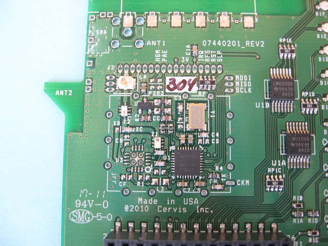
Click to zoom
Application Details
- Equipment Class
- DTS - Digital Transmission System
- Date of Grant
- Jun 23, 2011
- Application Purpose
- Original Equipment
- Date of Application
- Jun 23, 2011
- Equipment Note
- SRF304 Module
- Frequency Range
- 906.00000000 - 924.00000000
- Company
- Cervis Inc.
- Country
- United States
Documents & Files
Document Text
Text extracted from the exhibit documents filed with the FCC. Open a document above to read the original.
Users Manual
2011 Cervis, Inc. BU-9H16AF-8F-8V-RS Base Unit User Manual DN: U064.1-SmaRT_BU-9H16AF-8F-8V-RS ™ ™ SmaRT BU-9H16AF-8F-8V-RS This document is the property of Cervis, Inc. and cannot be copied, modified, e-mailed, or reproduced without the express prior written consent of Cervis, Inc. Cervis, Inc. reserves the right to change this manual or edit, delete, or modify any information without prior notification. FCC Statements 15.19 – Two Part Warning This device complies with Part 15 of the FCC rules. Operation is subject to the following two conditions: (1) This device may not cause harmful interference and (2) This device must accept any interference received, including interference that may cause undesired operation. 15.21 – Unauthorized Modification NOTICE: The manufacturer is not responsible for any unauthorized modifications to this equipment made by the user. Such modifications could void the user’s authority to operate the equipment. 15.105(b) – Note: This equipment has been tested and found to comply with the limits for a Class B digital device, pursuant to Part 15 of the FCC Rules. These limits are designed to provide reasonable protection against harmful interference in a residential installation. This equipment generates, uses and can radiate radio frequency energy and, if not installed and used in accordance with the instructions, may cause harmful interference to radio communications. However, there is no guarantee that interference will not occur in a particular installation. If this equipment does cause harmful interference to radio or television reception, which can be determined by turning the equipment off and on, the user is encouraged to try to correct the interference by one or more of the following measures: • Reorient or relocate the receiving antenna. • Increase the separation between the equipment and receiver. • Connect the equipment into an outlet on a circuit different from that to which the receiver is connected. Industry Canada Statement This device complies with Canadian RSS-210. The installer of this radio equipment must ensure that the antenna is located or pointed such that it does not emit RF field in excess of Health Canada limits for the general population; consult Safety Code 6, obtainable from Health Canada’s website www.hc-sc.gc-ca/rpb. Cervis, Inc. Visit our Web site at: www.cervisinc.com 2011 Cervis, Inc. All rights reserved. Content is subject to change without notice. 900MHz Base Unit Manual 2011 Cervis, Inc. i Table of Contents List of Figures ............................................................................................................................... i Related Documents ...................................................................................................................... ii Cervis Inc. Safety Precautions ................................................................................................... 1 1.0 BU-9H16AF-8F-8V-RS Base Unit ........................................................................................ 2 2.0 SmaRT BU-9H16AF-8F-8V-RS in SmaRT Remote Control Systems ............................... 3 2.1 BU-9H16AF-8F-8V-RS Base Unit Installation ................................................................. 4 2.1.1 SmaRT BU-9H16AF-8F-8V-RS-INT ............................................................................ 4 2.1.2 SmaRT BU-9H16AF-8F-8V-RS-EXT ........................................................................... 5 2.1.3 Optional Antenna Extension Kit Installation ................................................................. 6 2.1.4 SmaRT BU-9H16AF-8F-8V-RS Wiring ........................................................................ 7 3.0 Associate Mode .................................................................................................................... 9 4.0 Available Options ............................................................................................................... 10 5.0 Specifications ..................................................................................................................... 11 List of Figures Figure 1. SmaRT BU-9H16AF-8F-8V-RS-INT Base Unit .............................................................. 2 Figure 2. SmaRT BU-9H16AF-8F-8V-RS with SmaRT Remote Control Units ........................... 3 Figure 3. SmaRT BU-9H16AF-8F-8V-RS-INT Mounting Dimensions ......................................... 4 Figure 4. SmaRT BU-9H16AF-8F-8V-RS-EXT Mounting Dimensions ........................................ 5 Figure 5. Antenna Extension Kit Installation ............................................................................... 6 Figure 6. BU-9H16AF-8F-8V-RS P1 and P2 Field Wiring ............................................................ 8 List of Tables Table 1. BU-216F-INT P1 and P2 Cable Wiring ............................................................................ 7 Table 2. Available Options .......................................................................................................... 10 Table 3. SmaRT BU-9H16AF-8F-8V-RS Specifications ............................................................. 11 SmaRT BU-9H16AF-8F-8V-RS U064.1-SmaRT_BU-9H16AF-8F-8V-RS ii Definitions/Notes Associate/Association Mode where by SmaRT handhelds and base units are paired for operation (ID’s exchanged). This mode is used to commission spare handhelds or base units. DSSS Direct Sequence Spread Spectrum; an advance wireless communication technology. Disassociation The process of up-pairing a handheld from a base units ID memory. PTO Push-to-Operate: Command broadcast only while a button is depressed. The command ends when the button is released. Latch Command broadcast while a switch is placed in position or when a button is pressed. The command ends when switch is repositioned or when the button is released, or in some cases when the button is pressed again. SmaRT Base Unit I/O unit to which the contr…
Text truncated - open the document above for the full version.
Cover Letter(s)
101210-19 Confidential 170 Thorn Hill Road • Warrendale, PA 15086 • 724-741-9000 Authority to Act as Agent Date: 26 May 2011 American Certification Body, Inc. 6731 Whittier Avenue Suite C110 McLean, VA 22101 To Whom It May Concern: Steve Koster/Washington Laboratories is authorized to act on our behalf, until otherwise notified, for applications to American Certification Body, Inc. (ACB). We certify that we are not subject to denial of federal benefits, that includes FCC benefits, pursuant to Section 5301 of the Anti-Drug Abuse Act of 1988, 21 U.S.C. 862. Further, no party, as defined in 47 CFR 1.2002 (b), to the application is subject to denial of federal benefits, that includes FCC benefits. Thank you, Agency Agreement Expiration Date: 12 Months By: Anthony DiTomasso Title: Manager, Engineering email: [email protected] On behalf of: Cervis Inc. Telephone: 724-741-9000
Cover Letter(s)
170 Thorn Hill Road • Warrendale, PA 15086 Phone 724.741.9000 • Fax 724.741.9001 www.cervisinc.com Request for Confidentiality Date: 24 May 2011 Subject: Confidentiality Request for: FCC ID: LOBSRF304 and IC ID: 7955A-SRF304 Pursuant to FCC 47 CRF 0.457(d) and 0.459 and IC RSP-100, Section 10, the applicant requests that a part of the subject FCC application be held confidential. Type of Confidentiality Requested Exhibit Short Term Permanent Block Diagrams Short Term External Photos Short Term Permanent Internal Photos Short Term Permanent Operation Description/Theory of Operation Short Term Permanent Parts List & Placement/BOM Short Term Permanent Tune-Up Procedure Short Term Permanent Schematics Short Term Test Setup Photos Short Term Permanent User’s Manual Cervis Inc. has spent substantial effort in developing this product and it is one of the first of its kind in industry. Having the subject information easily available to "competition" would negate the advantage they have achieved by developing this product. Not protecting the details of the design will result in financial hardship. Sincerely, By: Anthony DiTomasso Title: Manager, Engineering On behalf of: Cervis Inc. Telephone: 724-741-9000
External Photos
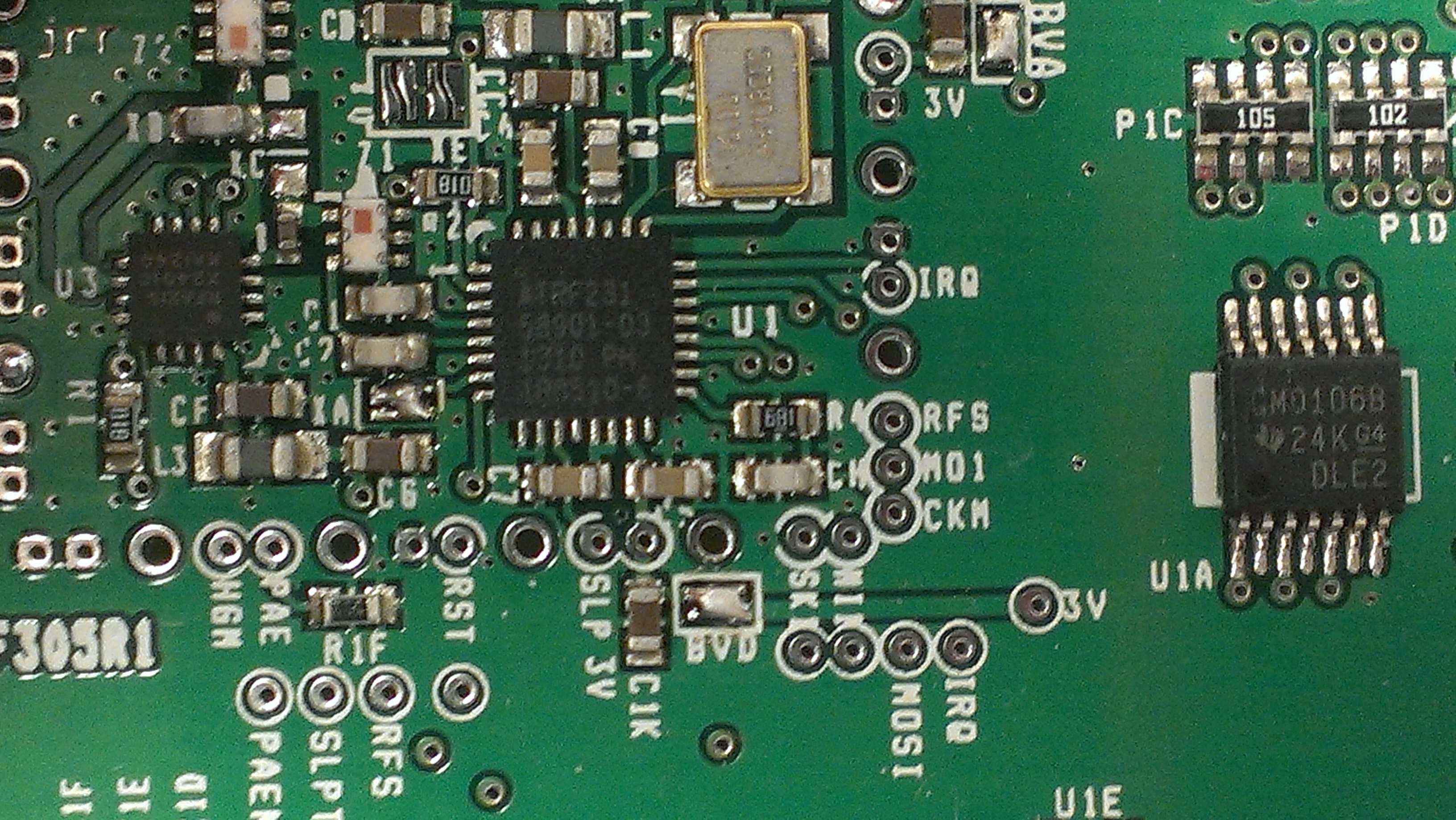
Internal/External Photos ©2008 Washington Laboratories, Ltd FCC ID: LOBSRF304/IC: 7955A-SRF304 2dBi Whip Antenna Internal/External Photos ©2008 Washington Laboratories, Ltd FCC ID: LOBSRF304/IC: 7955A-SRF304 Bottom Internal/External Photos ©2008 Washington Laboratories, Ltd FCC ID: LOBSRF304/IC: 7955A-SRF304 Closeup of RF Section Internal/External Photos ©2008 Washington Laboratories, Ltd FCC ID: LOBSRF304/IC: 7955A-SRF304 Top w splatch antenna Internal/External Photos ©2008 Washington Laboratories, Ltd FCC ID: LOBSRF304/IC: 7955A-SRF304 Top w UFL connector for external whip Internal/External Photos ©2008 Washington Laboratories, Ltd FCC ID: LOBSRF304/IC: 7955A-SRF304 Top without shield Internal/External Photos ©2008 Washington Laboratories, Ltd FCC ID: LOBSRF304/IC: 7955A-SRF304 Whip antenna attached to module
ID Label/Location Info
Cervis SmaRT 915MHz Module FCC ID: LOBSRF304 IC: 7955A-SRF304 Cervis SmaRT 915MHz Module FCC ID: LOBSRF304 IC: 7955A-SRF304 Cervis SmaRT 915MHz Module FCC ID: LOBSRF304 IC: 7955A-SRF304 Rev 0 15.19 – Two Part Warning This device complies with Pa rt 15 of the FCC rules. Operation is subject to the following two conditions: (1) This device may not cause harmful interference and (2) This device must accept any interference received, including interference that may cause undesired operation. 15.21 – Unauthorized Modification NOTICE: The manufacturer is not responsible for any unauthorized modifications to this equipment made by the user. Such modifications could void the user’s authority to operate the equipment. FCC Statements: CONTAINS: FCC ID: LOBSRF304 IC: 7955A-SRF304 Cervis SmaRT™ Base Unit Label Location
Internal Photos
Internal/External Photos ©2008 Washington Laboratories, Ltd FCC ID: LOBSRF304/IC: 7955A-SRF304 2dBi Whip Antenna Internal/External Photos ©2008 Washington Laboratories, Ltd FCC ID: LOBSRF304/IC: 7955A-SRF304 Bottom Internal/External Photos ©2008 Washington Laboratories, Ltd FCC ID: LOBSRF304/IC: 7955A-SRF304 Closeup of RF Section Internal/External Photos ©2008 Washington Laboratories, Ltd FCC ID: LOBSRF304/IC: 7955A-SRF304 Top w splatch antenna Internal/External Photos ©2008 Washington Laboratories, Ltd FCC ID: LOBSRF304/IC: 7955A-SRF304 Top w UFL connector for external whip Internal/External Photos ©2008 Washington Laboratories, Ltd FCC ID: LOBSRF304/IC: 7955A-SRF304 Top without shield Internal/External Photos ©2008 Washington Laboratories, Ltd FCC ID: LOBSRF304/IC: 7955A-SRF304 Whip antenna attached to module
RF Exposure Info
Certificates and reports shall not be reproduced except in full, without the written permission of Washington Labs, Limited. Maximum Permissible Exposure Evaluation For the Cervis Inc. LOBSRF304 FCC ID: LOBSRF304 IC: 7955A-SRF304 June 17, 2011 WLL Report: 11992-MPE Prepared for: CERVIS INC. 170 THORN HILL ROAD WARRENDALE, PA 15086 Prepared by: WASHINGTON LABORATORIES, LTD. 7560 LINDBERGH DRIVE G AITHERSBURG, MARYLAND 20879 Testing Certificate AT-1448 Cervis Inc. LOBSRF304 RF Exposure Test Report June, 2011 WLL Report #11992-MPE - ii - © 2011 Washington Laboratories, Ltd. Maximum Permissible Exposure Evaluation For the Cervis Inc. LOBSRF304 June 17, 2011 WLL Report # 11992-MPE Prepared by: James Ritter EMC Compliance Engineer Reviewed by: Steven D. Koster EMC Operations Manager Cervis Inc. LOBSRF304 RF Exposure Test Report June, 2011 WLL Report #11992-MPE - iii - © 2011 Washington Laboratories, Ltd. Abstract This report has been prepared on behalf of Cervis Inc. LOBSRF304 to document the findings of the maximum permissible exposure evaluation on the Cervis Inc. LOBSRF304. The purpose of this evaluation is to establish a minimum safe distance as per the RF exposure requirements as defined in FCC §1.1307, §1.1310 & Industry Canada RSS-102 issue 4. This report documents the results of testing to the requirements of: CFR Title 47 Volume 1 Practice and Procedure; (1.1307) Environmental Assessments The Evaluation was performed by Washington Laboratories, Ltd, 7560 Lindbergh Drive, Gaithersburg, MD 20879. Washington Laboratories, Ltd. has been accepted as an EMC Conformity Assessment Body (CAB) under the United States/European Union Memorandum of Agreement. Washington Laboratories, Ltd. is accredited by ACLASS under Testing Certificate AT-1448. Revision History Reason Date Rev 0 Initial Release June 17, 2011 Cervis Inc. LOBSRF304 RF Exposure Test Report June, 2011 WLL Report #11992-MPE - iv - © 2011 Washington Laboratories, Ltd. Table of Contents Abstract .................................................................................................................................................................... ii 1 Introduction ................................................................................................................................................ 1 2 Requirements .............................................................................................................................................. 1 2.1 Transmitter Categories ............................................................................................................................. 1 2.2 Exposure Categories ................................................................................................................................ 1 3 Device Summary ......................................................................................................................................... 3 4 Radio Frequency Radiation Exposure Evaluation .................................................................................. 3 List of Tables Table 1: MPE Limits ..................................................................................................................................................2 Table 2: Device Summary of the LOBSRF304 ..........................................................................................................3 Table 3: Transmitter MPE Calculation Summary ......................................................................................................4 Cervis Inc. LOBSRF304 RF Exposure Test Report June, 2011 WLL Report #11992-MPE - Page 1 of 4 - © 2011 Washington Laboratories, Ltd. 1 Introduction This report has been prepared on behalf of Cervis Inc. LOBSRF304 module to show compliance with the RF exposure requirements as defined in FCC §1.1307 & Industry Canada RSS-102 issue 4. Testing supporting this evaluation was performed at Washington Laboratories, Ltd, 7560 Lindbergh Drive, Gaithersburg, MD 20879. Washington Laboratories, Ltd. has been accepted as an EMC Conformity Assessment Body (CAB) under the United States/European Union Memorandum of Agreement. Washington Laboratories, Ltd. is accredited with ACLASS under Testing Certificate AT-1448. 2 Requirements Three different categories of transmitters are defined by the FCC in OET Bulletin 65. These categories are fixed installation, mobile, and portable. Additionally, the FCC categorizes the use of the devices based on the user’s awareness and the ability to exercise control over his or her exposure. The two categories are defined as Occupational/Controlled Exposure and General Population/Uncontrolled Exposure. 2.1 Transmitter Categories 2.1.1 Fixed Installations A fixed location means that the device, including its antenna, is physically secured at a permanent location and is not able to be easily moved to another location. Additionally, distance to humans from the antenna is maintained to at least 2 meters. 2.1.2 Mobile Devices A mobile device is defined as a transmitting device designed to be used in other than fixed locations and to be generally used in such a way that a separation distance of at least 20 centimeters is normally maintained between the transmitter's radiating structures and the body of the user or nearby persons. Transmitters designed to be used by consumers or workers that can be easily re-located, such as a wireless modem operating in a laptop computer, are considered mobile devices if they meet the 20 centimeter separation requirement. The FCC rules for evaluating mobile devices for RF compliance are found in 47 CFR §2.1091. 2.1.3 Portable Devices A portable device is defined as a transmitting device designed to be used so that the radiating structure(s) of the device is/are within 20 centimeters of the body of the user. Portable device requirements are found in Section 2.1093 of the FCC's Rules (47 CFR§2.1093). 2.2 Exposure Categories The limits for exposure are determined b…
Text truncated - open the document above for the full version.
Test Report
Certificates and reports shall not be reproduced except in full, without the written permission of Washington Laboratories, Limited. FCC & Industry Canada Certification Test Report For the Cervis, Inc. LOBSRF304 Module FCC ID: LOBSRF304 IC: 7955A-SRF304 WLL JOB# 11992-01 Rev 1 June 17, 2011 Re-issued June 22, 2011 Prepared for: Cervis, Inc. 170 Thorn Hill Road, Warrendale, PA, 15086 USA Prepared By: Washington Laboratories, Ltd. 7560 Lindbergh Drive Gaithersburg, Maryland 20879 Testing Certificate AT-1448 Cervis, Inc. LOBSRF304 Module FCC Certification Test Report June, 2011 WLL Report #11992-01 Rev 1 - ii - © 2011 Washington Laboratories, Ltd. FCC & Industry Canada Certification Test Report for the Cervis, Inc. LOBSRF304 Module FCC ID: LOBSRF304 IC: 7955A-SRF304 June 17, 2011 Re-issued June 22, 2011 WLL JOB# 11992-01 Rev 1 Prepared by: James Ritter EMC Compliance Engineer Reviewed by: Steven D. Koster EMC Operations Manager Cervis, Inc. LOBSRF304 Module FCC Certification Test Report June, 2011 WLL Report #11992-01 Rev 1 - iii - © 2011 Washington Laboratories, Ltd. Abstract This report has been prepared on behalf of Cervis, Inc. to support the attached Application for Equipment Authorization. The test report and application are submitted for a Direct Sequence Spread Spectrum Transmitter under Part 15.247 (10/2009) of the FCC Rules and Regulations and Spectrum Management and Telecommunications Policy RSS-210 issue 8 of Industry Canada. This Certification Test Report documents the test configuration and test results for the Cervis, Inc. LOBSRF304 Module. Testing was performed on an Open Area Test Site (OATS) of Washington Laboratories, Ltd, 7560 Lindbergh Drive, Gaithersburg, MD 20879. Site description and site attenuation data have been placed on file with the FCC's Sampling and Measurements Branch at the FCC laboratory in Columbia, MD. The Industry Canada OATS numbers are 3035A-1 and 3035A-2 for Washington Laboratories, Ltd. Site 1 and Site 2, respectively. Washington Laboratories, Ltd. has been accepted by the FCC and approved by ACLASS under Certificate AT-1448 as an independent FCC test laboratory. The Cervis, Inc. LOBSRF304 Module complies with the limits for a Direct Sequence Spread Spectrum Transmitter under FCC Part 15.247 and Industry Canada RSS-210. Revision History Description of Change Date Rev 0 Initial Release June 17, 2011 Rev 1 Correct Table 1 and Figure 19 June 22, 2011 Cervis, Inc. LOBSRF304 Module FCC Certification Test Report June, 2011 WLL Report #11992-01 Rev 1 - iv - © 2011 Washington Laboratories, Ltd. Table of Contents Abstract ........................................................................................................................................... ii 1 Introduction ..............................................................................................................1 1.1 Compliance Statement .................................................................................................... 1 1.2 Test Scope ....................................................................................................................... 1 1.3 Contract Information ....................................................................................................... 1 1.4 Test Dates ....................................................................................................................... 1 1.5 Test and Support Personnel ............................................................................................ 1 1.6 Abbreviations .................................................................................................................. 2 2 Equipment Under Test .............................................................................................3 2.1 EUT Identification & Description .................................................................................. 3 2.2 Test Configuration .......................................................................................................... 3 2.3 Testing Algorithm ........................................................................................................... 3 2.4 Test Location .................................................................................................................. 4 2.5 Measurements ................................................................................................................. 4 2.5.1 References ................................................................................................................... 4 2.6 Measurement Uncertainty ............................................................................................... 4 3 Test Equipment ........................................................................................................6 4 Test Results ..............................................................................................................7 4.1 Test Summary ................................................................................................................. 7 4.2 Occupied Bandwidth: (FCC Part §15.247 (2)) ............................................................... 8 4.3 RF Power Output: (FCC Part §15.247(b)) .................................................................... 12 4.4 Power Spectral Density (Section §15.247(e)) ............................................................... 16 4.5 Conducted Spurious Emissions at Antenna Terminals (FCC Part §15.247(c)) ............ 20 4.5.1 Band Edge Compliance ............................................................................................. 33 4.6 AC Conducted Emissions (FCC Part §15.207)............................................................. 35 4.6.1 Requirements ............................................................................................................ 35 4.6.2 Test Data ..........................................................................................................…
Text truncated - open the document above for the full version.
Test Setup Photos
Test Setup Photos ©2008 Washington Laboratories, Ltd Bench Test Setup Photos ©2008 Washington Laboratories, Ltd Module Extended From Support BU916 Hose Test Setup Photos ©2008 Washington Laboratories, Ltd RE Front Splatch Antenna Test Setup Photos ©2008 Washington Laboratories, Ltd RE Rear Platch upright Test Setup Photos ©2008 Washington Laboratories, Ltd RE rear spatch antenna Test Setup Photos ©2008 Washington Laboratories, Ltd RE Whip Back Test Setup Photos ©2008 Washington Laboratories, Ltd RE Whip Front
Contact Information
Applicant
Anthony Michael Di Tommaso(Manager, Engineering)
Technical Contact
Washington LabsSteve Koster
[email protected]301-216-1500
7560 Lindbergh Drive · Gaithersburg · United States
Test Firm
Washington Laboratories, Ltd.Steve Koster
Technical Specifications
| # | Rule Parts | Frequency Range | Power Output |
|---|---|---|---|
| 1 | 15C | 906 MHz - 924 MHz | 9.25 mW |
Other Applications from Cervis Inc.
LOBSRF305
Jul 10, 2014SRF305 Receive/Transmit Module
Equipment Class
DTS - Digital Transmission System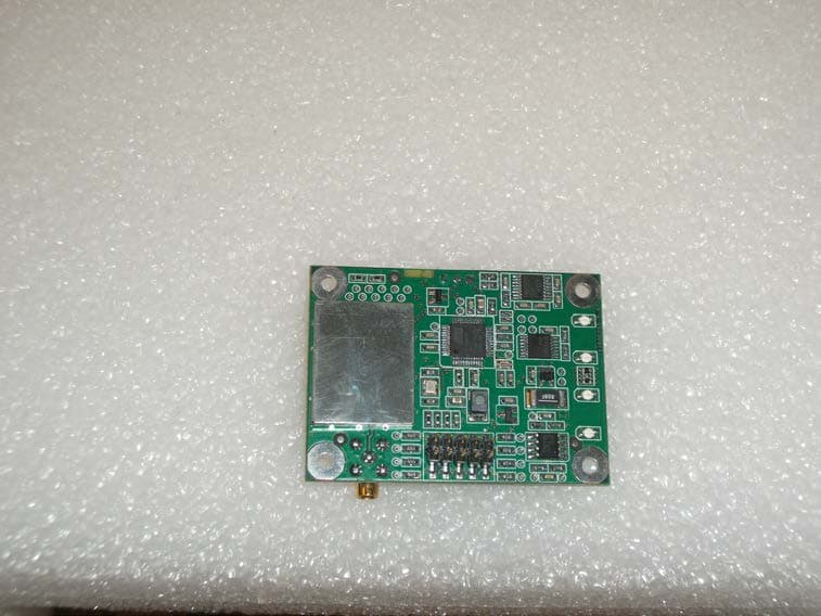
LOBMRF450
Mar 26, 2014LongRT Radio
Equipment Class
DSC - Part 15 Security/Remote Control Transmitter
LOB9H06
Mar 19, 2014SmaRT Portable Radio HH-9H06
Equipment Class
DTS - Digital Transmission System
LOB2H06
Jan 12, 2014SmaRT Portable Radio
Equipment Class
DTS - Digital Transmission System
LOBSHH900
Feb 05, 2008Direct Sequence TX
Equipment Class
DTS - Digital Transmission System