LX8765SLow Power Automitive Security Transmitter
Bayerische Motoren Werke AG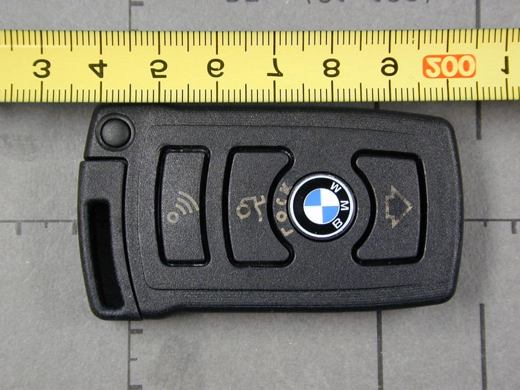
Click to zoom
Application Details
- Equipment Class
- DSC - Part 15 Security/Remote Control Transmitter
- Date of Grant
- Jun 27, 2001
- Application Purpose
- Original Equipment
- Date of Application
- Jun 27, 2001
- Equipment Note
- Low Power Automitive Security Transmitter
- Frequency Range
- 868.40000000 - 868.40000000
- Company
- Bayerische Motoren Werke AG
- Country
- Germany
Documents & Files
Document Text
Text extracted from the exhibit documents filed with the FCC. Open a document above to read the original.
External Photos
FCC ID LX8765S FCC ID: LX8765S External Photographs FCC ID LX8765S
ID Label/Location Info
FCC ID LX8765S FCC ID: LX8765S Label Information
Internal Photos
FCC ID LX8765S FCC ID: LX8765S Internal Photographs FCC ID LX8765S
Test Report
Page 1 of 46 Pages EMI/EMC-TestcenterEMV-Pr ̧fzentrum Straubing, January 22, 2001 T E S T - R E P O R T No. 50217-00696-1 for Funkfernbedienung 868 MHz, Typ 765 Remote control transmitter Applicant:Bayerische Motorenwerke AG Purpose of testing:To show compliance with FCC Code of Federal Regulations, Part 15 Subpart C, Section ß15.231 Industry Canada Radio Standards Specification RSS-210 Issue 2, Section 6.1 (Category I Equipment) Note: The test data of this report relate only to the individual item which has been tested. This report shall not be reproduced except in full extent without the written approval of the testing laboratory. Test report for FCC Part 15 Subpart CTest Report No. 50217-00696-1 Page 2 of 46 Pages EMI/EMC-TestcenterEMV-Pr ̧fzentrum Table of Contents 1. Administrative Data ..............................................................................................3 2. Identification of Test Laboratory ...........................................................................4 3. Summary of Test Results.....................................................................................5 4. Operation Mode of EUT .......................................................................................6 5. Configuration of EUT and Peripheral Devices ......................................................7 6. Measuring Methods..............................................................................................8 6.1. Bandwidth of Emission(FCC ß15.231.c / RSS-210 Section 6.1.1.c) ..........................................................................................................8 6.2. Radiated Emission 30 MHz - 1 GHz (FCC ß15.205.a,b, ß15.209, ß15.231.b / RSS-210 Sections 6.1.1.b, 6.3) ...................................9 6.3. Radiated Emission 1 GHz - 8.7 GHz (FCC ß15.205.a,b, ß15.209, ß15.231.b / RSS-210 Sections 6.1.1.b, 6.3) .................................11 7. Equipment List ...................................................................................................13 8. Photographs Taken During Testing....................................................................15 9. List of Measurements.........................................................................................20 9.1. List of Measurements According To FCC Part 15 Subpart C ......................21 9.2. List of Measurements According To Industry Canada RSS- 210 22 10. Referenced Regulations.....................................................................................23 11. Test Results .......................................................................................................24 Test report for FCC Part 15 Subpart CTest Report No. 50217-00696-1 Page 3 of 46 Pages EMI/EMC-TestcenterEMV-Pr ̧fzentrum 1.Administrative Data Equipment Under Test (EUT):Funkfernbedienung 868 MHz, Typ 765 Serial number(s):01 Type of equipment:Remote control transmitter Parts/accessories:--- FCC-ID:--- Applicant:Bayerische Motorenwerke AG (full address)Petuelring 130 D-80788 M ̧nchen Contract identification:--- Contact person:Mr. Hochleitner Manufacturer:Bayerische Motorenwerke AG Receipt of EUT:December 6, 2000 Date of test:December 2000 to January 2001 Note:--- Responsible for testing:Rupert Kohlh‰ufl Responsible for test report:Rupert Kohlh‰ufl (cj) Test report for FCC Part 15 Subpart CTest Report No. 50217-00696-1 Page 4 of 46 Pages EMI/EMC-TestcenterEMV-Pr ̧fzentrum 2.Identification of Test Laboratory Test Laboratory:Senton GmbH EMI/EMC Test Center (full address):Aeussere Fruehlingstrasse 45 D-94315 Straubing Germany Contact person:Mr. Johann Roidt Communication:Telephone(+49) 0 94 21 / 55 22-0 Fax (+49) 0 94 21 / 55 22-99 eMail:[email protected] FCC registration number:90926 Industry Canada file number:IC 3050 Test report for FCC Part 15 Subpart CTest Report No. 50217-00696-1 Page 5 of 46 Pages EMI/EMC-TestcenterEMV-Pr ̧fzentrum 3.Summary of Test Results The tested sample complies with the requirements set forth in the Code of Regulations Part 15 Subpart C, Section ß15.231 (intentional radiators) of the Federal Communication Commission (FCC) and the Radio Standards Specification RSS-210 Issue 2, Section 6.1 for Low Power Licence-Exempt Radiocommuniction Devices of Industry Canada. Johann RoidtRupert Kohlh‰ufl Technical ManagerTest Engineer Test report for FCC Part 15 Subpart CTest Report No. 50217-00696-1 Page 6 of 46 Pages EMI/EMC-TestcenterEMV-Pr ̧fzentrum 4.Operation Mode of EUT Transmitter in TX mode Test report for FCC Part 15 Subpart CTest Report No. 50217-00696-1 Page 7 of 46 Pages EMI/EMC-TestcenterEMV-Pr ̧fzentrum 5.Configuration of EUT and Peripheral Devices Configuration of cables of EUT --- Configuration of peripheral devices connected to EUT --- Test report for FCC Part 15 Subpart CTest Report No. 50217-00696-1 Page 8 of 46 Pages EMI/EMC-TestcenterEMV-Pr ̧fzentrum 6.Measuring Methods 6.1.Bandwidth of Emission(FCC ß15.231.c / RSS-210 Section 6.1.1.c) The Bandwidth of Emission is measured with a spectrum analyzer connected to measuring antenna (radiated measurement) or test fixture while EUT is operating in transmit mode with modulation at the appropriate center frequency. To increase received signal level distance to EUT is reduced (appropriate level offset is included). The spectrum analyzer was set to: RBW = 10 kHz, VBW = 10 kHz, span = 1 MHz, sweep = 40 ms See figure 1 for the measurement setup. Test equipment used (see equipment list for details): 02, 55, 67 5 2 1 4 3 Figure 1: Measurement setup for bandwidth of emission test 1Transmitter (EUT)3Test fixture 2Wooden table4Test cable 5Spectrum analyzer Test report for FCC Part 15 Subpart CTest Report No. 50217-00696-1 Page 9 of 46 Pages EMI/EMC-TestcenterEMV-Pr ̧fzentrum 6.2.Radiated Emission 30 MHz - 1 GHz (FCC ß15.205.a,b, ß15.209, ß15.231.b / RSS-210 Sections 6.1.1.b, 6.3) Radiated emissions are measured over the frequency range from 30 MHz to 1 GHz. The bandwidth of the EMI-receiver is set to 120 kHz and the det…
Text truncated - open the document above for the full version.
Test Setup Photos
Test report for FCC Part 15 Subpart CTest Report No. 50217-00696-1 Page 16 of 46 Pages EMI/EMC-TestcenterEMV-Pr ̧fzentrum Photos No. 8.1 - 8.2 Test setup for radiated emission pre-test 30 MHz - 1 GHz and final test 1 GHz - 8.7 GHz (semi anechoic room) Test report for FCC Part 15 Subpart CTest Report No. 50217-00696-1 Page 17 of 46 Pages EMI/EMC-TestcenterEMV-Pr ̧fzentrum Photos No. 8.3 - 8.4 Test setup for radiated emission pre-test 30 MHz - 1 GHz and final test 1 GHz - 8.7 GHz (semi anechoic room) - continued Test report for FCC Part 15 Subpart CTest Report No. 50217-00696-1 Page 18 of 46 Pages EMI/EMC-TestcenterEMV-Pr ̧fzentrum Photos No. 8.5 - 8.6 Test setup for radiated emission pre-test 30 MHz - 1 GHz and final test 1 GHz - 8.7 GHz (semi anechoic room) continued Test report for FCC Part 15 Subpart CTest Report No. 50217-00696-1 Page 19 of 46 Pages EMI/EMC-TestcenterEMV-Pr ̧fzentrum Photos No. 8.7 - 8.8 Test setup for radiated emission final test 30 MHz - 1 GHz (open area test site)
Contact Information
Applicant
Richard Hochleitner
Technical Contact
Senton GmbHJohann Roidt
[email protected]+49 9421 55 22 13
Aeussere Fruehlingstrasse 45 · Straubing · Germany
Test Firm
TUV SUD Product Service GmbH PS-EMC-STRRainer Heller
Technical Specifications
| # | Rule Parts | Frequency Range | Power Output |
|---|---|---|---|
| 1 | 15.231 | 868.4 MHz - 868.4 MHz | - |
Other Applications from Bayerische Motoren Werke AG
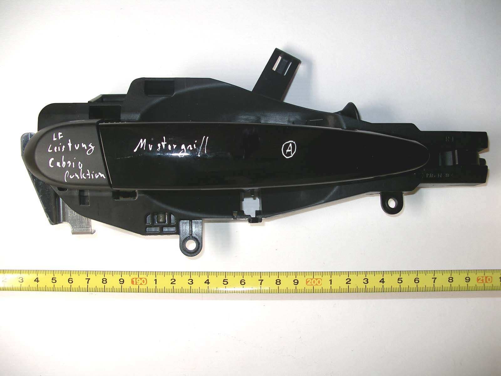
LX8CAS93
Nov 19, 2006Comfort Access System
Equipment Class
DCD - Part 15 Low Power Transmitter Below 1705 kHz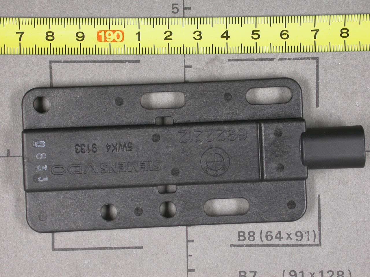
LX8PGS
May 23, 2004Automotive Inductive Comfort Access System
Equipment Class
DCD - Part 15 Low Power Transmitter Below 1705 kHz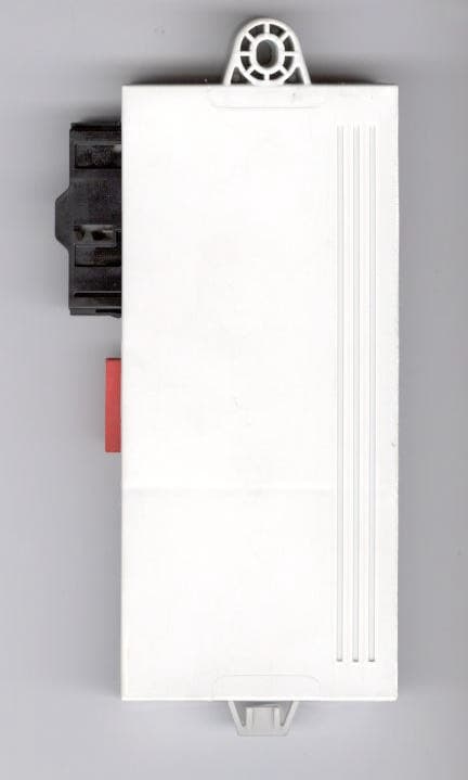
LX8CAS89X
May 16, 2004Transceiver for Car Immobilizer
Equipment Class
DCD - Part 15 Low Power Transmitter Below 1705 kHz
LX8CAS2
Dec 17, 2002Inductive Reader
Equipment Class
DCD - Part 15 Low Power Transmitter Below 1705 kHz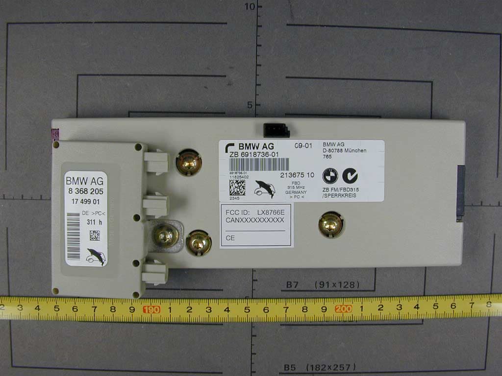
LX8766E
Feb 15, 2002Security Receiver
Equipment Class
CYY - Communications Receiver used w/Pt 15 Transmitter