LX8CAS93Comfort Access System
Bayerische Motoren Werke AG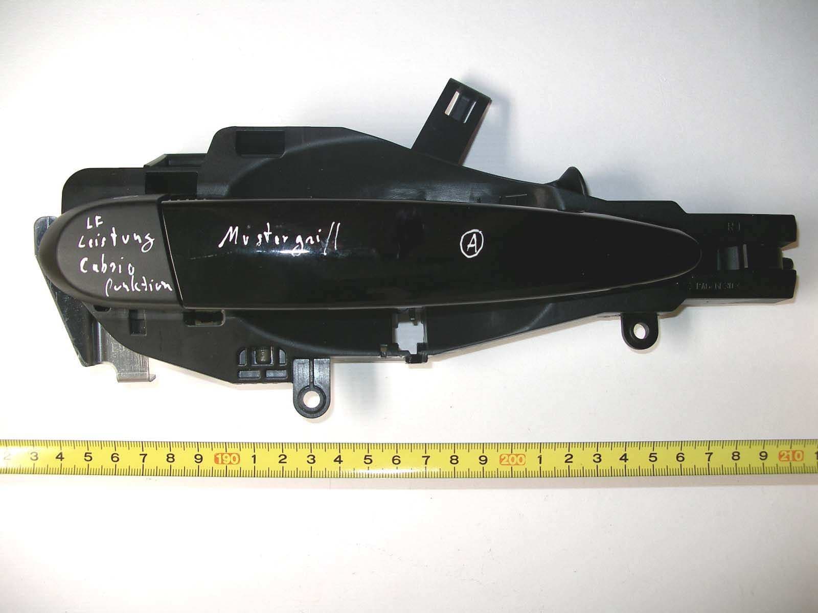
Click to zoom
Application Details
- Equipment Class
- DCD - Part 15 Low Power Transmitter Below 1705 kHz
- Date of Grant
- Nov 19, 2006
- Application Purpose
- Original Equipment
- Date of Application
- Nov 19, 2006
- Equipment Note
- Comfort Access System
- Frequency Range
- 0.12528000 - 0.12528000
- Company
- Bayerische Motoren Werke AG
- Country
- Germany
Documents & Files
Document Text
Text extracted from the exhibit documents filed with the FCC. Open a document above to read the original.
Users Manual
Huf Hülsbeck & Fürst 04.09.06 PDET/Witte Functional Description / User Manual for Comfort Access System Huf Hülsbeck & Fürst 04.09.06 PDET/Witte 1. Functional Description - Comfort Access System (CA) 2. General system description The CA-system enables convenient utilization of the vehicle. To use the vehicle, the driver only needs to take the key along with him/her. The vehicle communicates with the system inductively via antennas. These antennas are driven inductively with a frequency of 125 kHz. The system's range is limited in a defined fashion by damping the body sheet metal. In the vehicle interior, the ranges of the various antennas overlap, which enables location of the key. 3. Passive access control An approximating of the hand to the door handle, as well as by pulling the door handle is recognized over sensors. The door handle give this information over a CAS-Bus telegram to the CAS and at the same time the handle sends over 125 kHz Uplink to the passive key. In the case of a valid authentication the vehicle is unlocked or locked. (Detection radius of approx. 1... 1.5 meters around the door handle) 4. Passive Go (start/stop) The system provides the function which enables starting/stopping the engine without key actuation. The prerequisite for starting the vehicle is a key allocated to the vehicle, which is taken along by the user and is clearly inside the vehicle. By actuating the starting device, the driver starts the identification process, i.e. the PGS control unit issues a request for a valid key inside the vehicle. The key returns an appropriate response to the PGS control unit. In case of successful identification of the key, the vehicle is started and the immobilizer is deactivated. Huf Hülsbeck & Fürst 04.09.06 PDET/Witte 5. 1.4 Cabrio function procedure Since at the cabrio roof no trapping protection is available, it must be guaranteed that a valid passive key is in close range of the vehicle before and/or during the roof closes. With the help of a LF Ping telegram, which is sent over the door handle antennas and the bumper antenna, the CAS looks for the passive key for the start and during the Comfort latches procedure. Detection radius is approx. 3 meters around the door handle. If the passive key leaves the receipt radius, the function is stopped. The function only accomplished if at the key the locking switch is pressed and the key is in the range of the LF antennas. Huf Hülsbeck & Fürst 04.09.06 PDET/Witte 6. Operating range of the inductive field (LF) A10/A12 door handle antennas RF LF passiv key A10 A12 Operating range for access control Komfort Zugang LF Operating range for cabrio function ca. 3m 1 -1,5 m Huf Hülsbeck & Fürst 04.09.06 PDET/Witte 7. Technical data carrier frequency 125kHz bandwidth 122,50 kHz - 127,50 kHz transmission power access control < 8 Watt cabrio function < 70 Watt Modulation 100% ASK Cannel 1 Baudrate 4 kBd Power supply 9 ... 16 Volt operating range (LF) for access control < 1,5 m for cabrio function < 3 m 8. typical activity profile (for access control / cabrio function ? ) 27 handle operations in 24 hour (10.000 operations / year) with a typical transmission period form 39ms. Transmitter (TAGE) ON 1,053 sec / 24 h Transmitter(TAGE) OFF 86.398,95 sec / 24 h Duty Cycle: T EIN / T (EIN+AUS) x 100% = 1,053 / 86.399 x 100 % = 0,0012 % 9. Block diagram of the CA - Systems TAGE = door handle electronic FTV = door handle driver side BTV = door handle passenger side BTV TAGE LF- Antenna FTV TAGE LF Antenna CAS PGS Huf Hülsbeck & Fürst 04.09.06 PDET/Witte 10. Block diagram induktives 125 kHz Telegramm 4 kBit/s μ P PA-Sub-Bus Interface Spannungs- versorgung 125kHz Watchdog / Timer Zug-Hall Modulation Trigger Reset Diagnose 2 Kanal Kap-Sensor Sensetive Fläche Entriegeln Sensetive Fläche Verriegeln Reset 5 V Kl. 31 Kl. 30 PA- Sub-Bus short description Power supply : Stabilize the supply voltage. (Jump Start / Loaddump protection ...) CAS-Bus Interface: Serial-Interface to CAS/PGS Constructed with ELMOS REBUS IC Data rate 9,6kBaud 2-Canal-Cap-IC: One capacity proximity sensor for ER function and one sensor for locking function. The Cap-IC works with a 166 kHz and 200 kHz measure signal to load and unload the capacity is based on the electrode surfaces. Watchdog: Ë watchdog function Huf Hülsbeck & Fürst 04.09.06 PDET/Witte Inductive amplifier: Bridge amplifier for the 125 kHz signal antenna. The amplifier load a inductive antenna with series capacity (C600). The signal is modulated 100 % ASK. Data Transmission rate is 4 kBd. Huf Hülsbeck & Fürst 04.09.06 PDET/Witte 11. Differences E88 to E9x/E8x • extended FET switch to generate transmission power for two functions : < 8 Watt for access control < 70 Watt for cabrio function • own PCB and changed layout for E88 • inductive antenna is 250 uH (PL2 500 uH) Huf Hülsbeck & Fürst 04.09.06 PDET/Witte 9. Picture door handle electronic left side button left side top Huf Hülsbeck & Fürst 04.09.06 PDET/Witte 10 Layout
Cover Letter(s)
Federal Communications Commission 445 12 th Street SW Washington, DC 20554 USA Request for Confidentiality in accordance with CFR 0.457 and 0.459 14 November 2006 EMCCert DR. RAŠEK - Certification Institute - Boelwiese 5 D-91320 Ebermannstadt RE: Certification Application FCC ID: LX8CAS93 Please be advised that the following information is to be held confidential on behalf of Bayerische Motoren Werke AG: • Schematics • Parts List • Block Diagram • Technical Description The application contains technical information which Bayerische Motoren Werke AG deems to be trade secrets and proprietary. If made public, the information might be used to the disadvantage of the applicant in the market place. Thank you for your attention to this matter.
External Photos
FCC ID: LX8CAS93 FCC ID: LX8CAS93 FCC ID: LX8CAS93 FCC ID: LX8CAS93 FCC ID: LX8CAS93
ID Label/Location Info
This device complies with Part 15 of the FCC rules. Operation is subject to the following two conditions: (1) this device may not cause harmful interference and (2) this device must accept any interference received, including interference that may cause undesired operation. BMW Comfort Access System FCC ID LX8CAS93 IC: 2911A-CAS93
Internal Photos
Huf Hülsbeck & Fürst 04.09.06 PDET/Witte 9. Picture door handle electronic left side button left side top
Test Report
Senton GmbH Aeussere Fruehlingstrasse 45 D-94315 Straubing Note: The test data of this report is related only to the individual item which has been tested. This report shall not be reproduced except in full extent without the written approval of the testing laboratory. Test Report No. 50217-060417-2 (Edition 1) Page 1 of 56 Pages Straubing, July 3, 2006 T E S T - R E P O R T No. 50217-060417-2 (Edition 1) for Comfort Access System Applicant: Bayerische Motoren Werke AG Test Specifications: FCC Code of Federal Regulations, CFR 47, Part 15, Sections 15.205, 15.207 and 15.209 Industry Canada Radio Standards Specifications RSS-Gen Issue 1, Section 7.2.2 and RSS-210 Issue 6, Sections 2.2, 2.6 (Category I Equipment) Senton GmbH Aeussere Fruehlingstrasse 45 D-94315 Straubing Test Report No. 50217-060417-2 (Edition 1) Page 2 of 56 Pages Table of Contents 1 Description of the Equipment Under Test (EUT) ........................................................ 3 2 Administrative Data..................................................................................................... 4 3 Identification of the Test Laboratory ........................................................................... 5 4 Summary .................................................................................................................... 6 5 Operation Mode and Configuration of EUT................................................................. 7 6 Measurement Procedures........................................................................................... 8 6.1 Bandwidth Measurements .................................................................................... 8 6.2 Pulse Train Measurement .................................................................................. 10 6.3 Radiated Emission Measurement 9 kHz to 30 MHz ........................................... 12 6.4 Radiated Emission in Fully or Semi Anechoic Room.......................................... 14 6.5 Radiated Emission at Open Field Test Site........................................................ 16 7 Photographs Taken During Testing .......................................................................... 17 8 Test Results .............................................................................................................. 26 8.1 Occupied Bandwidth........................................................................................... 28 8.2 Pulse Train Measurement .................................................................................. 33 8.3 Restricted Bands of Operation ........................................................................... 36 8.4 Radiated Emission Measurement 9 kHz to 30 MHz .......................................... 39 8.5 Radiated Emission Measurement 30 MHz to 1 GHz ......................................... 41 9 Referenced Regulations ........................................................................................... 43 10 Charts taken during testing ....................................................................................... 44 Senton GmbH Aeussere Fruehlingstrasse 45 D-94315 Straubing Test Report No. 50217-060417-2 (Edition 1) Page 3 of 56 Pages 1 Description of the Equipment Under Test (EUT) General data of EUT Type designation 1 : Comfort Access System Parts 2 : --- Serial number(s): Sample no. A (unmodulated) Sample no. D (modulated) Manufacturer: Huf Hülsbeck & Fürst GmbH & Co. KG Steeger Strasse 17 D-42551 Velbert Germany Type of equipment: Version: As delivered FCC ID: LX8CAS93 Additional parts/accessories: --- Technical data of EUT Application frequency range: N/A (general requirements) Frequency range: 122.50 kHz - 127.50 kHz Operating frequency: 125.28 kHz Type of modulation: 100 % ASK Pulse train: ca. 485 ms (test modes) Pulse width: ca. 42 ms (test modes) Number of RF-channels: 1 Channel spacing: N/A (wideband) Bit rate: 4 kBd Designation of emissions 3 : 24K0A1D Type of antenna: integrated Size/length of antenna: see photographs of EUT Connection of antenna: detachable not detachable Type of power supply: DC supply Specifications for power supply: nominal voltage: 14.0 V minimum voltage: 9.0 V maximum voltage: 16.0 V 1 Type designation of the system if EUT consists of more than one part. 2 Type designations of the parts of the system, if applicable. 3 Also known as "Class of Emission". Senton GmbH Aeussere Fruehlingstrasse 45 D-94315 Straubing Test Report No. 50217-060417-2 (Edition 1) Page 4 of 56 Pages 2 Administrative Data Application details Applicant (full address): Bayerische Motoren Werke AG BMW Haus Petuelring 130 D-80788 München Germany Contact person: Mr. Richard Hochleitner Contract identification: --- Receipt of EUT: May 10, 2006 and June 28, 2006 Date(s) of test: May 15 and 22, 2006 June 2, 29 and 30, 2006 Note(s): --- Report details Report number: 50217-060417-2 Edition: 1 Issue date: July 3, 2006 Senton GmbH Aeussere Fruehlingstrasse 45 D-94315 Straubing Test Report No. 50217-060417-2 (Edition 1) Page 5 of 56 Pages 3 Identification of the Test Laboratory Details of the Test Laboratory Company name: Senton GmbH EMI/EMC Test Center Address: Aeussere Fruehlingstrasse 45 D-94315 Straubing Germany Laboratory accreditation: DAR-Registration No. DAT-P-171/94-02 FCC test site registration number 90926 Industry Canada test site registration: IC 3050 Contact person: Mr. Johann Roidt Phone: (+49) (0)9421 5522-0 Fax: (+49) (0)9421 5522-99 Senton GmbH Aeussere Fruehlingstrasse 45 D-94315 Straubing Test Report No. 50217-060417-2 (Edition 1) Page 6 of 56 Pages 4 Summary Summary of test results The tested sample complies with the requirements set forth in the Code of Federal Regulations CFR 47, Part 15, Sections 15.205, 15.207 and 15.209 of the Federal Communication Commission (FCC) and the Radio Standards Specifications RSS-Gen Issue 1, Section 7.2.2 and RSS-210 Issue 6, Sections 2.2, 2.6 (Category I Equipment) of Industry Canada (IC). Personnel i…
Text truncated - open the document above for the full version.
Test Setup Photos
Senton GmbH Aeussere Fruehlingstrasse 45 D-94315 Straubing Test Report No. 50217-060417-2 (Edition 1) Page 18 of 56 Pages Test setup for radiated emission measurement 9 kHz – 30 MHz Senton GmbH Aeussere Fruehlingstrasse 45 D-94315 Straubing Test Report No. 50217-060417-2 (Edition 1) Page 19 of 56 Pages Test setup for radiated emission measurement 9 kHz – 30 MHz - continued - Senton GmbH Aeussere Fruehlingstrasse 45 D-94315 Straubing Test Report No. 50217-060417-2 (Edition 1) Page 20 of 56 Pages Test setup for radiated emission measurement 9 kHz – 30 MHz - continued - EUT in horizontal position (for prescans only) Senton GmbH Aeussere Fruehlingstrasse 45 D-94315 Straubing Test Report No. 50217-060417-2 (Edition 1) Page 21 of 56 Pages Test setup for radiated emission measurement 9 kHz – 30 MHz - continued - Senton GmbH Aeussere Fruehlingstrasse 45 D-94315 Straubing Test Report No. 50217-060417-2 (Edition 1) Page 22 of 56 Pages Test setup for radiated emission measurement (fully anechoic room) Senton GmbH Aeussere Fruehlingstrasse 45 D-94315 Straubing Test Report No. 50217-060417-2 (Edition 1) Page 23 of 56 Pages Test setup for radiated emission measurement (fully anechoic room) - continued - Senton GmbH Aeussere Fruehlingstrasse 45 D-94315 Straubing Test Report No. 50217-060417-2 (Edition 1) Page 24 of 56 Pages Test setup for radiated emission measurement (open field test site) Senton GmbH Aeussere Fruehlingstrasse 45 D-94315 Straubing Test Report No. 50217-060417-2 (Edition 1) Page 25 of 56 Pages Test setup for radiated emission measurement (open field test site) - continued -
Contact Information
Applicant
Richard Hochleitner
Test Firm
TUV SUD Product Service GmbH PS-EMC-STRRainer Heller
Technical Specifications
| # | Rule Parts | Frequency Range | Power Output |
|---|---|---|---|
| 1 | 15C | 0.12528 MHz - 0.12528 MHz | - |
Other Applications from Bayerische Motoren Werke AG
LX8PGS
May 23, 2004Automotive Inductive Comfort Access System
Equipment Class
DCD - Part 15 Low Power Transmitter Below 1705 kHz
LX8CAS89X
May 16, 2004Transceiver for Car Immobilizer
Equipment Class
DCD - Part 15 Low Power Transmitter Below 1705 kHz
LX8CAS2
Dec 17, 2002Inductive Reader
Equipment Class
DCD - Part 15 Low Power Transmitter Below 1705 kHz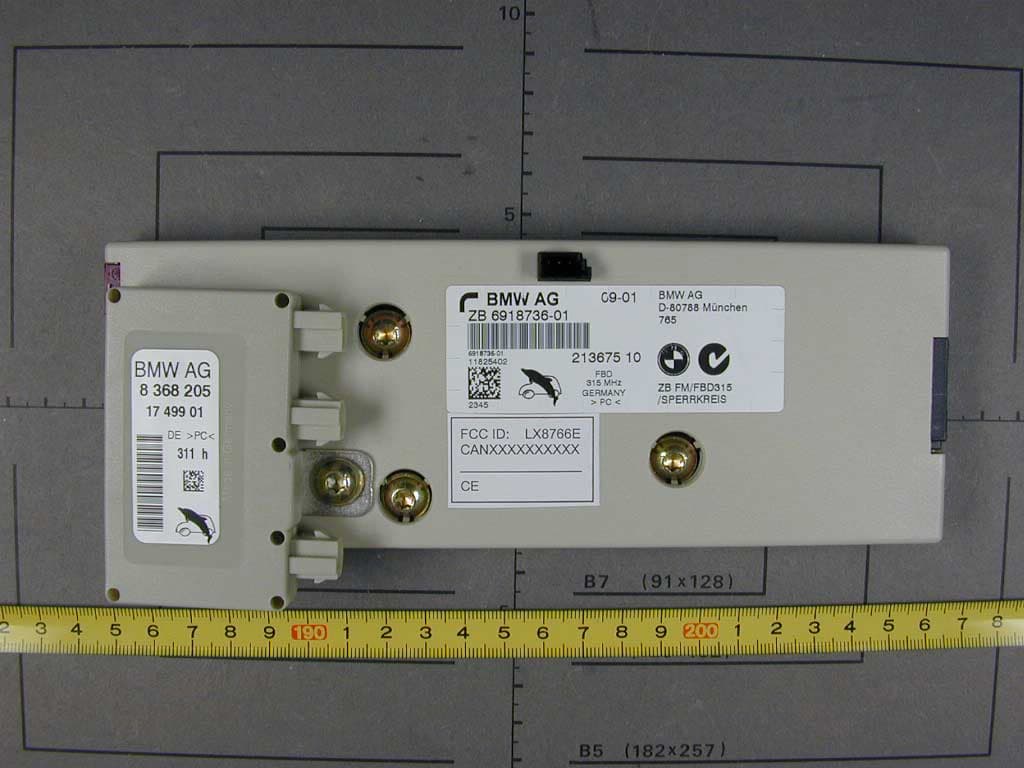
LX8766E
Feb 15, 2002Security Receiver
Equipment Class
CYY - Communications Receiver used w/Pt 15 Transmitter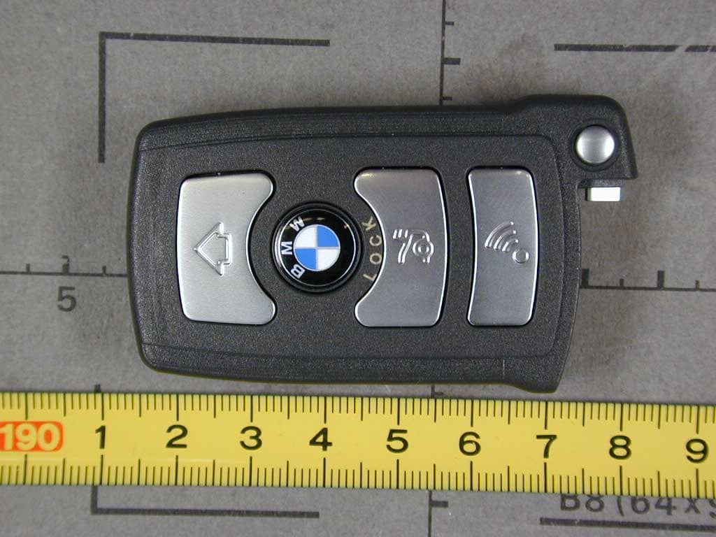
LX8766S
Feb 06, 2002Automotive Remote
Equipment Class
DSC - Part 15 Security/Remote Control Transmitter