LX8PGSAutomotive Inductive Comfort Access System
Bayerische Motoren Werke AG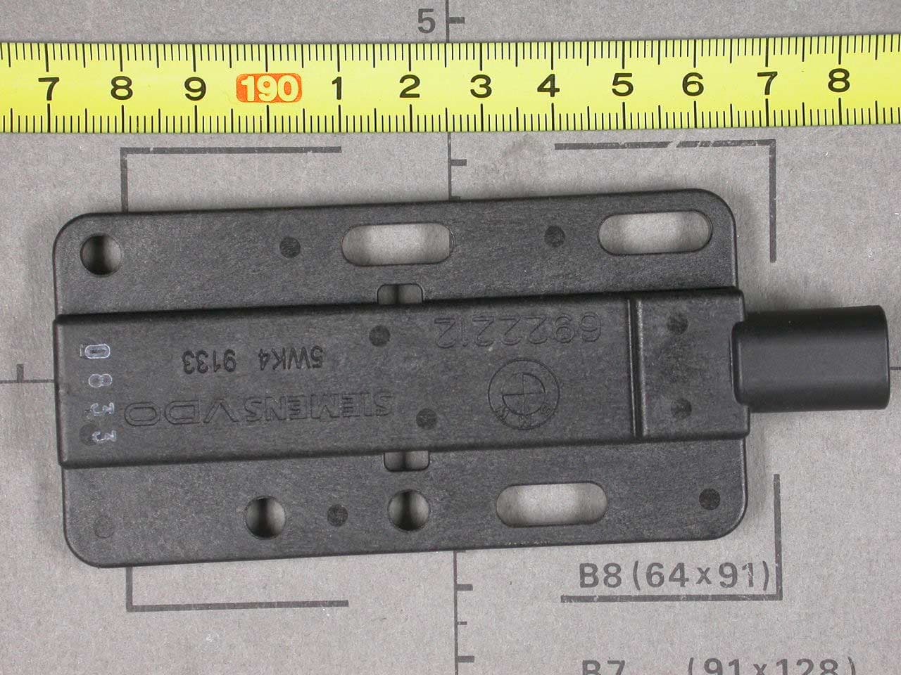
Click to zoom
Application Details
- Equipment Class
- DCD - Part 15 Low Power Transmitter Below 1705 kHz
- Date of Grant
- May 23, 2004
- Application Purpose
- Original Equipment
- Date of Application
- May 23, 2004
- Equipment Note
- Automotive Inductive Comfort Access System
- Frequency Range
- 0.12500000 - 0.12500000
- Company
- Bayerische Motoren Werke AG
- Country
- Germany
Documents & Files
Document Text
Text extracted from the exhibit documents filed with the FCC. Open a document above to read the original.
Users Manual
BMW_PGS2_E8x_Homolog_e.doc Page 1 / 5 SV C BC P2 HW Pase 01.03.2004 CONFIDENTIAL H.Schmittschmitt Functional Description / User Manual for SIEMENS VDO Comfort Access System Type PGS2 5WK4 9135 BMW_PGS2_E8x_Homolog_e.doc Page 2 / 5 SV C BC P2 HW Pase 01.03.2004 CONFIDENTIAL H.Schmittschmitt 1. Functional Description - Comfort Access System (CA) 1.1 General functional description The CA-system enables convenient utilization of the vehicle. To use the vehicle, the driver only needs to take the key along with him/her. The vehicle communicates with the system inductively via antennas. These antennas are located in the rear bumper, in the trunk, of the backlite shelf and in the interior. These antennas are driven inductively with a frequency of 125 kHz. The system's range is limited in a defined fashion by damping the body sheet metal. In the vehicle interior, the ranges of the various antennas overlap, which enables location of the key. 1.2 Passive access control Controlled by TAGE (outside door handles electronic) 1.3 Passive Go (start/stop) The system provides the function which enables starting/stopping the engine without key actuation. The prerequisite for starting the vehicle is a key allocated to the vehicle, which is taken along by the user and is clearly inside the vehicle. By actuating the starting device, the driver starts the identification process, i.e. the PGS control unit issues a request for a valid key inside the vehicle. The key returns an appropriate response to the PGS control unit. In case of successful identification of the key, the vehicle is started and the immobilizer is deactivated. 2. List of variants 5WK4 9135 PGS2 - control unit 5WK4 9132 interior antennas / trunk antenna 5WK4 9133 bumper antenna BMW_PGS2_E8x_Homolog_e.doc Page 3 / 5 SV C BC P2 HW Pase 01.03.2004 CONFIDENTIAL H.Schmittschmitt A1 A2A3A4 TAGE_FT TAGE_BFT PGS2 B M W E 8 x A2 LF LF PGS2 TAGE RF ID- Geber 3. Operating range of the inductive field (LF) A1 - A2 interior antennas A3 trunk antenna A4 bumper antenna 4. Technical parameters Carrier frequency 125kHz Band width 123,75 kHz - 126,25 kHz Field strength < 42 dBμA/m at 10m Type of modulation 100% ASK Method of frequency generation digital sinus generator Number of channels 1 Baud rate 4 kBd Power supply 14 Volt Type of battery Car battery inductive Transmission range < 2m BMW_PGS2_E8x_Homolog_e.doc Page 4 / 5 SV C BC P2 HW Pase 01.03.2004 CONFIDENTIAL H.Schmittschmitt 5. Typical usage pattern 27 start / stop operations in 24 hours (10.000 operations / year) with a typical transmission duration of 39 milliseconds. Transmitter ON 1,053 seconds / 24 hours Transmitter OFF 86.398,95 seconds / 24 hours Duty Cycle: T ON / T (ON+OFF) x 100% = 1,053 / 86.399 x 100 % = 0,0012 % 6. Block diagram of CA System 7. Label Design 41mm 59 mm CA Master CAS2 Control unit PGS2 LF antennas 2 x interior LF antenna 1 x bumper LF antenna 1 x trunk BMW_PGS2_E8x_Homolog_e.doc Page 5 / 5 SV C BC P2 HW Pase 01.03.2004 CONFIDENTIAL H.Schmittschmitt 7.1 FCC Declaration FCC ID LX8PGS This device complies with part 15 of the FCC Rules. Operation is subject to the following two conditions: (1) This device may not cause harmful interference, and (2) this device must accept interference received, including interference that may cause undesired operation. 8. Power up of test samples The test setup consists of the following components: • Control unit: PGS2; 5WK4 9135 • Wiring harness: Control unit ↔ bumper antenna and power supply • Antennas: 1 bumper antenna 5WK4 9133 • Power Supply: 14VDC or car battery (not supplied) The bumper antenna will represent the max. allowed inductive load, which the control unit can supply. 8.1 Test configuration and operation Connect the wiring harness to the control and the bumper antenna. More precise allocation of connector - socket is not necessary, as all connections are mechanical or color-coded. The entire test setup is connected to power via the two banana jacks on the wiring harness. Banana jack, red = 14VDC or car battery Banana jack, blue = GND (ground) The power consumption in case of operation amounts to max. 10A. If the power supply is connected the control unit begins to operate. The connected antenna will transmit the carrier frequency with a duration of approximately 40ms at intervals of 500ms. The transmitter power of the control unit is adjust by 100%. This procedure does not correspond to the standard mode of operation! This procedure is only used to simplify emission measurements.
Cover Letter(s)
Request for Confidentiality 11 May 2004 PHOENIX TEST-LAB GmbH Königswinkel 10 D32825 Blomberg Germany RE: Certification Application FCC ID: LX8PGS Please be advised that the following information is to be held confidential on behalf of BAYERISCHE MOTOREN WERKE AG: • Schematics • Block Diagram • Technical Description The application contains technical information which BAYERISCHE MOTOREN WERKE AG deems to be trade secrets and proprietary. If made public, the information might be used to the disadvantage of the applicant in the market place. Thank you for your attention to this matter.
External Photos
FCC ID LX8PGS Front of Control-unit FCC ID LX8PGS Rear of Control-unit FCC ID LX8PGS Antenna-unit top view
ID Label/Location Info
FCC ID LX8PGS This device complies with Part 15 of the FCC rules. Operation is subject to the following two conditions: (1) this device may not cause harmful interference and (2) this device must accept any interference received, including interference that may cause undesired operation.
Internal Photos
FCC ID LX8PGS Top view of printed board (Control-unit) FCC ID LX8PGS Bottom view of printed board (Control-unit)
Test Report
EMV-Pr ̧fzentrum EMI/EMC-Testcenter FCC-ID: Test Report No. 50217-40229 Page 1 of 17 Pages Straubing, 20 April 2004 T E S T - R E P O R T No. 50217-40229-1 for PGS2 Transceiver for Car-Immobilizer Applicant: Bayerische Motoren Werke AG Test Specification: FCC Code of Federal Regulations, CFR 47, Part 15, Section 15.209 Note: The test data of this report relate only to the individual item which has been tested. This report shall not be reproduced except in full extent without the written approval of the testing laboratory. EMV-Pr ̧fzentrum EMI/EMC-Testcenter FCC-ID: Test Report No. 50217-40229 Page 2 of 17 Pages Table of Contents 1. Administrative Data.....................................................................................3 2. Identification of Test Laboratory .................................................................4 3. Operation Mode of EUT..............................................................................5 4. Configuration ..............................................................................................6 5. Measuring Methods ....................................................................................7 5.1. Radiated Emission Measurement 9 kHz ñ 30 MHz ..............................7 5.2. Field Strength of Emissions, Prescans in a fully-anechoic Room....................................................................................................8 5.3. Radiated Emission Measurement at Open Area Test Site ...................9 6. Photographs Taken During Testing ..........................................................10 7. List of Measurements ...............................................................................13 8. Referenced Regulations ...........................................................................16 Charts taken during testing ...............................................................................17 EMV-Pr ̧fzentrum EMI/EMC-Testcenter FCC-ID: Test Report No. 50217-40229 Page 3 of 17 Pages 1. Administrative Data Test item (EUT) Type designation PGS2 Serial number(s): 5WK4 9135, 5WK4 9133 Type of equipment: Transceiver for Car-Immobilizer Parts/accessories: Control unit, Antenna FCC-ID: Technical data Frequency range 123.75 ñ 126.25 kHz Operational frequencies 125 kHz Type of modulation 10K0A1D Pulse frequency N/A Pulse width N/A Antenna Bumper antenna Power supply 12 V regulated lead acid battery Applicant: (full address) Bayerische Motoren Werke AG BMW Haus Pertuelring 130 D 80788 M ̧nchen Germany Contract identification: --- Contact person: Mr. Richard Hochleitner Manufacturer: Siemens VDO AG Application details Receipt of EUT: 2 April 2004 Date of test: April 2004 Note: Responsible for testing: Martin Steindl Responsible for test report: Martin Steindl EMV-Pr ̧fzentrum EMI/EMC-Testcenter FCC-ID: Test Report No. 50217-40229 Page 4 of 17 Pages 2. Identification of Test Laboratory DETAILS OF THE TEST LABORATORY COMPANY NAME: Senton GmbH EMI/EMC Test Center ADDRESS: Aeussere Fruehlingsstrasse 45 D-94315 Straubing Germany LABORATORY ACCREDITATION: DAR-Registration No. TTI-P-G 062/94-01 FCC TEST SITE LISTING 90926 INDUSTRY CANADA TEST SITE REGISTRATION IC 3050 NAME FOR CONTACT PURPOSES: Mr. Johann Roidt TELEPHONE: (+49) (0)9421 5522-0 FAX: (+49) (0)9421 5522-99 PERSONNEL INVOLVED IN THIS TEST REPORT LABORATORY MANAGER: Mr. Johann Roidt RESPONSIBLE FOR TESTING: Mr. Martin Steindl RESPONSIBLE FOR TEST REPORT: Mr. Martin Steindl SUMMARY OF TEST RESULTS The tested sample complies with the requirements set forth in the Code of Regulations CFR 47, Part 15, Section 15.209 EMV-Pr ̧fzentrum EMI/EMC-Testcenter FCC-ID: Test Report No. 50217-40229 Page 5 of 17 Pages 3. Operation Mode of EUT Transmitting continiously EMV-Pr ̧fzentrum EMI/EMC-Testcenter FCC-ID: Test Report No. 50217-40229 Page 6 of 17 Pages 4. Configuration Configuration of the EUT Not applicable Cables connected to the EUT Description Classification Cable type Maximum cable length DC-supply DC power Unshielded > 3m Antenna-supply signal/control port Unshielded 1.9 m Peripheral devices connected to the EUT Not applicable EMV-Pr ̧fzentrum EMI/EMC-Testcenter FCC-ID: Test Report No. 50217-40229 Page 7 of 17 Pages 5. Measuring Methods 5.1. Radiated Emission Measurement 9 kHz ñ 30 MHz Rules and Specifications: Sections 15.109 & 15.209 Guide: ANSI C63.4 1997 Measurement Procedure: Radiated emissions in the frequency range 9 kHz ñ 30 MHz were measured initially at a distance of 3 meters. A prescan at 3 meter distance were performed in a shielded room with the detector of the spectrum analyzer or EMI Receiver set to peak. Hand-held or body-worn devices are rotated through three orthogonal axes to determine which attitude and configuration produces the highest emission relative to the limit and therefore shall be used for final testing. Final measurement is then performed at 30 meter distance. In case the regulation requires testing at other distances, the result will be extrapolated. The extrapolation factor is determined by making a second measurement at 10 meter distance. In cases of very low emissions measurements are performed at shorter distances and results are extrapolated to the required distance. The provisions of 15.31 (d) apply. According to section 15.209 (d) final measurementis performed with the detector set to Quasi Peak except for the frequency bands 9 ñ 90 kHz and 110 ñ 490 kHz where average detector is employed. EMI Receiver EUT 30 m test distance Test instruments used: No. Type Model Serial Number Manufacturer 01 Test receiver ESH 3 880112/032 Rohde & Schwarz 02 Loop antenna HFH2-Z2 882964/1 Rohde & Schwarz 03 Open Field Test Site No. 1 N/A Senton EMV-Pr ̧fzentrum EMI/EMC-Testcenter FCC-ID: Test Report No. 50217-40229 Page 8 of 17 Pages 5.2. Field Strength of Emissions, Prescans in a fully-anechoic Room Rules and Specifications: Sections 15.109 & 15.209 Guide: ANSI C63.4 1997 Measurement Procedure: Radiated emissions are measured over the …
Text truncated - open the document above for the full version.
Test Setup Photos
EMV-Pr ̧fzentrum EMI/EMC-Testcenter FCC-ID: Test Report No. 50217-40229 Page 11 of 17 Pages Test setup for radiated emission measurement (fully anechoic room) EMV-Pr ̧fzentrum EMI/EMC-Testcenter FCC-ID: Test Report No. 50217-40229 Page 12 of 17 Pages Test setup for radiated emission measurement (open area test-side
Contact Information
Applicant
Richard Hochleitner
Technical Contact
Senton GmbHJohann Roidt
[email protected]+49 9421 55 22 13
Aeussere Fruehlingstrasse 45 · Straubing · Germany
Non-Technical Contact
Senton GmbHJohann Roidt
[email protected]+49 9421 55 22 13
Test Firm
TUV SUD Product Service GmbH PS-EMC-STRRainer Heller
Technical Specifications
| # | Rule Parts | Frequency Range | Power Output |
|---|---|---|---|
| 1 | 15C | 0.125 MHz - 0.125 MHz | - |
Other Applications from Bayerische Motoren Werke AG
LX8CAS93
Nov 19, 2006Comfort Access System
Equipment Class
DCD - Part 15 Low Power Transmitter Below 1705 kHz
LX8CAS89X
May 16, 2004Transceiver for Car Immobilizer
Equipment Class
DCD - Part 15 Low Power Transmitter Below 1705 kHz
LX8CAS2
Dec 17, 2002Inductive Reader
Equipment Class
DCD - Part 15 Low Power Transmitter Below 1705 kHz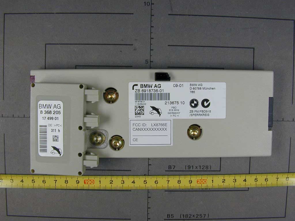
LX8766E
Feb 15, 2002Security Receiver
Equipment Class
CYY - Communications Receiver used w/Pt 15 Transmitter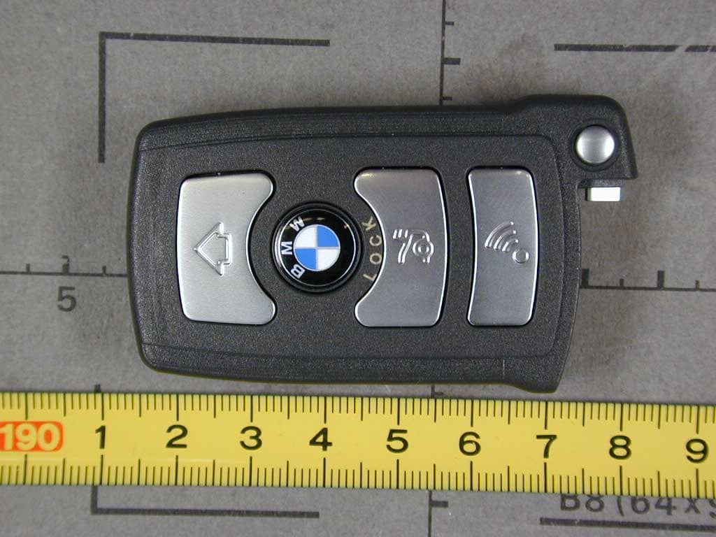
LX8766S
Feb 06, 2002Automotive Remote
Equipment Class
DSC - Part 15 Security/Remote Control Transmitter