LX8766ESecurity Receiver
Bayerische Motoren Werke AG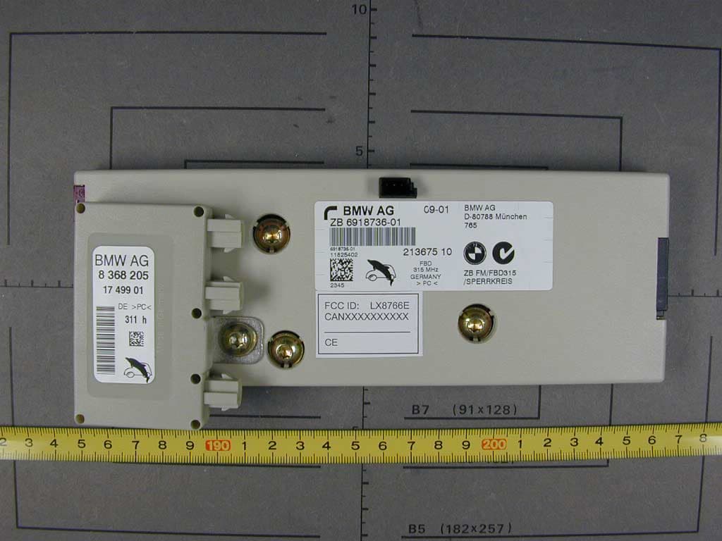
Click to zoom
Application Details
- Equipment Class
- CYY - Communications Receiver used w/Pt 15 Transmitter
- Date of Grant
- Feb 15, 2002
- Application Purpose
- Original Equipment
- Date of Application
- Feb 15, 2002
- Equipment Note
- Security Receiver
- Frequency Range
- 315.00000000 - 315.00000000
- Company
- Bayerische Motoren Werke AG
- Country
- Germany
Documents & Files
Document Text
Text extracted from the exhibit documents filed with the FCC. Open a document above to read the original.
Users Manual
Opening and closing 32 Opening and closing Key/remote control 1The Key Memory functions are controlled by the two remote control units with their integrated keys, refer to page 57. The color-coded decals that you received when taking delivery of your vehicle can be used to identify the individual remote control units Each remote control unit is equipped with an extended-life battery which is automatically recharged in the ignition lock each time you drive the vehicle. If you have any remote control units that are not being used on a regular basis, you should therefore remember to recharge these units by using them to drive the vehicle for an extended period at least once a year, refer to page 33.< 2Spare key for storage in a safe place, such as in your wallet. This key is not intended for constant use 3Adapter for spare key The adapter can be used to store the spare key. It can be stored in the place provided within the luggage compartment lid- mounted onboard tool kit to ensure that it will always be available, refer to page 187. You can find more detailed information on using the adapter in the section Using the spare key adapter. Removing the key from the remote control unit Press the button 1 to release the key. With the integrated key you can unlock and lock the following: >the storage compartment under the front armrest >the driver's door >the luggage compartment lid. Within this storage compartment you will also find the switch for locking the luggage compartment lid separately, refer to page 37. If you lock the storage compartment and only turn over the remote control, for valet parking, etc., no access is possible via the luggage compartment lid. Using the spare key adapter You will need the adapter to activate the ignition and to start the vehicle with the spare key. ba.book Seite 32 Dienstag, 29. Januar 2002 4:03 16 At a glance Controls Driving tips Communications Navigation Entertainment Mobility Reference 33 Slide up the cover 1 and insert the spare key 2 in the adapter. Close the cover and insert the adapter in the ignition lock. Central locking system The concept The central locking system is ready for operation whenever the driver's door is closed. This simultaneously engages and releases the locks on the following: >Doors >Luggage compartment lid >Fuel filler door. The central locking system can be oper- ated from the outside >via the remote control >via the driver's door lock and from inside via the button for the central locking system. When the system is locked from inside, the fuel filler door remains unlocked, refer to page 35. The anti-theft system is automatically acti- vated whenever you activate the central locking system from outside the vehicle. The alarm system is armed/disarmed at the same time. In the event of an accident, the central locking system unlocks automatically – only those doors which were not locked sepa- rately with the safety lock buttons, refer to page 36. In addition, the hazard warning flashers and interior lamps come on. Opening and closing – from outside Using the remote control When you engage/release the vehicle's locks, you simultaneously activate/deacti- vate the anti-theft system, arm/disarm the alarm system and switch the interior lamps on/off. In addition, the remote control offers you another function: >Panic mode In case of danger, you can trigger an alarm. You can have various confirmation signals programmed into the system to verify that the vehicle has been locked securely.< Remote control 1To unlock, convenience opening mode and alarm system 2To lock and secure, switch off tilt alarm sensor and interior motion sensor, switch on interior lamps and door-mounted prox- imity lamps 3To open the luggage compartment lid 4To switch on interior lamps, activate panic mode Because any persons or animals left unattended in a parked vehicle could lock the doors from the inside, you should always keep the remote control unit with you; this precaution ensures that you will remain able to unlock the vehicle from the outside at all times.< When it is no longer possible to lock the vehicle via the remote control, the battery is discharged. Use this remote control unit during an extended drive; this will recharge the battery, refer to page 32. In the event of a system malfunction, please contact your BMW center, which is also your source for replacement keys.< ba.book Seite 33 Dienstag, 29. Januar 2002 4:03 16 Opening and closing 34 Unlocking the vehicle Press button 1. The interior lamps and the door-mounted proximity lamps come on. Press the button once to unlock the driver's door only; press a second time to unlock all remaining doors as well as the luggage compartment lid and the fuel filler door. Convenience opening mode Maintain pressure on button 1. The windows and the sliding/tilt sunroof open. The sliding/tilt sunroof will not be retracted if it is already in its raised position. Locking and securing Press button 2. Switching off the tilt alarm sensor and interior motion sensor Press button 2 again immedi- ately after locking. For more detailed information, refer to page 39. Switching on interior lamps and door-mounted proximity lamps With the vehicle locked, press button 2. Switching on the interior lamps Press button 4. You can also use this function to locate your vehicle in parking garages etc. Panic mode By pressing and holding button 4for more than approx. two seconds, you can trigger the alarm system in response to any impending danger. To switch off the alarm: press any of the buttons. Opening the luggage compartment lid Press button 3for approx. one second. The luggage compartment lid opens, regardless of whether it was previously locked or unlocked. During opening the luggage compart- ment lid pivots upward and to the rear. Ensure that adequate clearance is available before opening. To avoid being inadvertently locked out, never lay the remote control unit down in the luggage compartment. If the luggage compartment lid was lo…
Text truncated - open the document above for the full version.
Cover Letter(s)
Request for Confidentiality 06 February 2002 American Telecommunications Certification Body, Inc. 6731 Whittier Avenue Suite C110 McLean, VA 22101 RE: Certification Application FCC ID: LX8766E Please be advised that the following information is to be held confidential and behalf of Bayerische Motoren Werke AG: • Description of operation • Schematic Diagrams • Block Diagram The application contains technical information which Bayerische Motoren Werke AG deems to be trade secrets and proprietary. If made public, the information might be used to the disadvantage of the applicant in the market place. Thank you for your attention to this matter. Johann Roidt
External Photos
FCC ID LX8765S FCC ID: LX8766E External Photos FCC ID LX8765S
ID Label/Location Info
FCC ID LX8765S FCC ID: LX8766E Label Information
Internal Photos
FCC ID LX8765S FCC ID: LX8766E Internal Photos FCC ID LX8765S FCC ID LX8765S FCC ID LX8765S FCC ID LX8765S
Test Report
EMV-Pr ̧fzentrum EMI/EMC-Testcenter Page 1 of 34 Pages Straubing, 06 February 2002 T E S T - R E P O R T No. 50217-20081-2 for FZV Receiver Typ 765 315 MHz Remote Control Receiver Module Applicant: Bayerische Motoren Werke AG Purpose of testing: To show compliance with FCC Code of Federal Regulations, Part 15 Subpart B Class B Industry Canada Radio Standards Specification RSS-210 Issue 2, Section 6.1 (Category I Equipment) Note: The test data of this report relate only to the individual item which has been tested. This report shall not be reproduced except in full extent without the written approval of the testing laboratory. EMV-Pr ̧fzentrum EMI/EMC-Testcenter Test report for FCC Part 15 Test Report No. 50217-20081-2 Page 2 of 25 Pages Table of Contents 1. Administrative Data.................................................................................... 3 2. Identification of Test Laboratory................................................................. 4 3. Summary of Test Results........................................................................... 5 4. Operation Mode of EUT ............................................................................. 6 5. Configuration of EUT and Peripheral Devices ........................................... 7 6. Measuring Methods ................................................................................... 8 6.1. Conducted Emission 0.45 MHz - 30 MHz (ß15.107) / RSS-210 Section 7.4).......................................................................... 8 6.2. Radiated Emission 30 MHz - 1 GHz (FCC ß15.109 / RSS-210 Section 7.3)........................................................................ 10 6.3. Radiated Emission 1 GHz - 4.5 GHz (FCC ß15.109 / RSS-210 Sections 7.3) ...................................................................... 12 7. Equipment List ......................................................................................... 14 8. Photographs Taken During Testing ......................................................... 16 9. List of Measurements............................................................................... 19 9.1. List of Measurements According To FCC Part 15 Subpart B........................................................................................... 20 9.2. List of Measurements According To Industry Canada RSS-210 ............................................................................................ 21 10. Referenced Regulations .......................................................................... 22 11. Test Results ............................................................................................. 23 EMV-Pr ̧fzentrum EMI/EMC-Testcenter Test report for FCC Part 15 Test Report No. 50217-20081-2 Page 3 of 25 Pages 1. Administrative Data Equipment Under Test (EUT): FZV Receiver Typ 765 315 MHz Serial number(s): 0001 Type of equipment: Remote Control Receiver Module Parts/accessories: FCC-ID: Applicant: Bayerische Motoren Werke AG (full address) Petuelring 130 D-80788 Muenchen Contract identification: --- Contact person: Mr. Hochleitner Manufacturer: Bayerische Motoren Werke AG Receipt of EUT: 04 February 2002 Date of test: 05 February 2002 Note: --- Responsible for testing: Johann Roidt Responsible for test report: Johann Roidt EMV-Pr ̧fzentrum EMI/EMC-Testcenter Test report for FCC Part 15 Test Report No. 50217-20081-2 Page 4 of 25 Pages 2. Identification of Test Laboratory Test Laboratory: Senton GmbH EMI/EMC Test Center (full address): Aeussere Fruehlingstrasse 45 D-94315 Straubing Germany Contact person: Mr. Johann Roidt Communication: Telephone (+49) 0 94 21 / 55 22-0 Fax (+49) 0 94 21 / 55 22-99 eMail: [email protected] FCC registration number: 90926 Industry Canada file number: IC 3050 EMV-Pr ̧fzentrum EMI/EMC-Testcenter Test report for FCC Part 15 Test Report No. 50217-20081-2 Page 5 of 25 Pages 3. Summary of Test Results The tested sample complies with the requirements set forth in the FCC Part 15 Subpart B Class B of the Federal Communication Commission (FCC). and the Radio Standards Specification RSS-210 Issue 2, Section 6.1 for Low Power Licence-Exempt Radiocommuniction Devices of Industry Canada. Johann Roidt Technical Manager EMV-Pr ̧fzentrum EMI/EMC-Testcenter Test report for FCC Part 15 Test Report No. 50217-20081-2 Page 6 of 25 Pages 4. Operation Mode of EUT Not applicable EMV-Pr ̧fzentrum EMI/EMC-Testcenter Test report for FCC Part 15 Test Report No. 50217-20081-2 Page 7 of 25 Pages 5. Configuration of EUT and Peripheral Devices Configuration of cables of EUT Not applicable Configuration of peripheral devices connected to EUT Not applicable EMV-Pr ̧fzentrum EMI/EMC-Testcenter Test report for FCC Part 15 Test Report No. 50217-20081-2 Page 8 of 25 Pages 6. Measuring Methods 6.1. Conducted Emission 0.45 MHz - 30 MHz (ß15.107) / RSS-210 Section 7.4) Conducted emissions were measured in the frequency range 0.45 MHz to 30 MHz. The bandwidth of the EMI-Receiver was set to 9 kHz and the detector-function was set to CISPR quasi-peak. The test setup was made in accordance with ANSI C63.4-1992. Measurements were performed on phase and neutral lines of the power-cords of the tested system. Preliminary scans were taken with the detector-function of the EMI- receiver set to peak to determine the conducted EMI-profile of the EUT. At the final test the cables and equipment were placed and moved within the range of positions likely to find their maximum emissions. See figure 1 for the measurement setup. Test equipment used (see equipment list for details): 04, 22, 23, 60, 63 EMV-Pr ̧fzentrum EMI/EMC-Testcenter Test report for FCC Part 15 Test Report No. 50217-20081-2 Page 9 of 25 Pages 9 10 11 5 8 2 7 4 1 3 6 Figure 1: Example of measurement setup for conducted emission test 1 EUT 8 LISN for EUT 2 Monitor 9 LISN for peripheral device(s) 3 Keyboard 10 Test receiver 4 Mouse 11 Shielded room 5 Parallel Printer 6 Serial Printer 7 Wooden table EMV-Pr ̧fzentrum …
Text truncated - open the document above for the full version.
Test Setup Photos
EMV-Pr ̧fzentrum EMI/EMC-Testcenter Test report for FCC Part 15 Test Report No. 50217-20081-2 Page 17 of 25 Pages Photos No. 8.1 - 8.2 Test setup for radiated emission pre-test 30 MHz - 1 GHz (semi anechoic room) EMV-Pr ̧fzentrum EMI/EMC-Testcenter Test report for FCC Part 15 Test Report No. 50217-20081-2 Page 18 of 25 Pages Photos No. 8.3 - 8.4 Test setup for radiated emission final test 30 MHz - 1 GHz (open area test site)
Contact Information
Applicant
Richard Hochleitner
Technical Contact
Senton GmbHJohann Roidt
[email protected]49 9421 55 22 13
Aeussere Fruehlingstrasse 45 · Straubing · Germany
Non-Technical Contact
Senton GmbHJohann Roidt
[email protected]49 9421 55 22 13
Test Firm
TUV SUD Product Service GmbH PS-EMC-STRRainer Heller
Technical Specifications
| # | Rule Parts | Frequency Range | Power Output |
|---|---|---|---|
| 1 | 15B | 315 MHz - 315 MHz | - |
Other Applications from Bayerische Motoren Werke AG
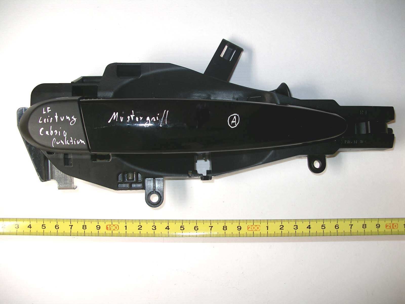
LX8CAS93
Nov 19, 2006Comfort Access System
Equipment Class
DCD - Part 15 Low Power Transmitter Below 1705 kHz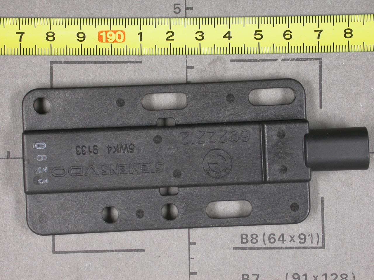
LX8PGS
May 23, 2004Automotive Inductive Comfort Access System
Equipment Class
DCD - Part 15 Low Power Transmitter Below 1705 kHz
LX8CAS89X
May 16, 2004Transceiver for Car Immobilizer
Equipment Class
DCD - Part 15 Low Power Transmitter Below 1705 kHz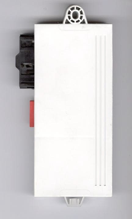
LX8CAS2
Dec 17, 2002Inductive Reader
Equipment Class
DCD - Part 15 Low Power Transmitter Below 1705 kHz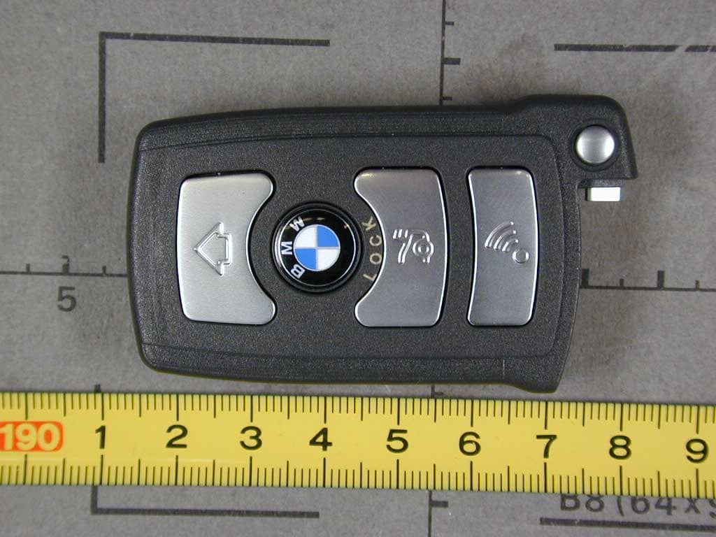
LX8766S
Feb 06, 2002Automotive Remote
Equipment Class
DSC - Part 15 Security/Remote Control Transmitter