LYHVAS5053Car Diagnostic System with Bluetooth
Siemens AG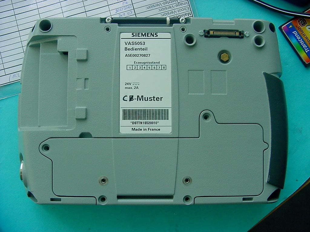
Click to zoom
Application Details
- Equipment Class
- DSS - Part 15 Spread Spectrum Transmitter
- Date of Grant
- Aug 08, 2004
- Application Purpose
- Original Equipment
- Date of Application
- Aug 08, 2004
- Equipment Note
- Car Diagnostic System with Bluetooth
- Frequency Range
- 2402.00000000 - 2480.00000000
- Company
- Siemens AG
- Country
- Germany
Documents & Files
Document Text
Text extracted from the exhibit documents filed with the FCC. Open a document above to read the original.
Users Manual
Vehicle Diagnostic and Service Informations system VAS 5053 Ausgabestand: 06.08.04, A01.3 Operating Manual A01.308/04 IBR 339 IMPORTANT SAFETY INSTRUCTIONS Operating Manual VAS 5053 A01.3 08/04 All rights reserved. iA5E00310438 VA S 5 05 3 VAS 5051B VAS 5051 VAS 5052 Safety Instructions Meaning of symbols The safety instructions in the Operating Manual, the Startup/Unpacking Instructions or in other documentation provided, on screen displays on the tester during operation and on the products themselves use symbols with the following meanings: The WARNING symbol warrants particular attention for your safety. The Caution symbol tells you that if the information is ignored, damage to the vehicle and/or the tester could result (e.g.: Ensure that the touchscreen is not touched with sharp, edged objects). A Note symbol contains other, special instructions for using the device, and related information. Warning! Text with this symbol contains information for your safety and how you can reduce the risk of severe or fatal injury. Caution! Text with this symbol contains information about how you can avoid damage to the vehi- cle and the tester. Note Text with this symbol contains additional, useful information. Note The general safety instructions are listed in the following. Further instructions are to be found in the Operating Manual. Therefore read the Operating Manual before use. Safety instructions may also appear on the screen of the tester. Follow all the instruc- tions displayed. IMPORTANT SAFETY INSTRUCTIONS Operating Manual VAS 5053 A01.3 08/04 All rights reserved. iiA5E00310438 VA S 5 05 3 VAS 5051B VAS 5051 VAS 5052 IMPORTANT SAFETY INSTRUCTIONS 1. Warning! Read all instructions. 2. Warning! Do not operate equipment with a damaged cord or if the equipment has been damaged - until it has been examined by a qualified serviceman. 3. Warning! Do not let cord hang over edge of table, bench or counter, or come in contact with hot manifolds or moving fan blades. 4. Warning! An extension cord is not allowed. For testing use only specified cables. 5. Warning! Always unplug equipment from electrical outlet when not in use. Never yank cord to pull plug from outlet. Grasp plug and pull to disconnect. 6. Warning! To protect against risk of fire, do not operate equipment in the vicinity of open contai- ners of fuel (gasoline). Risk of explosion This equipment has internal arcing or sparking parts wich should not be exposed to flammable vapour. This equipment should be located at least 460 mm (18 inches) above the floor. IMPORTANT SAFETY INSTRUCTIONS Operating Manual VAS 5053 A01.3 08/04 All rights reserved. iiiA5E00310438 VA S 5 05 3 VAS 5051B VAS 5051 VAS 5052 7. Warning! Adequate ventilation should be provided when working on operating combustion engi- nes. 8. Warning! Use only as described in this manual. Use only manufactures’s recommended attach- ments. 9. Warning! When connected to electrical power supply, the devices correspond to protection class 1 and are fitted with a safety-tested power cable. They may only be connected to electrical networks with an earthed protective conductor (TN networks) or electrical out- lets with earthed protective conductors. 10. Warning! All measurement probes shall be used within their specifications and as described within these instructions. All measurement clamps shall be used on appropriate insu- lated wiring. Do not conduct measurement, if the wiring is damaged. 11. Warning! During test drives, secure the tester with a strap on the vehicle's back seatand connect it to the vehicle using the diagnostic cable. A second person must operate the tester from the back seat. Operation from the front seat is too dangerous, e.g. in the event of airbag activation. VAS 5051 To supply the VAS 5051 with power from the vehicle battery, use only the 3 m diagnostic cable. IMPORTANT SAFETY INSTRUCTIONS Operating Manual VAS 5053 A01.3 08/04 All rights reserved. ivA5E00310438 VA S 5 05 3 VAS 5051B VAS 5051 VAS 5052 12. Warning! Electrical ignition systems carry currents of up to approx. 30 kV. Observe general safety guidelines for workshops at all times. 13. Warning! If you open the tester or its accessories without authorisation or carry out improper alte- rations to them, considerable risk to you and to the device may result. 14. Caution! Fluctuations and deviations in the power supply beyond the permitted range of toler- ance can lead to malfunctions and damage. 15. Caution! VAS 5051 - changing fuse For inline current measurement with the VAS 5051, only a replacement fuse of the same type and same amperage may be installed in order to avoid risks of fire and to protect the device. To order original parts, refer to the corresponding chapters of the Operating Manual. 16. Caution! when connecting other vehicle makes The VAS 505x diagnostic devices were developed for vehicles from the Volkswagen group. If the tester is connected directly to vehicles from other manufacturers, damage to the vehicle could result. Therefore if vehicles of other makes are to be tested using the general OBD functions in the self-diagnosis application, the OBD adapter cable VAS 5052/16 needs to be con- nected between the diagnostic cable and the diagnostic connection on the vehicle (with fewer cable connections). 17. Caution! •Battery change may only be performed by qualified personel. •Do not short out the battery. •Do not incinerate the battery. •Dispose/recycle the battery in accordance with local environmental regulations. IMPORTANT SAFETY INSTRUCTIONS Operating Manual VAS 5053 A01.3 08/04 All rights reserved. vA5E00310438 VA S 5 05 3 VAS 5051B VAS 5051 VAS 5052 Warnings because of built-in Bluetooth transceiver 18. Warning! FCC 15.105: This equipment has been tested and found to comply with the limits for a Class B digital device, pursuant to Part 15 of the FCC Rules. These limits are designed to provide reasonable protection against harmful interference in a residential installa- tion. This equip…
Text truncated - open the document above for the full version.
External Photos
SRD-Testreport CETECOM ICT Services GmbH Saarbruecken, Germany Test report No.: 2-3577-01-07/04Date: 2004-06-18Page 53 of 65 SRD-Testreport CETECOM ICT Services GmbH Saarbruecken, Germany Test report No.: 2-3577-01-07/04Date: 2004-06-18Page 54 of 65 SRD-Testreport CETECOM ICT Services GmbH Saarbruecken, Germany Test report No.: 2-3577-01-07/04Date: 2004-06-18Page 55 of 65
ID Label/Location Info
Siemens AG A&D PT3 SE3 A5E00273126A Typenschild VAS5053 25.11.03 Vogt C D E A B 1234 PROPRIETARY DATAALL RIGHTS RESERVED ALS BETRIEBSGEHEIMN IS ANVERTRAUT ALLE RECHTE VORBEHALTEN CONFIADO COMO SECRETO INDUSTRIAL RESERVADOS TODO S LOS DERECHOS Blatt Dok.Typ Ausgangsteil: C75322-A3002-C640 74 x 37 mm 3M Typ 7816 Polyesterfolie ws Schrift : Helvetica Condensed Medium nach DIN 30640 tiefschwarz halbmatt Wischfest nach DIN 53109 / SN 27650 von Dokument Artikel Datum: Urheber: Massstab: Änd.-Nr.: DS:ES: Änd.-Datum: Bearbeiter: Ers. f.: Fab-Gr.: 79A53387 21.07.04 Vogt 1 1 A5E00273126 01 . UL-Zeichen h=8mm nach Angaben von Underwriters Laboratories Inc. siehe auch SN 10790 Grösse ca. 4x4 mm Strichstärke 0,5 mm Schrift im Feld ausgemittelt SIEMENS Made in France 4 SN 66323 Strichstärke 0,5 mm Schrift Helvetica Condensed Medium Höhe = 2mm Schrift A2,5 fett Schrift A2,5 F-Nr. nach SN 01007 mit Zusatz 1) VAS 5053 Bedienteil A5E00270827 Erzeugnisstand DSTTN1SN12345 Symbol für Gleichstrom IEC 5031 n. DIN 30600 Reg.Nr.36 CE-Zeichen h=6mm 7C99 GARAGE EQUIPMENT 1) DSTTN1SN12345 DSTT = Systemnummer VW N1 = SIEMENS Haguenau S = Jahr (z.B. 2004) N = Monat (z.B. November) 12345 = Zählnummer (5 Stellig) 12/24V 2A 1234567 8910 ID:LYHVAS5053 IC:267AA-VAS5053 Schrift A2,5
Internal Photos
SRD-Testreport CETECOM ICT Services GmbH Saarbruecken, Germany Test report No.: 2-3577-01-07/04Date: 2004-06-18Page 56 of 65 SRD-Testreport CETECOM ICT Services GmbH Saarbruecken, Germany Test report No.: 2-3577-01-07/04Date: 2004-06-18Page 57 of 65 SRD-Testreport CETECOM ICT Services GmbH Saarbruecken, Germany Test report No.: 2-3577-01-07/04Date: 2004-06-18Page 58 of 65 SRD-Testreport CETECOM ICT Services GmbH Saarbruecken, Germany Test report No.: 2-3577-01-07/04Date: 2004-06-18Page 59 of 65 SRD-Testreport CETECOM ICT Services GmbH Saarbruecken, Germany Test report No.: 2-3577-01-07/04Date: 2004-06-18Page 60 of 65 SRD-Testreport CETECOM ICT Services GmbH Saarbruecken, Germany Test report No.: 2-3577-01-07/04Date: 2004-06-18Page 61 of 65 SRD-Testreport CETECOM ICT Services GmbH Saarbruecken, Germany Test report No.: 2-3577-01-07/04Date: 2004-06-18Page 62 of 65 SRD-Testreport CETECOM ICT Services GmbH Saarbruecken, Germany Test report No.: 2-3577-01-07/04Date: 2004-06-18Page 63 of 65 SRD-Testreport CETECOM ICT Services GmbH Saarbruecken, Germany Test report No.: 2-3577-01-07/04Date: 2004-06-18Page 64 of 65 SRD-Testreport CETECOM ICT Services GmbH Saarbruecken, Germany Test report No.: 2-3577-01-07/04Date: 2004-06-18Page 65 of 65
RF Exposure Info
CETECOM ICT Services GmbH Untertuerkheimer Str. 6-10, 66117 Saarbruecken, Germany Phone: +49 (0) 681 598-0 Fax: -8475 SAR-Laboratory Phone: +49 (0) 681 598-8454 . As of 2004-06-23 Page 1 of 49 Accredited testing laboratory DAR registration number: TTI-P-G 081/94-D0 Federal Motor Transport Authority (KBA) DAR registration number: KBA-P 00070-97 Test report no. : 2-3577-01-10/04-B Type identification : VAS5053 Test specification : IEEE P1528/D1.2 FCC-ID : LYHVAS5053 IC : 267AAVAS5053 Test specification : CETECOM ICT Services GmbH Test report no.: 2-3577-01-10/04-B As of 2004-06-23 Page 2 of 49 Table of Contents 1 General Information...................................................................................................................................................................................3 1.1 Notes......................................................................................................................................................................................................3 1.1.1 Statement of Compliance........................................................................................................................................................3 1.2 Testing laboratory................................................................................................................................................................................4 1.3 Details of applicant..............................................................................................................................................................................4 1.4 Application details...............................................................................................................................................................................4 1.5 Test item................................................................................................................................................................................................5 1.6 Test specification(s)............................................................................................................................................................................6 1.6.1 RF exposure limits....................................................................................................................................................................6 2 Technical test...............................................................................................................................................................................................7 2.1 Summary of test results......................................................................................................................................................................7 2.2 Test environment.................................................................................................................................................................................7 2.3 Measurement and test set-up.............................................................................................................................................................7 2.4 Measurement system...........................................................................................................................................................................8 2.4.1 System Description...................................................................................................................................................................8 2.4.2 Test environment......................................................................................................................................................................9 2.4.3 Probe description......................................................................................................................................................................9 2.4.4 Phantom description...............................................................................................................................................................10 2.4.5 Device holder description......................................................................................................................................................10 2.4.6 Scanning procedure................................................................................................................................................................11 2.4.7 Spatial Peak SAR Evaluation...............................................................................................................................................12 2.4.8 Data Storage and Evaluation.................................................................................................................................................13 2.4.9 Test equipment utilized..........................................................................................................................................................15 2.4.10 Tissue simulating liquids : dielectric properties................................................................................................................16 2.4.11 Tissue simulating liquids : parameters................................................................................................................................17 2.4.12 Measurement uncertainty evaluation for SAR test...........................................................................................................18 2.4.13 Measurement uncertainty evaluation for system validation............................................................................................19 2.4.14 System validation....................................................................................................................................................................20 2.4.15 Validation procedure............................................…
Text truncated - open the document above for the full version.
RF Exposure Info
CETECOM ICT Services GmbH Untertuerkheimer Str. 6-10, 66117 Saarbruecken, Germany Phone: +49 (0) 681 598-0 Fax: -8475 SAR-Laboratory Phone: +49 (0) 681 598-8454 . As of June 23, 2004 Page 1 of 27 Accredited testing laboratory DAR registration number: TTI-P-G 166/98 Federal Motor Transport Authority (KBA) DAR registration number: KBA-P 00070-97 Calibration data and Phantom information for test report no. 2-3577-01-10/04-B Test specification : CETECOM ICT Services GmbH Calibration Data and Phantom Information; Report No.: 2-3577-01-10/04-B As of June 23, 2004 Page 2 of 27 CETECOM ICT Services GmbH Calibration Data and Phantom Information; Report No.: 2-3577-01-10/04-B As of June 23, 2004 Page 3 of 27 CETECOM ICT Services GmbH Calibration Data and Phantom Information; Report No.: 2-3577-01-10/04-B As of June 23, 2004 Page 4 of 27 CETECOM ICT Services GmbH Calibration Data and Phantom Information; Report No.: 2-3577-01-10/04-B As of June 23, 2004 Page 5 of 27 CETECOM ICT Services GmbH Calibration Data and Phantom Information; Report No.: 2-3577-01-10/04-B As of June 23, 2004 Page 6 of 27 CETECOM ICT Services GmbH Calibration Data and Phantom Information; Report No.: 2-3577-01-10/04-B As of June 23, 2004 Page 7 of 27 CETECOM ICT Services GmbH Calibration Data and Phantom Information; Report No.: 2-3577-01-10/04-B As of June 23, 2004 Page 8 of 27 CETECOM ICT Services GmbH Calibration Data and Phantom Information; Report No.: 2-3577-01-10/04-B As of June 23, 2004 Page 9 of 27 CETECOM ICT Services GmbH Calibration Data and Phantom Information; Report No.: 2-3577-01-10/04-B As of June 23, 2004 Page 10 of 27 CETECOM ICT Services GmbH Calibration Data and Phantom Information; Report No.: 2-3577-01-10/04-B As of June 23, 2004 Page 11 of 27 CETECOM ICT Services GmbH Calibration Data and Phantom Information; Report No.: 2-3577-01-10/04-B As of June 23, 2004 Page 12 of 27 CETECOM ICT Services GmbH Calibration Data and Phantom Information; Report No.: 2-3577-01-10/04-B As of June 23, 2004 Page 13 of 27 CETECOM ICT Services GmbH Calibration Data and Phantom Information; Report No.: 2-3577-01-10/04-B As of June 23, 2004 Page 14 of 27 CETECOM ICT Services GmbH Calibration Data and Phantom Information; Report No.: 2-3577-01-10/04-B As of June 23, 2004 Page 15 of 27 CETECOM ICT Services GmbH Calibration Data and Phantom Information; Report No.: 2-3577-01-10/04-B As of June 23, 2004 Page 16 of 27 CETECOM ICT Services GmbH Calibration Data and Phantom Information; Report No.: 2-3577-01-10/04-B As of June 23, 2004 Page 17 of 27 CETECOM ICT Services GmbH Calibration Data and Phantom Information; Report No.: 2-3577-01-10/04-B As of June 23, 2004 Page 18 of 27 CETECOM ICT Services GmbH Calibration Data and Phantom Information; Report No.: 2-3577-01-10/04-B As of June 23, 2004 Page 19 of 27 CETECOM ICT Services GmbH Calibration Data and Phantom Information; Report No.: 2-3577-01-10/04-B As of June 23, 2004 Page 20 of 27 CETECOM ICT Services GmbH Calibration Data and Phantom Information; Report No.: 2-3577-01-10/04-B As of June 23, 2004 Page 21 of 27 CETECOM ICT Services GmbH Calibration Data and Phantom Information; Report No.: 2-3577-01-10/04-B As of June 23, 2004 Page 22 of 27 Application Note System Perormance Check Purpose of validation The system performance check verifies that the system operates within its specifica-tions. System and operator errors can be detected and corrected. It is recommended that the system performance check is performed prior to any usage of the system in order to guarantee reproducible results. The measurement of the Specific Absorption Rate (SAR) is a complicated task and the result depends on the proper functioning of many components and the correct settings of many param-eters. Faulty results due to drift, failures or incorrect parameters might not be recognized, since they often look similar in distribution to the correct ones. The Dosimetric Assessment System DASY4 incorporates a system performance check procedure to test the proper functioning of the system. The system performance check uses normal SAR measurements in a simplified setup (the at section of the SAM Twin Phantom) with a well characterized source (a matched dipole at a specified distance). This setup was selected to give a high sensitivity to all parameters that might fail or vary over time (e.g., probe, liquid parameters, and software settings) and a low sensitivity to external effects inherent in the system (e.g., positioning uncertainty of the device holder). The system performance check does not replace the calibration of the components. The accuracy of the system performance check is not sufficient for calibration purposes. It is possible to calculate the field quite accurately in this simple setup; however, due to the open field situation some factors (e.g., laboratory re ections) cannot be accounted for. Calibrations in the at phantom are possible with transfer calibration methods, using either temperature probes or calibrated E-field probes. The system performance check also does not test the system performance for arbitrary field sit-uations encountered during real measurements of mobile phones. These checks are performed at SPEAG by testing the components under various conditions (e.g., spherical isotropy measurements in liquid, linearity measurements, temperature variations, etc.), the results of which are used for an error estimation of the system. The system performance check will indicate situations where the system uncertainty is exceeded due to drift or failure. System Performance check procedure Preparation The conductivity should be measured before the validation and the measured liquid parameters must be entered in the software. If the measured values differ from targeted values in the dipole document, the liquid composition should be adjusted. If the validation is performed with slightly different (measured) liquid parameters, the expected SAR will also be different. See the application note abo…
Text truncated - open the document above for the full version.
Test Report
G:\2_RSC\PROJEKTE\04\3577_1 Siemens\Ergebnisse\Task 07 VAS5053 FCCpart15_247\2-3577-01-07_04 VAS5053 FCCpart15_247.doc Recognized by the Federal Communications Commission Anechoic chamber registration no.: 90462 (FCC) Anechoic chamber registration no.: 3463 (IC) TCB ID: DE 0001 Accredited by the German Accreditation Council DAR–Registration Number TTI–P–G 081/94-DO Independent ETSI compliance test house ETSI Accredited Bluetooth™ Test Facility (BQTF) Test report no.: 2-3577-01-07/04 FCC Part 15.247 / CANADA RSS-210 FCC ID: LYHVAS5053 / IC: 267AAVAS5053 VAS 5053 CETECOM – ICT Services GmbH Untertürkheimerstr. 6-10 D-66117 Saarbrücken, Germany Telephone: + 49 (0) 681 / 598-0 Fax: + 49 (0) 681 / 598-9075 BLUETOOTH is a trademark owned by Bluetooth SIG, Inc. and licensed to Cetecom SRD-Testreport CETECOM ICT Services GmbH Saarbruecken, Germany Test report No.: 2-3577-01-07/04Date: 2004-06-18Page 2 of 66 Table of contents 1.ADMINISTRATIVE DATA ...................................................................................................................................... 3 1.1.A DMINISTRATIVE DATA OF THE TEST FACILITY..................................................................................................... 3 1.1.1Identification of the testing laboratory ......................................................................................................... 3 1.1.2Organizational items .................................................................................................................................... 3 1.1.3Applicant ́s details ........................................................................................................................................ 4 1.2A DMINISTRATIVE DATA OF MANUFACTURER / MEMBER........................................................................................ 4 1.3D ESCRIPTION OF THE EQUIPMENT UNDER TEST (EUT) .......................................................................................... 5 1.3.1EUT: Type, S/N etc. ...................................................................................................................................... 5 1.3.2If RF component testing only, describtion of additional used HW/SW .........................................................5 1.3.3Additional EUT information For IC Canada (appendix 2)........................................................................... 6 1.3.4EUT operating modes ................................................................................................................................... 7 1.3.5Extreme conditions testing values................................................................................................................. 7 2.TESTSTANDARD & SUMMARY LIST OF ALL PERFORMED TEST CASES .............................................. 8 3.RF MEASUREMENT TESTING ............................................................................................................................. 9 3.1D ESCRIPTION OF TEST SET-UP................................................................................................................................9 3.1.1Radiated measurements ................................................................................................................................ 9 3.1.2Conducted measurements ............................................................................................................................. 9 3.2R EFERENCED DOCUMENTS................................................................................................................................... 10 3.3 A DDITIONAL COMMENTS..................................................................................................................................... 10 3.4A NTENNA GAIN................................................................................................................................................... 10 3.5C ARRIER FREQUENCY SEPARATION §15.247(A1)................................................................................................. 11 3.6 N UMBER OF HOPPING CHANNELS §15.247(A1) .................................................................................................... 12 3.7T IME OF OCCUPANCY (DWELL TIME) §15.247(A1 III).......................................................................................... 14 3.8 P OWER SPECTRAL DENSITY (HYBRID SYSTEM IN INQUIRY MODE/PAGE SCAN) §15.247(D) ................................. 15 3.9S PECTRUM BANDWIDTH OF A FHSS SYSTEM / 20DB BANDWITH §15.247(A1)................................................... 16 3.10M AXIMUM OUTPUT POWER (CONDUCTED) § 15.247 (B) (1) ................................................................................ 19 3.11M AX. PEAK OUTPUT POWER (RADIATED) § 15.247 (B) (1)................................................................................... 22 3.12B AND-EDGE COMPLIANCE OF CONDUCTED EMISSIONS §15.247 (C) ..................................................................... 23 3.13B AND-EDGE COMPLIANCE OF RADIATED EMISSIONS §15.205 .............................................................................. 25 3.14S PURIOUS EMISSIONS - CONDUCTED (TRANSMITTER) § 15.247 (C) (1) ............................................................... 30 3.15S PURIOUS EMISSIONS - RADIATED (TRANSMITTER) § 15.247 (C) (1) .................................................................. 34 3.16S PURIOUS EMISSIONS - RADIATED (RECEIVER) § 15.109..................................................................................... 44 3.17S PURIOUS EMISSIONS - RADIATED <30 MHZ § 15.109 ........................................................................................ 48 3.17S PURIOUS EMISSIONS - RADIATED <30 MHZ § 15.109 ........................................................................................ 48 3.18C ONDUCTED EMISSIONS <30 MHZ § 15.107/207 ...........................................................…
Text truncated - open the document above for the full version.
Test Setup Photos
SRD-Testreport CETECOM ICT Services GmbH Saarbruecken, Germany Test report No.: 2-3577-01-07/04Date: 2004-06-18Page 52 of 66 4 Photographs SRD-Testreport CETECOM ICT Services GmbH Saarbruecken, Germany Test report No.: 2-3577-01-07/04Date: 2004-06-18Page 53 of 66
Contact Information
Applicant
Malgorzata Janson(Dr.)
Test Firm
Cetecom ICT Services GmbHRalf Hoehn
Technical Specifications
| # | Rule Parts | Frequency Range | Power Output |
|---|---|---|---|
| 1 | 15C | 2.40 GHz - 2.48 GHz | 66.37 mW |
Other Applications from Siemens AG
LYHMRM85633M
Aug 04, 2026SCALANCE MRM85633M
Equipment Class
CBD - Citizens Band Category A and B Devices
LYH-MS200
May 10, 2023Vibration and temperature sensor
Equipment Class
DTS - Digital Transmission System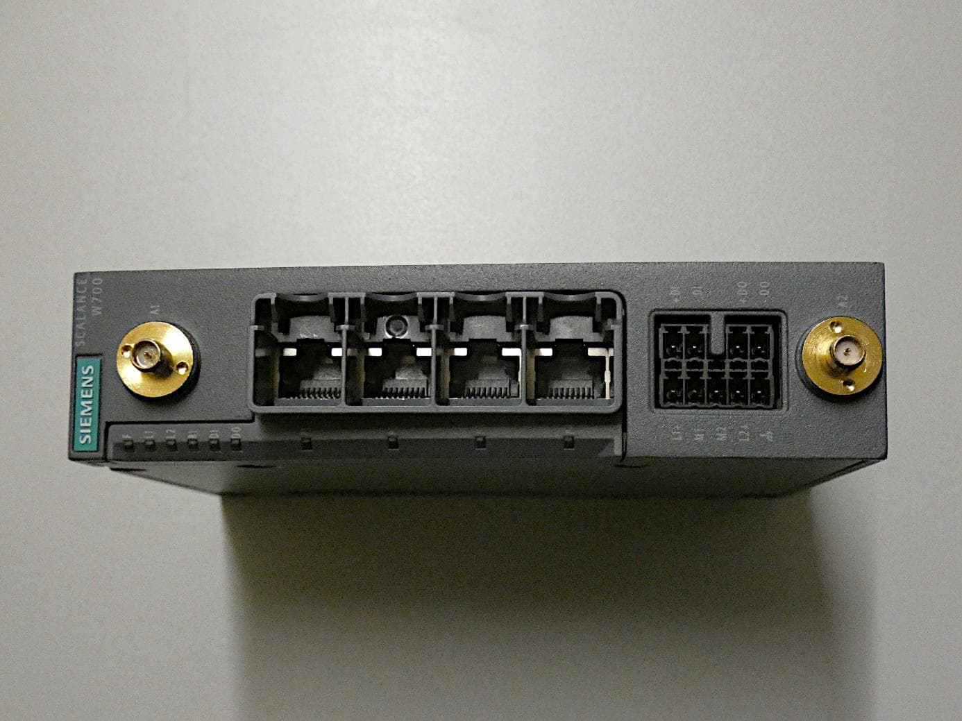
LYHMSAXV1
Apr 13, 2023MSAX-W1-RJ-E2 / MSAX-W1-RJ-E2-NO
Equipment Class
JBP - Part 15 Class B Computing Device Peripheral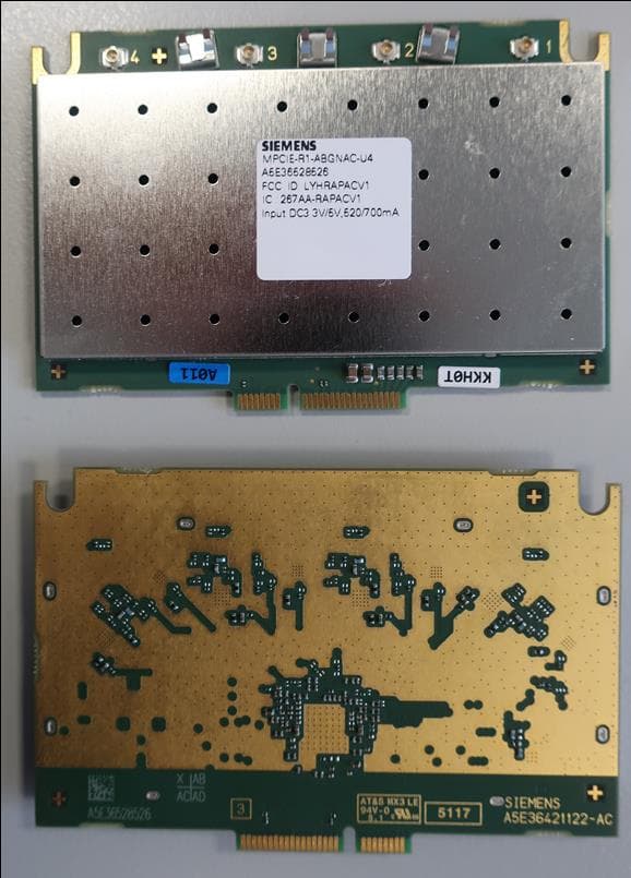
LYHRAPACV1
Feb 20, 2020Industrial Wireless LAN Access Point Module
Equipment Class
NII - Unlicensed National Information Infrastructure TX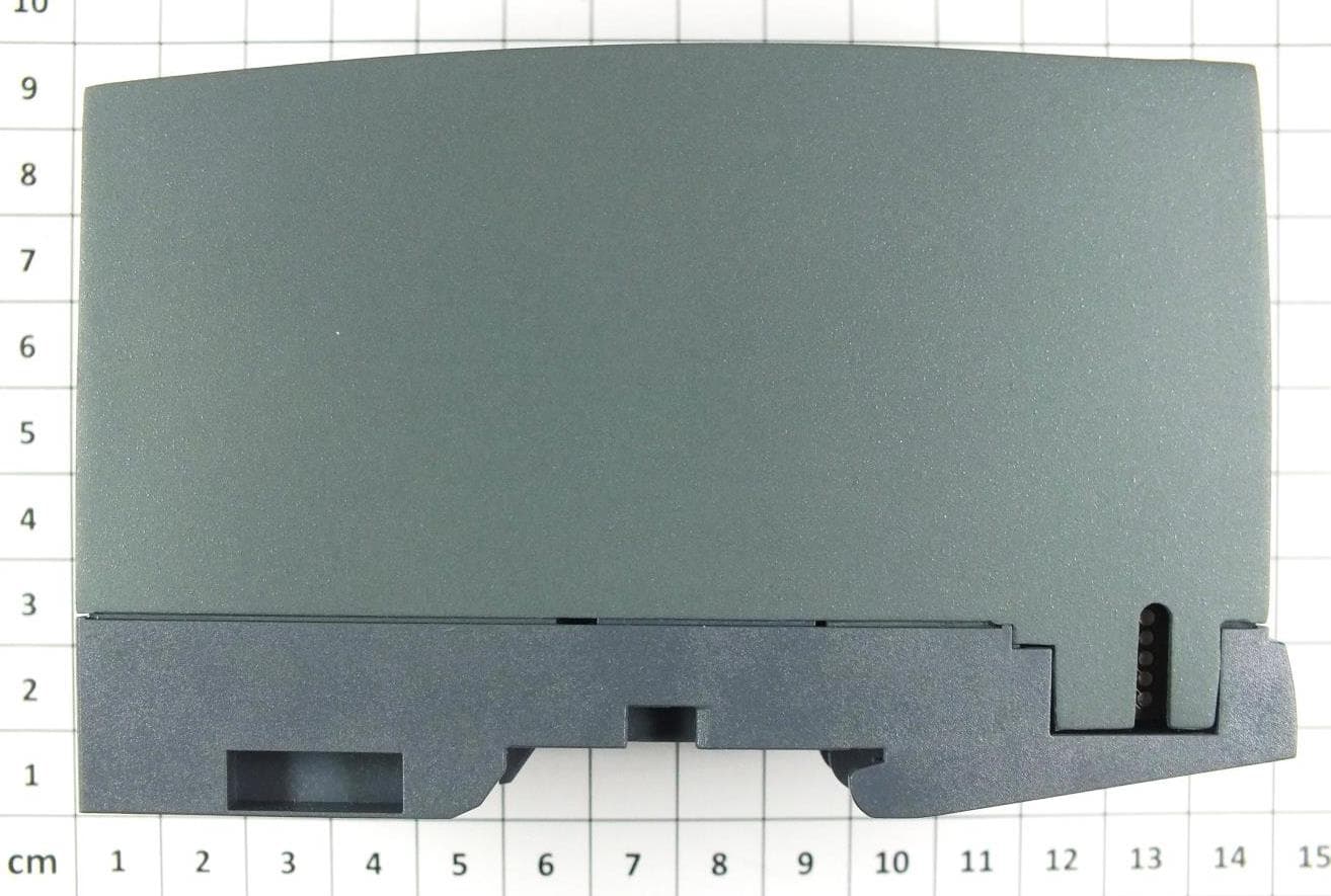
LYHELN1V1
Mar 31, 2014Industrial WLAN Access Point
Equipment Class
NII - Unlicensed National Information Infrastructure TX