LYHW700-2-V12.4/5 GHz IEEE 802.11a/b/g WLAN Access Point
Siemens AG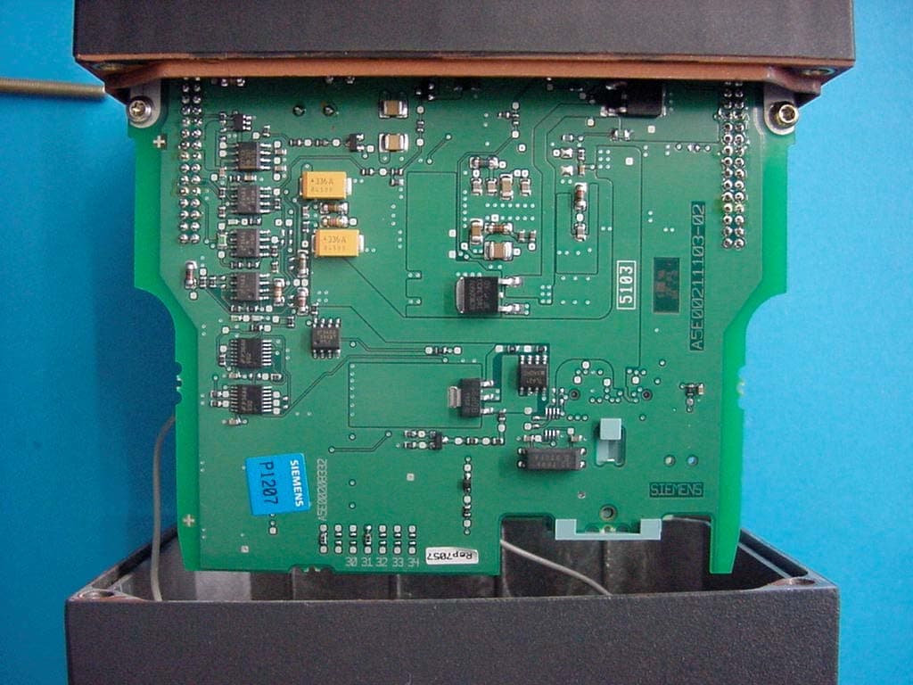
Click to zoom
Application Details
- Equipment Class
- NII - Unlicensed National Information Infrastructure TX
- Date of Grant
- Jun 22, 2004
- Application Purpose
- Original Equipment
- Date of Application
- Jun 22, 2004
- Equipment Note
- 2.4/5 GHz IEEE 802.11a/b/g WLAN Access Point
- Frequency Range
- 5725.00000000 - 5825.00000000
- Company
- Siemens AG
- Country
- Germany
Documents & Files
Document Text
Text extracted from the exhibit documents filed with the FCC. Open a document above to read the original.
Users Manual
SIMATIC NET Preface, Contents Basic Information on Wireless LAN Communication 1 Description of the SCALANCE W 700 2 Commissioning 3 Configuration with the Primary Setup Tool 4 Configuration Using the Wizards of Web Based Management 5 Configuration Using Web Based Management and the Command Line Interface 6 Technical Specifications 7 Glossary, Index, Certificates and Approvals, Support Operating Instructions SCALANCE W 744-1pro (Client Module) SCALANCE W 788-1pro (Access Point) SCALANCE W 788-2pro (Dual Access Point) C79000-G8976-C184-01 Release 02/2004 © Copyright Siemens AG, 1998 to 2004 - All rights reserved The reproduction, transmission or use of this document or its contents is not permitted without express written authority. Offenders will be liable for damages. All rights, including rights created by patent grant or registration of a utility model or design, are reserved. Disclaimer We have checked the contents of this manual for agreement with the hardware and software described. Since deviations cannot be precluded entirely, we cannot guarantee full agreement. However, the data in this manual are reviewed regularly and any necessar Classification of Safety-Related Notices This document contains notices which you should observe to ensure your own per- sonal safety, as well as to protect the product and connected equipment. These no- tices are highlighted in the manual by a warning triangle and are marked as follows according to the level of danger: ! Danger indicates that death or severe personal injury will result if proper precautions are not taken. ! Warning indicates that death or severe personal injury can result if proper precautions are not taken. ! Caution with a warning triangle indicates that minor personal injury can result if proper precau- tions are not taken. Caution without a warning triangle indicates that damage to property can result if proper pre- cautions are not taken. Notice indicates that an undesirable result or status can occur if the relevant notice is ig- nored. Note highlights important information on the product, using the product, or part of the docu- mentation that is of particular importance and that will be of benefit to the user. y corrections included in subsequent editions. Suggestions fo r improvement are welcomed. Siemens AG Automation and Drives Industrial Communication Postfach 4848, D-90327 Nürnberg C79000-G8976-C184-01 Technical data subject to change. Siemens Aktiengesellschaft Printed in the Federal Republic of Germany 2 Operating Instructions SCALANCE W 788-1pro / SCALANCE W 788-2pro C79000-G8976-C184-01 3 Trademarks SIMATIC , SIMATIC NET , SINEC and SIMATIC NET Networking for Industry ® are registered trademarks of Siemens AG. Third parties using for their own purposes any other names in this document which re- fer to trademarks might infringe upon the rights of the trademark owners. Safety Instructions Regarding your Product Before you use the product described here, read the safety instructions below thor- oughly. Qualified Personnel Only qualified personnel should be allowed to install and work on this equipment. Qualified persons are defined as persons who are authorized to commission, to ground, and to tag circuits, equipment, and systems in accordance with established safety practices and standards. Correct Usage of Hardware Products Please note the following regarding the correct usage of hardware products: Caution This device may only be used for the applications described in the catalog or the tech- nical description, and only in connection with devices or components from other manufacturers which have been approved or recommended by Siemens. This product can only function correctly and safely if it is transported, stored, set up, and installed correctly, and operated and maintained as recommended. Before you use the supplied sample programs or programs you have written yourself, make certain that no injury to persons nor damage to equipment can result in your plant or process. EU Directive: Do not start up until you have established that the machine on which you intend to run this component complies with the directive 89/392/EEC. Operating Instructions SCALANCE W 788-1pro / SCALANCE W 788-2pro 4 C79000-G8976-C184-01 Correct Usage of Software Products Please note the following regarding the correct usage of software products: Caution This software may only be used for the applications described in the catalog or the technical description, and only in connection with software products, devices, or com- ponents from other manufacturers which have been approved or recommended by Siemens. Before you use the supplied sample programs or programs you have written yourself, make certain that no injury to persons nor damage to equipment can result in your plant or process. Prior to Startup Before putting the product into operation, note the following warning: Caution Prior to startup you must observe the instructions in the relevant documentation. For ordering data of the documentation please refer to the catalogs or contact your local SIEMENS representative. Preface Purpose of the Manual This manual is intended to provide you with the information you require to install, commission and operate the SCALANCE W 788 correctly. It explains how to con- figure the SCALANCE W 788 and how to integrate the SCALANCE W 788 in a WLAN network. Scope of this Manual This manual describes the products SCALANCE W 744-1pro, SCALANCE W 788- 1pro and SCALANCE W 788-2pro. Where the description applies to all products, the name SCALANCE W 700 is used. Where the description applies to a specific product, the full name of the product is used. This manual applies to the following software versions: ● SCALANCE W 700 firmware as of Version 1.0 ● Primary Setup Tool as of Version 2.0.10 Operating Instructions SCALANCE W 788-1pro / SCALANCE W 788-2pro C79000-G8976-C184-01 5 Preface Orientation in the Documentation Apart from the operating instructions you are…
Text truncated - open the document above for the full version.
External Photos
SRD-Testreport CETECOM ICT Services GmbH Saarbruecken, Germany Test report No.: 5-4456-01-04l/04Date: 2004-06-08Page 116 of 132 Test sample: SRD-Testreport CETECOM ICT Services GmbH Saarbruecken, Germany Test report No.: 5-4456-01-04l/04Date: 2004-06-08Page 117 of 132 SRD-Testreport CETECOM ICT Services GmbH Saarbruecken, Germany Test report No.: 5-4456-01-04l/04Date: 2004-06-08Page 118 of 132 SRD-Testreport CETECOM ICT Services GmbH Saarbruecken, Germany Test report No.: 5-4456-01-04l/04Date: 2004-06-08Page 119 of 132 SRD-Testreport CETECOM ICT Services GmbH Saarbruecken, Germany Test report No.: 5-4456-01-04l/04Date: 2004-06-08Page 120 of 132
Internal Photos
SRD-Testreport CETECOM ICT Services GmbH Saarbruecken, Germany Test report No.: 5-4456-01-04l/04Date: 2004-06-08Page 120 of 132 SRD-Testreport CETECOM ICT Services GmbH Saarbruecken, Germany Test report No.: 5-4456-01-04l/04Date: 2004-06-08Page 121 of 132 SRD-Testreport CETECOM ICT Services GmbH Saarbruecken, Germany Test report No.: 5-4456-01-04l/04Date: 2004-06-08Page 122 of 132 SRD-Testreport CETECOM ICT Services GmbH Saarbruecken, Germany Test report No.: 5-4456-01-04l/04Date: 2004-06-08Page 123 of 132 SRD-Testreport CETECOM ICT Services GmbH Saarbruecken, Germany Test report No.: 5-4456-01-04l/04Date: 2004-06-08Page 124 of 132 SRD-Testreport CETECOM ICT Services GmbH Saarbruecken, Germany Test report No.: 5-4456-01-04l/04Date: 2004-06-08Page 125 of 132
RF Exposure Info
SRD-Testreport CETECOM ICT Services GmbH Saarbruecken, Germany Test report No.: 5-4456-01-04l/04Date: 2004-06-08Page 90 of 132 3.21 MPE RF EXPOSURE INFO Environmental evaluation measurements of Maximum Permissible Exposure (MPE) to radio frequency (RF) radiation from transmitting devices for compliance with the technical rules and regulations of the U.S. Federal Communications Commission and Industry Canada. Description of EUT Siemens AG Model: SCALANCE 788-2PRO, (FCC ID: FCC ID:LYHW700-1-V1 / LYHW700-2-V1 and IC:267AA-W700V1) with flat patch point to point Antenna from Wistec. 1) The probe was positioned on a table at a separation distance of 20 cm from the radiating antenna and at a starting height of 5 cm to the center of the probe. 2) The table was positioned so that the initial start angle was 0 degrees. 3) The EUT was powered on and allowed sufficient time to stabilize. The EUT was operated at full power on a desired frequency. 4) The analyzer and the field probe was set for maximum hold, and set on the appropriate power range. 5) The table was rotated 360 degrees and the maximum reading was obtained for that elevation. 6) The antennas were lifted and lowered at maximum value in the horizontal plane to find the maximum in vertical position. Result: The max measured MPE value on a distance of 20 cm is: 0.33 mW/cm 2 by measurement with the analyzer 0.35 mW/cm 2 by measurement with the field probe MPE System Specification: -Electromagnetic Radiation Field probe, PMM Model 8053 Frequency Range: 1 MHz to 40 GHz Calibration date: 05/2005 - Signal analyzer FSIQ26 from R&S Frequency range: 10 Hz to 26.5 GHz Calibration date: 07/2003 Limit: 1mW/ cm 2 is the reference level for general public exposure according to the OET Bulletin 65, Edition 97-01 Table 1. SRD-Testreport CETECOM ICT Services GmbH Saarbruecken, Germany Test report No.: 5-4456-01-04l/04Date: 2004-06-08Page 38 of 132 3.10 MPE calculation These equations are generally accurate in the far field of an antenna but will over predict power density in the near field, where they could be used for making a “worst case” prediction. S = PG/4πR 2 whereS = power density ( in appropriate units, e.g. mW/cm 2 ) P = power input to the antenna (in appropriate units e.g. mW) G = power gain of the antenna in the direction of interest relative to the isotropic radiator R = distance to the center of radiation of the antenna (appropriate units e.g. cm) Or S = EIRP/4πR 2 where EIRP = equivalent isotropically radiated power Calculation: (Antenna 1)Calculation: (Antenna 2) (Calculated for max. EIRP) EIRP: 27.3 dBm = 537.0 mWEIRP: 25.1 dBm = 323.6 mW calculated at distance of 20 cm: power density = 537.0 /4π20 2 = 0.107 mW/ cm 2 power density = 323.6/4π20 2 = 0.064 mW/ cm 2 Limit: 1mW/ cm 2 is the reference level for general public exposure according to the OET Bulletin 65, Edition 97-01 Table 1.
Test Report
G:\2_RSC\PROJEKTE\04\5er Projekte\5-4456-01-04_04 Siemens Karlsruhe IWLAN Robust AP\Ergebnisse\5 GHz\5-4456-1-4d.doc Recognized by the Federal Communications Commission Anechoic chamber registration no.: 90462 (FCC) Anechoic chamber registration no.: 3463 (IC) TCB ID: DE 0001 Accredited by the German Accreditation Council DAR–Registration Number TTI–P–G 081/94-D0 Independent ETSI compliance test house ETSI Accredited Bluetooth™ Test Facility (BQTF) Test report no.: 5-4456-01-04l/04 FCC Part 15.407 / CANADA RSS-210 FCC ID:LYHW700-2-V1 IC:267AA-W700-V1 SCALANCE W788-2PRO CETECOM – ICT Services GmbH Untertürkheimerstr. 6-10 D-66117 Saarbrücken, Germany Telephone: + 49 (0) 681 / 598-0 Fax: + 49 (0) 681 / 598-9075 BLUETOOTH is a trademark owned by Bluetooth SIG, Inc. and licensed to Cetecom SRD-Testreport CETECOM ICT Services GmbH Saarbruecken, Germany Test report No.: 5-4456-01-04l/04Date: 2004-06-08Page 2 of 132 Table of contents 1. ADMINISTRATIVE DATA ....................................................................................................................................... 3 1.1.A DMINISTRATIVE DATA OF THE TEST FACILITY..................................................................................................... 3 1.1.1Identification of the testing laboratory ......................................................................................................... 3 1.1.2Organizational items .................................................................................................................................... 3 1.1.3Applicant ́s details ........................................................................................................................................ 4 1.2A DMINISTRATIVE DATA OF MANUFACTURER / MEMBER........................................................................................ 4 1.3D ESCRIPTION OF THE EQUIPMENT UNDER TEST (EUT) .......................................................................................... 5 1.3.1EUT: Type, S/N etc. ...................................................................................................................................... 5 1.3.2If RF component testing only, description of additional used HW/SW .........................................................5 1.3.3A DDITIONAL EUT INFORMATION...................................................................................................................... 5 1.3.4EUT operating modes ................................................................................................................................... 6 1.3.5Extreme conditions testing values................................................................................................................. 6 2. TEST STANDARD & SUMMARY LIST OF ALL PERFORMED TEST CASES .............................................. 7 3. RF MEASUREMENT TESTING ............................................................................................................................. 8 3.1D ESCRIPTION OF TEST SET-UP................................................................................................................................8 3.1.1Radiated measurements ................................................................................................................................ 8 3.1.2Conducted measurements ............................................................................................................................. 8 3.1.3AC-conducted measurements........................................................................................................................ 8 3.2R EFERENCED DOCUMENTS.................................................................................................................................... 9 3.3 A DDITIONAL COMMENTS....................................................................................................................................... 9 3.4A NTENNA GAIN..................................................................................................................................................... 9 3.5 P EAK TRANSMIT POWER §15.407A(3)+(4) ................................................................................................... 10 3.6S PECTRAL DENSITY CONDUCTED §15.407(A5) ............................................................................................... 19 3.7R ATIO OF PEAK EXCURSION §15.407(A6) ....................................................................................................... 23 3.8U NDESIRABLE EMISSION LIMITS AT BAND EDGES 15.407 (B3).......................................................................... 27 3.9S PURIOUS (CONDUCTED) 15.407 (B3)........................................................................................................... 29 3.10 MPE CALCULATION.............................................................................................................................................. 38 3.11M AX. PEAK OUTPUT POWER (RADIATED) §15.247 (B) (1) ................................................................................... 39 3.12 S PURIOUS EMISSIONS - RADIATED (TRANSMITTER) §15.209 ................................................................................. 41 3.13 S PURIOUS EMISSIONS RADIATED (RX) 15.209 .................................................................................................. 56 3.14 S PURIOUS EMISSIONS - RADIATED <30 MHZ (VALID FOR ALL ANTENNA TYPES) §15.109...................................... 60 3.15C ONDUCTED EMISSIONS <30 MHZ §15.107/207.............................................................................................. 61 3.16 P EAK TRANSMIT POWER §15.407A(3)+(4) ............................................................................................... 62 3.17S PECTRAL DENSITY CONDUCTED §15.407(A5) .....................................................................................…
Text truncated - open the document above for the full version.
Test Setup Photos
SRD-Testreport CETECOM ICT Services GmbH Saarbruecken, Germany Test report No.: 5-4456-01-04l/04Date: 2004-06-08Page 111 of 132 4 Photographs Test site: Antenna 1 SRD-Testreport CETECOM ICT Services GmbH Saarbruecken, Germany Test report No.: 5-4456-01-04l/04Date: 2004-06-08Page 112 of 132 Test site: Antenna 1 SRD-Testreport CETECOM ICT Services GmbH Saarbruecken, Germany Test report No.: 5-4456-01-04l/04Date: 2004-06-08Page 113 of 132 Test site: Antenna 2 SRD-Testreport CETECOM ICT Services GmbH Saarbruecken, Germany Test report No.: 5-4456-01-04l/04Date: 2004-06-08Page 114 of 132 Test site: Antenna 3 SRD-Testreport CETECOM ICT Services GmbH Saarbruecken, Germany Test report No.: 5-4456-01-04l/04Date: 2004-06-08Page 115 of 132 AC-conducted:
Contact Information
Applicant
Malgorzata Janson(Dr.)
Test Firm
Cetecom ICT Services GmbHRalf Hoehn
Technical Specifications
| # | Rule Parts | Frequency Range | Power Output |
|---|---|---|---|
| 2 | 15E | 5.72 GHz - 5.83 GHz | 250.00 mW |
Other Applications from Siemens AG
LYHMRM85633M
Aug 04, 2026SCALANCE MRM85633M
Equipment Class
CBD - Citizens Band Category A and B Devices
LYH-MS200
May 10, 2023Vibration and temperature sensor
Equipment Class
DTS - Digital Transmission System
LYHMSAXV1
Apr 13, 2023MSAX-W1-RJ-E2 / MSAX-W1-RJ-E2-NO
Equipment Class
JBP - Part 15 Class B Computing Device Peripheral
LYHRAPACV1
Feb 20, 2020Industrial Wireless LAN Access Point Module
Equipment Class
NII - Unlicensed National Information Infrastructure TX
LYHELN1V1
Mar 31, 2014Industrial WLAN Access Point
Equipment Class
NII - Unlicensed National Information Infrastructure TX