M5LBL09TXBaseline Speed Transmitter
ZEITBIKE LLC
Click to zoom
Application Details
- Equipment Class
- DCD - Part 15 Low Power Transmitter Below 1705 kHz
- Date of Grant
- Oct 07, 2012
- Application Purpose
- Original Equipment
- Date of Application
- Oct 07, 2012
- Equipment Note
- Baseline Speed Transmitter
- Frequency Range
- 0.11200000 - 0.11200000
- Company
- ZEITBIKE LLC
- Country
- United States
Documents & Files
Document Text
Text extracted from the exhibit documents filed with the FCC. Open a document above to read the original.
Users Manual
1 Bike Computer WireLeSS Deutsch English Français Italiano Español Nederlands Dansk Suomi Svensk Norsk Türkçe Slovenščina Slovenčina Português Polski Magyar Česky Български Русский Română WATERTIGHT TOOL FREE WIRELESS BASELINE WIRELESS Manual.indd 119.09.12 15:01 2 BIKE COMPUTER WIRELESS Inhalt Content Contenu Contenido Contenudo Inhoud Innehåll Indhold Sisältö Innhold İçerik Vsebina Obsah Conteúdo Tresc Tartalom Zawartość Съдържание Содержание Cuprins DE FR IT ES NL SE DK FI TR SK NO SL PT PL HU CZ BG RU RO GB BASELINE WIRELESS Manual.indd 219.09.12 15:01 3 1 ? oder or ou 4456332 BASELINE WIRELESS Manual.indd 319.09.12 15:01 4 2 90° 4 x 4 x A BCD BASELINE WIRELESS Manual.indd 419.09.12 15:01 5 34 + BASELINE WIRELESS Manual.indd 519.09.12 15:01 6 56 7 BASELINE WIRELESS Manual.indd 619.09.12 15:01 7 7 CLICK ! BASELINE WIRELESS Manual.indd 719.09.12 15:01 8 8 + BASELINE WIRELESS Manual.indd 819.09.12 15:01 9 9 BASELINE WIRELESS Manual.indd 919.09.12 15:01 10 10 Max. 30° Max. 70 cm BASELINE WIRELESS Manual.indd 1019.09.12 15:01 11 11 Max. 5 mm BASELINE WIRELESS Manual.indd 1119.09.12 15:01 12 DE FR IT NL SE DK FI NO TR SL SK PT ES GB Achtung: WIRELESS muss durch Tastendruck des Computers aktiviert werden! Attention: le WIRELESS doit être activé en appuyant sur le bouton de la tête du compteur. Attenzione: WIRELESS deve essere attivato premendo un tasto del computer. Opgelet: WIRELESS moet door de drukknop op de computer geactiveerd worden! Obs: WIRELESS måste aktiveras genom att trycka på någon av knapparna på datorn. Bemærk: WIRELESS skal aktiveres ved at trykke på en knap på computerhovedet. Huomio: WIRELESS kytketään toimintaan painamalla näppäintä mittarin päältä. Obs! WIRELESS må aktiveres ved tastetrykk på datamaskinen! Dikkat: WIRELESS cihaz Łzerindeki bir butona basűlarak baļlatűlmalűdűr. Pozor: WIRELESS mora biti aktiviran s pritiskom na gumb števca. Pozor: WIRELESS sa musí aktivovať stlačením tlačidla komputra! Atenção: o WIRELESS activa-se pressionando um butão situado no computador. Atención: El WIRELESS se activa pulsando un boton situado en el computador. Attention: WIRELESS must be activated by pressing a button on computer head. PL HU CZ BG Uwaga! WIRELESS musi być aktywowany przyciskiem w komputerze rowerowym! Figyelmeztetés: Az WIRELESS-t a computeren lévő gombbal lehet elindítani. Pozor: WIRELESS musí být aktivováno zmáknutím jednoho z tlačítek Vašeho cyklocomputeru. WIRELESS трябва да бъде активиран чрез натискане на бутона в горната част на компютъра. WIRELESS приводится в действие нажатием на кнопку в верхней части компьютера. RU BASELINE WIRELESS Manual.indd 1219.09.12 15:01 13 DE NO FR IT NL SE DK FI TR ES GB Nach jedem Vorbeiführen des Magneten blinkt die Kontroll-LED des Senders. Etter hver forbiføring av magneten blinker kontroll-LEDen til senderen. Attention: le WIRELESS doit être activé en appuyant sur le bouton de la tête du compteur. Pendant 2 minutes, la LED doit clignoter à chaque passage de l'aimant. Per i prossimi 2 minuti i LED lampeggeranno ad ogni passaggio del magnete. De eerstvolgende 2 minuten knippert het controle lampje bij het voorbijkomen van de spaakmagneet. Varje gång magneten passerar så blinkar kontrollampan (2 minuter). I de næste 2 minutter, skal dioderne blinke ved hver magnetpassage. Seuraavat 2 minuuttia, LED-valon tulisi välkkyä aina magneetin kohdalla. 2 dakika süresince LED ́ler mıknatısın her geçișinde yanması gerekir. Durante los dos minutos siguientes, los LED lucirán intermitentemente a cada paso del imán. For the next 2 minutes, the LED should blink with each pass of the magnet. Pozor: WIRELESS musí být aktivováno zmáknutím jednoho z tlačítek Vašeho cyklocomputeru. WIRELESS трябва да бъде активиран чрез натискане на бутона в горната част на компютъра. WIRELESS приводится в действие нажатием на кнопку в верхней части компьютера. SL SK PT V naslednjih 2 min LED dioda utripa ob teku magneta mimo senzorja. Po každom prejdení magnetu zabliká LED kontrolka vysielača. Durante os 2 minutos seguintes,os LED acenderão interminentemente a cada passo do iman. PL HU CZ BG Aby ponownie przeprowadzić test baterii, po 2 min. aktywować system przyciskiem w komputerze. A következő 2 percben a LED-eknek villogniuk kell a mágnes mindkét polusa felé. Obě ledki by měli svítit asi 2 minuty součastně s každým protočením magnetu. Эа следващите 2 минути диодът ще мига при всяко преминаване на магнита. B течение следующих двух минут индикаторы должны мигать при каждом прохождении магнита. RU BASELINE WIRELESS Manual.indd 1319.09.12 15:01 14 Batterie Typ CR 2032 Batteri: litium knappcelle CR 2032 Batérie: lítiovy okrúhly monočlánok CR 2032 Pile type CR 2032 Batteria litio CR 2032 Batterij type CR 2032 Batteri typ CR 2032 Batteri type CR 2032 Patteri tyyppi CR 2032 Pil tipi: CR 2032 Baterija: litijeva gumbasta baterija CR 2032 Pilha tipo CR 2032 Pila tipo CR 2032 Battery type CR 2032 Bateria płaska litowa CR 2032 Elem típusa: CR 2032 Typ baterie CR 2032 Батерия: литиева батерия тип копче CR 2032 Батарея: литийная кнопочная батарея CR 2032 DE NO FR IT NL SE DK FI TR ES GB SL SK PT PL HU CZ BG RU BASELINE WIRELESS Manual.indd 1419.09.12 15:01 15 • Sicherungshülse über Magnet geschoben (Bild 7)? • Computer richtig auf der Halterung eingerastet? • WIRELESS durch Computertastendruck aktiviert? • Kontakte auf Oxidation/Korrosion überprüft? • Abstand zw. Magnet und Sensor überprüft? (max. 5 mm) • Magnet richtig positioniert? • Überprüft ob Magnet magnetisiert ist? • Batterie überprüfen. • Batterie richtig eingelegt. (Plus und Minus beachten) • Batteriekontakt OK? (vorsichtig nachbiegen!) • Safety shell is pushed over the magnet (fig. 7)? • Is the computer properly placed in the bracket? • Is WIRELESS activated by pressing computer button? • Did you check the contacts for oxidation/corrosion? • Did you check the distance? (max. 5 mm / 0,20 inch) • Is the magnet positioned in the right way? • Is the magnet magnetizised? • Check the battery. • Did you put the battery …
Text truncated - open the document above for the full version.
Users Manual
1 Bike Computer WireLeSS Deutsch English Français Italiano Español Nederlands Dansk Suomi Svensk Norsk Türkçe Slovenščina Slovenčina Português Polski Magyar Česky Български Русский Română WATERTIGHT TOOL FREE WIRELESS BASELINE WIRELESS Manual.indd 119.09.12 15:01 2 BIKE COMPUTER WIRELESS Inhalt Content Contenu Contenido Contenudo Inhoud Innehåll Indhold Sisältö Innhold İçerik Vsebina Obsah Conteúdo Tresc Tartalom Zawartość Съдържание Содержание Cuprins DE FR IT ES NL SE DK FI TR SK NO SL PT PL HU CZ BG RU RO GB BASELINE WIRELESS Manual.indd 219.09.12 15:01 3 1 ? oder or ou 4456332 BASELINE WIRELESS Manual.indd 319.09.12 15:01 4 2 90° 4 x 4 x A BCD BASELINE WIRELESS Manual.indd 419.09.12 15:01 5 34 + BASELINE WIRELESS Manual.indd 519.09.12 15:01 6 56 7 BASELINE WIRELESS Manual.indd 619.09.12 15:01 7 7 CLICK ! BASELINE WIRELESS Manual.indd 719.09.12 15:01 8 8 + BASELINE WIRELESS Manual.indd 819.09.12 15:01 9 9 BASELINE WIRELESS Manual.indd 919.09.12 15:01 10 10 Max. 30° Max. 70 cm BASELINE WIRELESS Manual.indd 1019.09.12 15:01 11 11 Max. 5 mm BASELINE WIRELESS Manual.indd 1119.09.12 15:01 12 DE FR IT NL SE DK FI NO TR SL SK PT ES GB Achtung: WIRELESS muss durch Tastendruck des Computers aktiviert werden! Attention: le WIRELESS doit être activé en appuyant sur le bouton de la tête du compteur. Attenzione: WIRELESS deve essere attivato premendo un tasto del computer. Opgelet: WIRELESS moet door de drukknop op de computer geactiveerd worden! Obs: WIRELESS måste aktiveras genom att trycka på någon av knapparna på datorn. Bemærk: WIRELESS skal aktiveres ved at trykke på en knap på computerhovedet. Huomio: WIRELESS kytketään toimintaan painamalla näppäintä mittarin päältä. Obs! WIRELESS må aktiveres ved tastetrykk på datamaskinen! Dikkat: WIRELESS cihaz Łzerindeki bir butona basűlarak baļlatűlmalűdűr. Pozor: WIRELESS mora biti aktiviran s pritiskom na gumb števca. Pozor: WIRELESS sa musí aktivovať stlačením tlačidla komputra! Atenção: o WIRELESS activa-se pressionando um butão situado no computador. Atención: El WIRELESS se activa pulsando un boton situado en el computador. Attention: WIRELESS must be activated by pressing a button on computer head. PL HU CZ BG Uwaga! WIRELESS musi być aktywowany przyciskiem w komputerze rowerowym! Figyelmeztetés: Az WIRELESS-t a computeren lévő gombbal lehet elindítani. Pozor: WIRELESS musí být aktivováno zmáknutím jednoho z tlačítek Vašeho cyklocomputeru. WIRELESS трябва да бъде активиран чрез натискане на бутона в горната част на компютъра. WIRELESS приводится в действие нажатием на кнопку в верхней части компьютера. RU BASELINE WIRELESS Manual.indd 1219.09.12 15:01 13 DE NO FR IT NL SE DK FI TR ES GB Nach jedem Vorbeiführen des Magneten blinkt die Kontroll-LED des Senders. Etter hver forbiføring av magneten blinker kontroll-LEDen til senderen. Attention: le WIRELESS doit être activé en appuyant sur le bouton de la tête du compteur. Pendant 2 minutes, la LED doit clignoter à chaque passage de l'aimant. Per i prossimi 2 minuti i LED lampeggeranno ad ogni passaggio del magnete. De eerstvolgende 2 minuten knippert het controle lampje bij het voorbijkomen van de spaakmagneet. Varje gång magneten passerar så blinkar kontrollampan (2 minuter). I de næste 2 minutter, skal dioderne blinke ved hver magnetpassage. Seuraavat 2 minuuttia, LED-valon tulisi välkkyä aina magneetin kohdalla. 2 dakika süresince LED ́ler mıknatısın her geçișinde yanması gerekir. Durante los dos minutos siguientes, los LED lucirán intermitentemente a cada paso del imán. For the next 2 minutes, the LED should blink with each pass of the magnet. Pozor: WIRELESS musí být aktivováno zmáknutím jednoho z tlačítek Vašeho cyklocomputeru. WIRELESS трябва да бъде активиран чрез натискане на бутона в горната част на компютъра. WIRELESS приводится в действие нажатием на кнопку в верхней части компьютера. SL SK PT V naslednjih 2 min LED dioda utripa ob teku magneta mimo senzorja. Po každom prejdení magnetu zabliká LED kontrolka vysielača. Durante os 2 minutos seguintes,os LED acenderão interminentemente a cada passo do iman. PL HU CZ BG Aby ponownie przeprowadzić test baterii, po 2 min. aktywować system przyciskiem w komputerze. A következő 2 percben a LED-eknek villogniuk kell a mágnes mindkét polusa felé. Obě ledki by měli svítit asi 2 minuty součastně s každým protočením magnetu. Эа следващите 2 минути диодът ще мига при всяко преминаване на магнита. B течение следующих двух минут индикаторы должны мигать при каждом прохождении магнита. RU BASELINE WIRELESS Manual.indd 1319.09.12 15:01 14 Batterie Typ CR 2032 Batteri: litium knappcelle CR 2032 Batérie: lítiovy okrúhly monočlánok CR 2032 Pile type CR 2032 Batteria litio CR 2032 Batterij type CR 2032 Batteri typ CR 2032 Batteri type CR 2032 Patteri tyyppi CR 2032 Pil tipi: CR 2032 Baterija: litijeva gumbasta baterija CR 2032 Pilha tipo CR 2032 Pila tipo CR 2032 Battery type CR 2032 Bateria płaska litowa CR 2032 Elem típusa: CR 2032 Typ baterie CR 2032 Батерия: литиева батерия тип копче CR 2032 Батарея: литийная кнопочная батарея CR 2032 DE NO FR IT NL SE DK FI TR ES GB SL SK PT PL HU CZ BG RU BASELINE WIRELESS Manual.indd 1419.09.12 15:01 15 • Sicherungshülse über Magnet geschoben (Bild 7)? • Computer richtig auf der Halterung eingerastet? • WIRELESS durch Computertastendruck aktiviert? • Kontakte auf Oxidation/Korrosion überprüft? • Abstand zw. Magnet und Sensor überprüft? (max. 5 mm) • Magnet richtig positioniert? • Überprüft ob Magnet magnetisiert ist? • Batterie überprüfen. • Batterie richtig eingelegt. (Plus und Minus beachten) • Batteriekontakt OK? (vorsichtig nachbiegen!) • Safety shell is pushed over the magnet (fig. 7)? • Is the computer properly placed in the bracket? • Is WIRELESS activated by pressing computer button? • Did you check the contacts for oxidation/corrosion? • Did you check the distance? (max. 5 mm / 0,20 inch) • Is the magnet positioned in the right way? • Is the magnet magnetizised? • Check the battery. • Did you put the battery …
Text truncated - open the document above for the full version.
External Photos
Page 1 of 1 TÜV SÜD Hong Kong Ltd. 3/F, West Wing, Phase 2, 10 Science Park West Avenue, Shatin, Hong Kong. Appendix B Date: 2011-12-09 Test report no.: 60.870.11.022.01F Model no.: TX Photos of EUT – External EUT Photos Page 2 of 2 TÜV SÜD Hong Kong Ltd. 3/F, West Wing, Phase 2, 10 Science Park West Avenue, Shatin, Hong Kong. Test report no.: 60.870.11.022.01F Model no.: TX
External Photos
Page 1 of 1 TÜV SÜD Hong Kong Ltd. 3/F, West Wing, Phase 2, 10 Science Park West Avenue, Shatin, Hong Kong. Appendix B Date: 2011-12-09 Test report no.: 60.870.11.022.01F Model no.: TX Photos of EUT – External EUT Photos Page 2 of 2 TÜV SÜD Hong Kong Ltd. 3/F, West Wing, Phase 2, 10 Science Park West Avenue, Shatin, Hong Kong. Test report no.: 60.870.11.022.01F Model no.: TX
ID Label/Location Info
FCC ID & Location
ID Label/Location Info
FCC ID & Location
Internal Photos
Page 1 of 1 TÜV SÜD Hong Kong Ltd. 3/F, West Wing, Phase 2, 10 Science Park West Avenue, Shatin, Hong Kong. Appendix C Date: 2011-12-09 Test report no.: 60.870.11.022.01F Model no.: TX Photos of EUT – Internal EUT Photos
Internal Photos
Page 1 of 1 TÜV SÜD Hong Kong Ltd. 3/F, West Wing, Phase 2, 10 Science Park West Avenue, Shatin, Hong Kong. Appendix C Date: 2011-12-09 Test report no.: 60.870.11.022.01F Model no.: TX Photos of EUT – Internal EUT Photos
Test Report
Report No.: 60.870.11.022.01F Date: 2011-12-09 Page 1 of 16 TÜV SÜD Hong Kong Ltd. 3/F, West Wing, Phase 2, 10 Science Park West Avenue, Shatin, Hong Kong. TEST REPORT Applicant: SIGMA Elektro GmbH.. Dr. Julius Leber Str.15, Neustadt 67433, Germany Description of Samples:Model name: Baseline Speed Transmitter Brand name: SIGMA Model no.:TX FCCID:M5LBL09TX Date Samples Received:2011-11-15 Date Tested:2011-11-15 to 2011-12-04 Investigation Requested:FCC Part 15, Section 15.209 Conclusions:The submitted product COMPLIED with the requirements of Federal Communications Commission [FCC] Rules and Regulations Part 15. The tests were performed in accordance with the standards described above and on Section 2.2 in this Test Report. Remarks:---- Checked by:Approved by:- Nicolas ChengJeff Pong Project ManagerOperation Manager Wireless & Telecom departmentWireless & Telecom department Report No.: 60.870.11.022.01F Date: 2011-12-09 Page 2 of 16 TÜV SÜD Hong Kong Ltd. 3/F, West Wing, Phase 2, 10 Science Park West Avenue, Shatin, Hong Kong. CONTENT: Cover Page 1 of 16 Content Page 2 of 16 1.0General Details 1.1Test Laboratory Page 4 of 16 1.2Applicant Details Page 4 of 16 1.3Equipment Under Test [EUT] Page 5 of 16 1.4 Equipment Modification Page 5 of 16 1.5 Related Submittal(s) Grants Page 5 of 16 2.0Technical Details 2.1Investigations Requested Page 6 of 16 2.2Test Standards and Results Summary Page 6 of 16 3.0Test Methodology 3.1Radiated Emission Page 7 of 16 3.2Field Strength Calculation Page 7 of 16 3.3Conducted Emission Page 7 of 16 4.0Test Results 4.1Field Strength of Fundamental and Harmonics Page 8-9 of 16 4.2Spurious Radiated Emission Page 10-13 of 16 4.3Bandwidth Measurement Page 14 of 16 4.4Conducted Emission Page 15 of 16 Report No.: 60.870.11.022.01F Date: 2011-12-09 Page 3 of 16 TÜV SÜD Hong Kong Ltd. 3/F, West Wing, Phase 2, 10 Science Park West Avenue, Shatin, Hong Kong. 5.0List of Measurement Equipments Page 16 of 16 Appendix A Photos of Test Setup Appendix B External EUT Photos Appendix C Internal EUT Photos Report No.: 60.870.11.022.01F Date: 2011-12-09 Page 4 of 16 TÜV SÜD Hong Kong Ltd. 3/F, West Wing, Phase 2, 10 Science Park West Avenue, Shatin, Hong Kong. 1.0General Details 1.1Test Laboratory Neutron Engineering Inc. B1, No.37, Lane 365, Yang-quang St, Nei-hu Distrist, Taipei, 114, Taiwan. Registration Number: 538587 1.2Applicant Details Applicant SIGMA ELEKTRO GmbH. Dr. Julius Leter Str. 15, Neustadt 67433, Germany. Manufacturer Lead Smart Electonics (HK) Limited Units A-C, 25/F., Seabright Plaza, 9-23 Shell Street, North Point, Hong Kong Report No.: 60.870.11.022.01F Date: 2011-12-09 Page 5 of 16 TÜV SÜD Hong Kong Ltd. 3/F, West Wing, Phase 2, 10 Science Park West Avenue, Shatin, Hong Kong. 1.3Equipment Under Test [EUT] Description of EUT Model Name:Baseline Speed Transmitter Brand Name: SIGMA Model Number: TX FCCID:M5LBL09TX Rating:DC 3.0V (CR 2032 battery) Antenna Type:Integral Operated Frequency:112 kHz No. of Channel:1 Accessories and Auxiliary Equipment:None EUT Exercising Software:None General Operation of EUT The Equipment Under Test (EUT) is a transmitter of Bike Computer operated at 112 kHz. 1.4EquipmentModification No modification was made to the tested unit by TÜV SÜD Hong Kong Ltd. 1.5Related Submittal(s) Grants This is a single applicationofcertificationforthistransmitter. Report No.: 60.870.11.022.01F Date: 2011-12-09 Page 6 of 16 TÜV SÜD Hong Kong Ltd. 3/F, West Wing, Phase 2, 10 Science Park West Avenue, Shatin, Hong Kong. 2.0Technical Details 2.1Investigations Requested Perform ElectroMagnetic Interference measurement in accordance with CFR 47, Part 15 and ANSI C63.4: 2003. 2.2Test Standards and Results Summary Tables EMISSION Results Summary Test ConditionTest RequirementTest Result PassN/A Field Strength of Fundamental and Harmonics Part 15.209 (a) Spurious Radiated EmissionPart 15.209 (a), Part 15.205 Bandwidth MeasurementPart 15.215 (c) Conducted EmissionPart 15.207 Note: N/A - Not Applicable Report No.: 60.870.11.022.01F Date: 2011-12-09 Page 7 of 16 TÜV SÜD Hong Kong Ltd. 3/F, West Wing, Phase 2, 10 Science Park West Avenue, Shatin, Hong Kong. 3.0Test Methodology 3.1Radiated Emission The sample was placed 0.8m above the ground plane on a standard emission test site *. Measurements in both horizontal and vertical polarities were performed. During the test, each emission was maximized by: having the EUT continuously working, investigated all operating modes, rotated about all 3 axis (X, Y & Z) and considered typical configuration to obtain worst position, manipulating interconnecting cables, rotating turntable, varying antenna height from 1m to 4m in both horizontal and vertical polarizations. The emissions worst-case are shown in Test Results of the following pages. 3.2Field Strength Calculation The field strength at 3 m was established by adding the meter reading of the spectrum analyzer to the factors associated with antenna correction factor, cable loss, preamplifiers and filter attenuation. The equation is expressed as follow: FS = R + System Factor System Factor = AF + CF + FA – PA Where FS = Net Field Strength in dBuV/m at 3 meters. R = Reading of Spectrum Analyzer / Test Receiver in dBuV. AF = Antenna Factor in dB. CF = Cable Attenuation Factor in dB. FA = Filter Attenuation Factor in dB. PA = Preamplifier Factor in dB. FA and PA are only be used for the measuring frequency above 1 GHz. 3.3Conducted Emissions The EUT was placed on a non-metallic table 0.8m above the horizontal metal reference place and 0.4m from a vertical ground plane which is connected to the horizontal metal ground plane. Meanwhile, the AC main of EUT was connected to the distance of 0.8m line impedance stabilization network (LISN) during measurement. Initial measurements were performed in quasi-peak and average detection modes by the test receiver, any emissions recorded within 30dB of the relevant limit lines were re-measured using quasi-peak and average detection on the live …
Text truncated - open the document above for the full version.
Test Report
Report No.: 60.870.11.022.01F Date: 2011-12-09 Page 1 of 16 TÜV SÜD Hong Kong Ltd. 3/F, West Wing, Phase 2, 10 Science Park West Avenue, Shatin, Hong Kong. TEST REPORT Applicant: SIGMA Elektro GmbH.. Dr. Julius Leber Str.15, Neustadt 67433, Germany Description of Samples:Model name: Baseline Speed Transmitter Brand name: SIGMA Model no.:TX FCCID:M5LBL09TX Date Samples Received:2011-11-15 Date Tested:2011-11-15 to 2011-12-04 Investigation Requested:FCC Part 15, Section 15.209 Conclusions:The submitted product COMPLIED with the requirements of Federal Communications Commission [FCC] Rules and Regulations Part 15. The tests were performed in accordance with the standards described above and on Section 2.2 in this Test Report. Remarks:---- Checked by:Approved by:- Nicolas ChengJeff Pong Project ManagerOperation Manager Wireless & Telecom departmentWireless & Telecom department Report No.: 60.870.11.022.01F Date: 2011-12-09 Page 2 of 16 TÜV SÜD Hong Kong Ltd. 3/F, West Wing, Phase 2, 10 Science Park West Avenue, Shatin, Hong Kong. CONTENT: Cover Page 1 of 16 Content Page 2 of 16 1.0General Details 1.1Test Laboratory Page 4 of 16 1.2Applicant Details Page 4 of 16 1.3Equipment Under Test [EUT] Page 5 of 16 1.4 Equipment Modification Page 5 of 16 1.5 Related Submittal(s) Grants Page 5 of 16 2.0Technical Details 2.1Investigations Requested Page 6 of 16 2.2Test Standards and Results Summary Page 6 of 16 3.0Test Methodology 3.1Radiated Emission Page 7 of 16 3.2Field Strength Calculation Page 7 of 16 3.3Conducted Emission Page 7 of 16 4.0Test Results 4.1Field Strength of Fundamental and Harmonics Page 8-9 of 16 4.2Spurious Radiated Emission Page 10-13 of 16 4.3Bandwidth Measurement Page 14 of 16 4.4Conducted Emission Page 15 of 16 Report No.: 60.870.11.022.01F Date: 2011-12-09 Page 3 of 16 TÜV SÜD Hong Kong Ltd. 3/F, West Wing, Phase 2, 10 Science Park West Avenue, Shatin, Hong Kong. 5.0List of Measurement Equipments Page 16 of 16 Appendix A Photos of Test Setup Appendix B External EUT Photos Appendix C Internal EUT Photos Report No.: 60.870.11.022.01F Date: 2011-12-09 Page 4 of 16 TÜV SÜD Hong Kong Ltd. 3/F, West Wing, Phase 2, 10 Science Park West Avenue, Shatin, Hong Kong. 1.0General Details 1.1Test Laboratory Neutron Engineering Inc. B1, No.37, Lane 365, Yang-quang St, Nei-hu Distrist, Taipei, 114, Taiwan. Registration Number: 538587 1.2Applicant Details Applicant SIGMA ELEKTRO GmbH. Dr. Julius Leter Str. 15, Neustadt 67433, Germany. Manufacturer Lead Smart Electonics (HK) Limited Units A-C, 25/F., Seabright Plaza, 9-23 Shell Street, North Point, Hong Kong Report No.: 60.870.11.022.01F Date: 2011-12-09 Page 5 of 16 TÜV SÜD Hong Kong Ltd. 3/F, West Wing, Phase 2, 10 Science Park West Avenue, Shatin, Hong Kong. 1.3Equipment Under Test [EUT] Description of EUT Model Name:Baseline Speed Transmitter Brand Name: SIGMA Model Number: TX FCCID:M5LBL09TX Rating:DC 3.0V (CR 2032 battery) Antenna Type:Integral Operated Frequency:112 kHz No. of Channel:1 Accessories and Auxiliary Equipment:None EUT Exercising Software:None General Operation of EUT The Equipment Under Test (EUT) is a transmitter of Bike Computer operated at 112 kHz. 1.4EquipmentModification No modification was made to the tested unit by TÜV SÜD Hong Kong Ltd. 1.5Related Submittal(s) Grants This is a single applicationofcertificationforthistransmitter. Report No.: 60.870.11.022.01F Date: 2011-12-09 Page 6 of 16 TÜV SÜD Hong Kong Ltd. 3/F, West Wing, Phase 2, 10 Science Park West Avenue, Shatin, Hong Kong. 2.0Technical Details 2.1Investigations Requested Perform ElectroMagnetic Interference measurement in accordance with CFR 47, Part 15 and ANSI C63.4: 2003. 2.2Test Standards and Results Summary Tables EMISSION Results Summary Test ConditionTest RequirementTest Result PassN/A Field Strength of Fundamental and Harmonics Part 15.209 (a) Spurious Radiated EmissionPart 15.209 (a), Part 15.205 Bandwidth MeasurementPart 15.215 (c) Conducted EmissionPart 15.207 Note: N/A - Not Applicable Report No.: 60.870.11.022.01F Date: 2011-12-09 Page 7 of 16 TÜV SÜD Hong Kong Ltd. 3/F, West Wing, Phase 2, 10 Science Park West Avenue, Shatin, Hong Kong. 3.0Test Methodology 3.1Radiated Emission The sample was placed 0.8m above the ground plane on a standard emission test site *. Measurements in both horizontal and vertical polarities were performed. During the test, each emission was maximized by: having the EUT continuously working, investigated all operating modes, rotated about all 3 axis (X, Y & Z) and considered typical configuration to obtain worst position, manipulating interconnecting cables, rotating turntable, varying antenna height from 1m to 4m in both horizontal and vertical polarizations. The emissions worst-case are shown in Test Results of the following pages. 3.2Field Strength Calculation The field strength at 3 m was established by adding the meter reading of the spectrum analyzer to the factors associated with antenna correction factor, cable loss, preamplifiers and filter attenuation. The equation is expressed as follow: FS = R + System Factor System Factor = AF + CF + FA – PA Where FS = Net Field Strength in dBuV/m at 3 meters. R = Reading of Spectrum Analyzer / Test Receiver in dBuV. AF = Antenna Factor in dB. CF = Cable Attenuation Factor in dB. FA = Filter Attenuation Factor in dB. PA = Preamplifier Factor in dB. FA and PA are only be used for the measuring frequency above 1 GHz. 3.3Conducted Emissions The EUT was placed on a non-metallic table 0.8m above the horizontal metal reference place and 0.4m from a vertical ground plane which is connected to the horizontal metal ground plane. Meanwhile, the AC main of EUT was connected to the distance of 0.8m line impedance stabilization network (LISN) during measurement. Initial measurements were performed in quasi-peak and average detection modes by the test receiver, any emissions recorded within 30dB of the relevant limit lines were re-measured using quasi-peak and average detection on the live …
Text truncated - open the document above for the full version.
Test Setup Photos
Page 1 of 1 TÜV SÜD Hong Kong Ltd. 3/F, West Wing, Phase 2, 10 Science Park West Avenue, Shatin, Hong Kong. Appendix A Date: 2011-12-09 Test report no.: 60.870.11.022.01F Model no.: TX Photos of Test Setup – Radiated Emission
Test Setup Photos
Page 1 of 1 TÜV SÜD Hong Kong Ltd. 3/F, West Wing, Phase 2, 10 Science Park West Avenue, Shatin, Hong Kong. Appendix A Date: 2011-12-09 Test report no.: 60.870.11.022.01F Model no.: TX Photos of Test Setup – Radiated Emission
Contact Information
Applicant
Fritz Bohl(CEO / Owner)
Test Firm
BTL Inc.Andy Chiu
Technical Specifications
| # | Rule Parts | Frequency Range | Power Output |
|---|---|---|---|
| 1 | 15C | 0.112 MHz - 0.112 MHz | - |
Other Applications from ZEITBIKE LLC
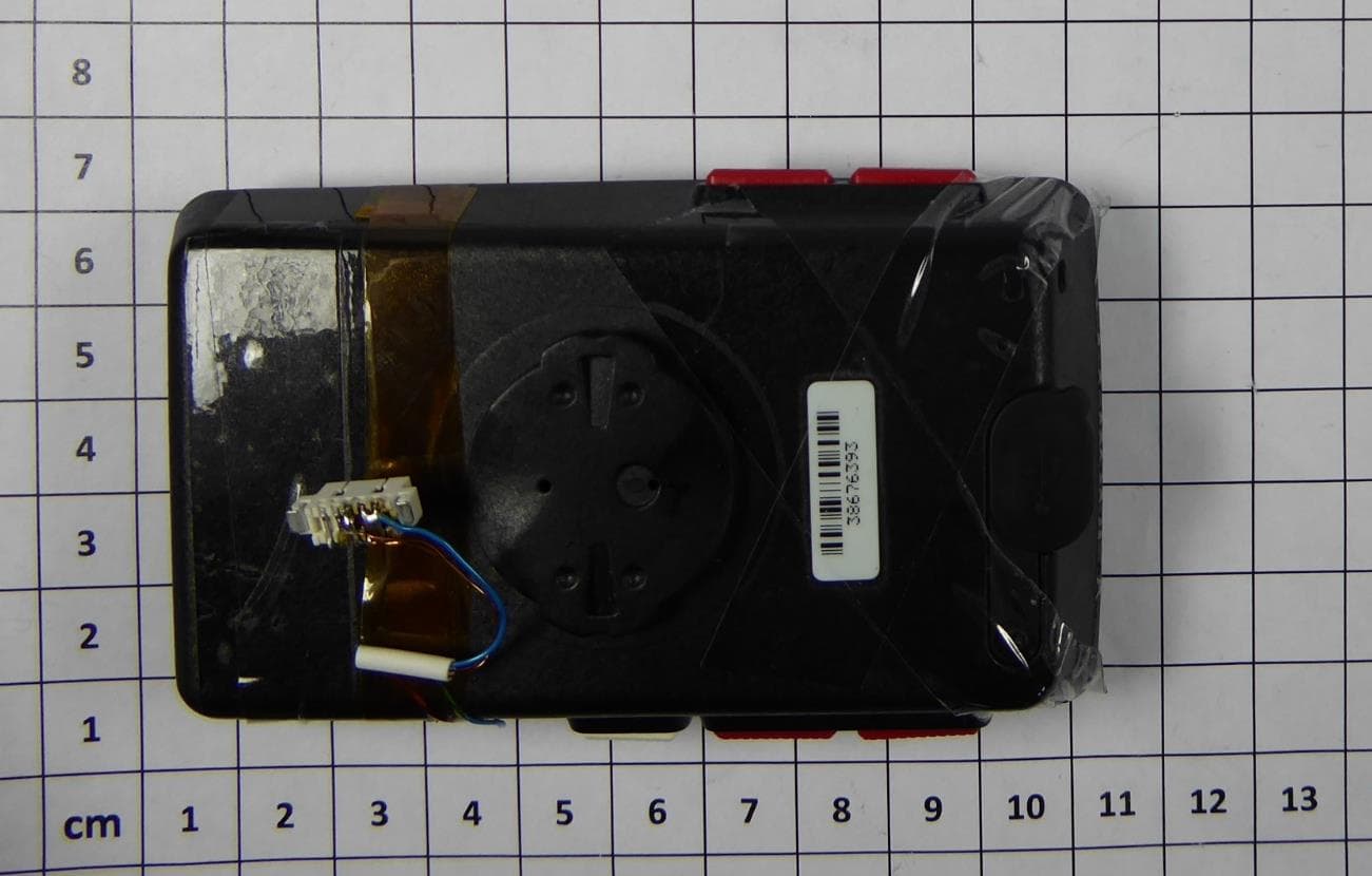
M5LROX-12-1
Apr 20, 2023Bicycle Computer
Equipment Class
JAB - Part 15 Class B Digital Device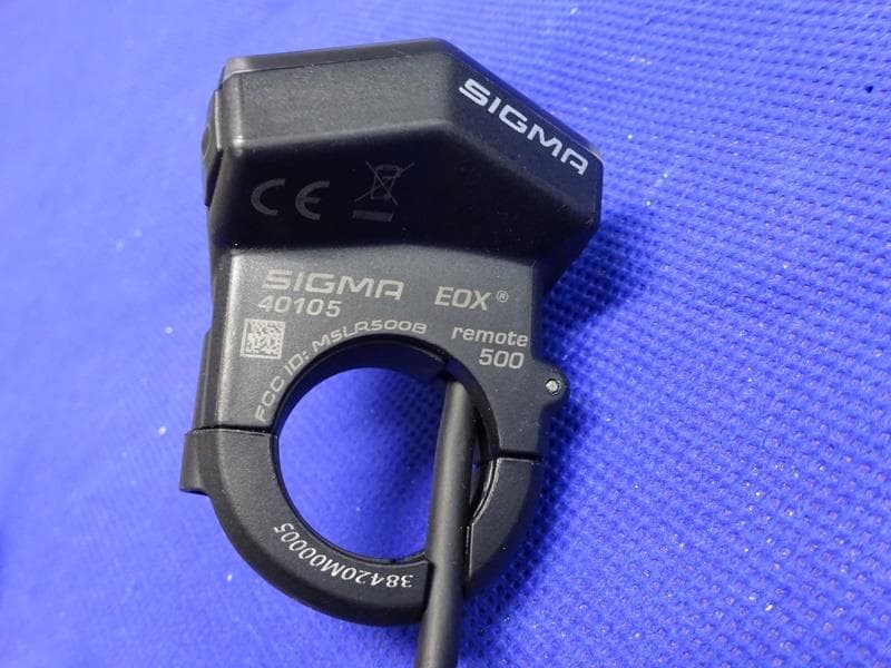
M5LR500B
Jul 11, 2021E-bike Remote with Bluetooth Low Energy
Equipment Class
DTS - Digital Transmission System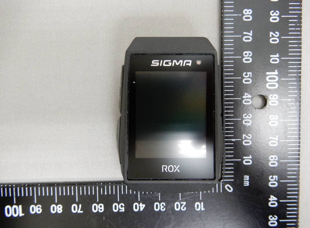
M5LROX111
Mar 03, 2021ROX 11.1 EVO
Equipment Class
DTS - Digital Transmission System
M5LMLSC1
Mar 01, 2021DUO Magnetless SPD/CAD Sensor
Equipment Class
DTS - Digital Transmission System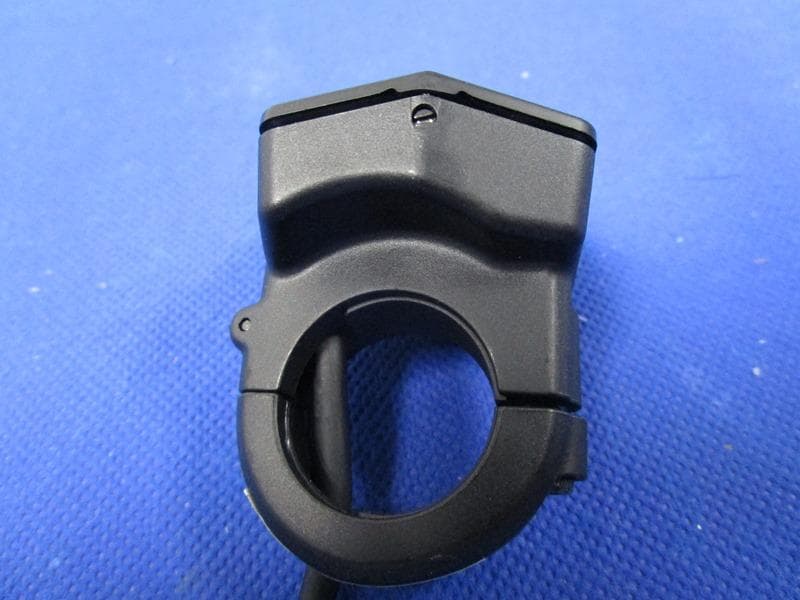
M5LR500
Jan 21, 2021E-bike Remote with Bluetooth
Equipment Class
DTS - Digital Transmission System