M696800VGA Card
Sparkle Computer Co Ltd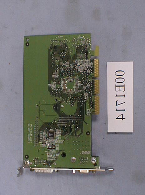
Click to zoom
Application Details
- Equipment Class
- JBP - Part 15 Class B Computing Device Peripheral
- Date of Grant
- Dec 28, 2000
- Application Purpose
- Original Equipment
- Date of Application
- Dec 28, 2000
- Equipment Note
- VGA Card
- Company
- Sparkle Computer Co Ltd
- Country
- Taiwan
Documents & Files
Document Text
Text extracted from the exhibit documents filed with the FCC. Open a document above to read the original.
Users Manual
NVIDIA GeForce2 MX 3D GRAPHIC ACCELERATOR MANUAL 1 NVIDIA GeForce2 MX User’s Manual 1. NVIDIA GeForce2 MX........................................................................................................2 1.1 NVIDIA GeForce2 MX Features.............................................................................2 2. GeForce2 MX Board Outline..............................................................................................3 2.1 GeForce2 MX using SDRAM (SP6800 REV:1)......................................................3 2.2 GeForce2 MX using SDRAM (SP6800 REV:P38).................................................3 3. Hardware installation..........................................................................................................4 3.1 Package Contents...................................................................................................4 3.2 Installing the card....................................................................................................4 3.3 Micro Cross DVI Connector System.......................................................................5 3.4 Resolutions and colors supported:..........................................................................6 4. Smart Installation................................................................................................................7 5. Manually install Windows 95 & Windows 98 drivers..........................................................9 5.1 Installation and Setup..............................................................................................9 5.1.1 Windows95...............................................................................................9 5.1.2 Windows98...............................................................................................9 5.1.3 Windows NT 4.0.....................................................................................10 5.1.4 Windows 2000........................................................................................11 5.2 How to Change Color Depth and Resolution.........................................................12 5.3 How to Change Refresh Rate...............................................................................12 Warning:.....................................................................................................................14 Trademark Acknowledgments..............................................................................................14 2 1. NVIDIA GeForce2 MX Memory Size: SP6800 GeForce2 MX 32MB on Board with SDRAM 1.1 NVIDIA GeForce2 MX Features KEY FEATURES • NVIDIA shading rasterizer • 4 texels per clock • Integrated second-generation Transform and Lighting engines • 256-bit 3D and 2D graphics accelerator • 32-bit color with 32-bit z/stencil • Cube environment mapping • DirectX and S3TC texture compression • 700-Mtexel fill rate • 20 Mtriangles/sec setup • 2.8 GB/second memory bandwidth • Memory Support 2MX32 SDRAM to 32MB • 350 MHz Palette-DAC • AGP 4X • HW Anti-aliasing • Multi-texture and multi-pass • Reflection maps • Single pass multi-texture HIGH-PERFORMANCE 256-BIT 2D ACCELERATION • Optimized for multiple color depths including 32,24,16,15 and 8-bit per pixel. • True-color hardware cursor. • Multi-buffering (double,triple quad buffering) for smooth animation and video playback. COMPREHENSIVE SYSTEM INTERFACE • AGP 4X, 2X and 1X support. • Windows 2000, Windows NT 4.0 display drivers. • Windows 98 and Windows 95 display drivers. • DirectDraw, Direct3D, DirectVideo, ActiveX • OpenGL I for Windows 95, Windows 98, Windows 2000, Windows NT and Linux. • Out-put device TV-OUT or DVI-Connect (optional , only for SP6800 REV:P38) 3 2. GeForce2 MX Board Outline 2.1 GeForce2 MX using SDRAM (SP6800 REV:1) 32M on board DB15 14.318MHZ 2.2 GeForce2 MX using SDRAM (SP6800 REV:P38) 32M on board DVI VIDEO DB15 14.318MHZ NOTE 1: TV output connector and encoder are reserved for optional NOTE 2: DVI connector and LCD encoder are reserved for optional BIOS Nvidia GeForce2 MX 2M*322M*32 2M*322M*32 BIOS Nvidia GeForce2 MX 2M*322M*32 2M*322M*32 SiI 164 4 3. Hardware installation 3.1 Package Contents 1. NVIDIA GeForce2 MX 3D Accelerator card 2. CD title or Software diskettes 3. This manual 3.2 Installing the card 1. Turn off your computer 2. Remove the cover of the computer per the owner’s manual 3. Install the card in the AGP bus slots 4. Replace the cover. 5 3.3 Micro Cross DVI Connector System “Micro Cross:”/high speed pins; C1Analog Red Video Out C2Analog Green Video Out C3Analog Blue Video Out C4Analog Horizontal Sync C5Analog Common Ground Return (Red , Green , Blue Video Out) Note: C1 – C5 Analog signal is not support, just for SPEC. reference Main Pin Field: 1. TMDS Data 2- 2. TMDS Data 2+ 3. TMDS Data 2/4 Shield 4. TMDS Data 4- 5. TMDS Data 4+ 6. DDC Clock 7. DDC Data 8. Analog Vertical Sync 9. TMDS Data 1- 10. TMDS Data1+ 11. TMDS Data1/3 Shield 12. TMDS Data 3- 13. TMDS Data 3+ 14. +5V Power 15. Ground (+5, Analog H/V Sync) 16. Hot Plug Detect 17. TMDS Data 0- 18. TMDS Data 0+ 19. TMDS Data 0/5 Shield 20. TMDS Data 5- 21. TMDS Data 5+ 22. TMDS Clock Shield 23. TMDS Clock 24. TMDS Clock 1 9 17 2 10 18 3 11 19 4 12 20 5 13 21 6 14 22 7 15 23 8 16 24 C1 C2 C4 C5 C3 6 3.4 Resolutions and colors supported: NV11 Bits Per pixel Memory Req. (MB) Refresh Rates (HZ) 81MB60/70/72/75/85/100/120/140/144/150/170/200/240 640*480161MB60/70/72/75/85/100/120/140/144/150/170/200/240 322MB60/70/72/75/85/100/120/140/144/150/170/200/240 81MB60/70/72/75/85/100/120/140/144/170/200/240 800*600161MB60/70/72/75/85/100/120/140/144/170/200/240 322MB60/70/72/75/85/100/120/140/144/170/200/240 81MB60/70/72/75/85/100/120/140/144/150/170/200/240 1024*768162MB60/70/72/75/85/100/120/140/144/150/170/200/240 324MB60/70/72/75/85/100/120/140/144/150/170/200 81MB60/70/72/75/85/100/120/140/144/150/170/200 1152*864162MB60/70/72/75/85/100/120/140/144/150/170/200 324MB60/70/72/75/85/100/120/140/144/150 82…
Text truncated - open the document above for the full version.
External Photos
Photo # 1 Front View Photo # 2 Rear View Photo # 3 Side View Photo # 4 Rear View Photo # 5 Front View Photo # 6 Rear View
ID Label/Location Info
2. Product Labeling 2-1. FCC ID label FCC ID:M696800 0.5 cm The remained portion of label statement required by FCC is attached in the user’s manual. 2-2 Location of Label on EUT 4cm
Internal Photos
Photo # 1 Front View Photo # 2 Rear View Photo # 3 Side View Photo # 4 Rear View Photo # 5 Front View Photo # 6 Rear View
Test Report
NEUTRON EMC LAB. FCC ID: M6968∅∅ 1/24 MEASUREMENT/TECHNICAL REPORT APPLICTNT: Sparkle Technology Co., Ltd. MODEL NO.: SP6800 FCC ID: M6968∅∅ This report concerns ( check one ) : Original Grant ̧ Class II Change Equipment type: VGA Card Deferred grant requested per 47CFR 0.457(d)(1)(ii)? Yes No ̧ If yes, defer until: (date) We, the undersigned, agree to notify the Commission by (date) / / of the intended date of announce ment of the product so that the grant can be issued on that date. Transiyion Rules Request per 15.37? Yes No ̧ If no, assumed Part 15, Subpart B for unintentional radiator the new 47 CFR (10-1-90 Edition) provision. Report Prepared by Testing House : Neutron Engineering Inc. for Company Name: Sparkle Technology Co., Ltd. Address: 13F, No. 2, Sec. 1, Fu Hsing S. Rd., Taipei, Taiwan, R.O.C. Applicant Signature : Jack Hsiao/ Manager NEUTRON EMC LAB. FCC ID: M6968∅∅ 2/24 CERTIFICATION We hereby certify that: The test data , data evaluation , test procedures, and equipment configurations shown in this report were made in accordance with the procedures given in ANSI C63.4 (1992)/ CISPR22(1996) and the energy emitted by the sample EUT tested as described in this report is in compliance with CLASS B conducted and radiated emission limits of FCC Rules Part 15, Subpart B/ CISPR22(1996). Prepared by:Carol Chen Reviewed by:Vincent Su Approved by:George Yao Issued Date :Oct. 23, 2000 Report No. :NEI-FCCB-00133 Company Stamp: NEUTRON ENGINEERING INC. No. 132-1, Lane 329, Sec. 2, Palain Rd., Shijr Jen, Taipei, Taiwan TEL : (02) 2646-5426 FAX : (02) 2646-6815 NEUTRON EMC LAB. FCC ID: M6968∅∅ 3/24 Table of Contents 1. General Information...................................................................................................................... 1-1 Product Description................................................................................................................4 1-2 Related Submittal(s)/Grant(s)..................................................................................................4 1-3 Tested System Details.............................................................................................................5 1-4 Test Methodology...................................................................................................................6 1-5 Test Facility............................................................................................................................6 2. System Test Configuration............................................................................................................ 3-1 Justification.............................................................................................................................7 3-2 EUT Exercise Software...........................................................................................................7 3-3 Special Accessories.................................................................................................................8 3-4 Equipment Modifications.........................................................................................................8 3-5 Configuration of Tested System...............................................................................................9 Figure 3-1 Configuration of Tested System....................................................................................11 3. Block Diagram(s)............................................................................................................................12 4. Conducted Emission Datas............................................................................................................13 5. Radiated Emission Datas .............................................................................................................. 7-1 Radiated Emission Data...........................................................................................................17 7-2 Field Strength Calculation.......................................................................................................21 7-3 Correction Factor Table VS Frequency....................................................................................22 6.Attachment..................................................................................................................................... Photos of Tested EUT.......................................................................................................................23 User’s Manual...................................................................................................................................24 NEUTRON EMC LAB. FCC ID: M6968∅∅ 4/24 1. GENERAL INFORMATION 1-1. Product Description The Sparkle Technology Co., Ltd. Model: SP6800 (referred to as the EUT in this report) is a VGA Card 32MB on Board with SDRAM. The summarized feature of EUT as following: l NVIDIA shading rasterizer l 4 texels per clock l Integrated second-generation Transform and Lighting engines l 256-bit 3D and 2D graphics accelerator l Fully compliant support for OpenGL 1.2 for all Windows operating systems and Linux. l 32-bit color with 32-bit z/stencil l Cube environment mapping l DirectX and S3TC texture compression l 700-Mtexel fill rate l 20 Mtriangles/sec setup l 2.8 GB/second memory bandwidth l Memory Support 2MX32 SDRAM to 32MB l 350 MHz Palette-DAC l AGP 4X l HW Anti-aliasing l Multi-texture and multi-pass l Reflection maps l Single pass multi-texture l Optimized for multiple color depths including 32,24,16,15 and 8-bit per pixel. l Ture-color hardware cursor. l Multi-buffering(double, triple quad buffering)for smooth animation and video playback. l AGP 4X, 2X and 1X support. l Windows 2000, Windows NT4.0 display drivers. l Windows 98 and Windows 95 display drivers. l DirectDraw, Direct3D, DirectVideo, ActiveX l OpenGL 1 for Window 95, Windows 98, Windows 2000, Windows NT and Linux. A. Out-put device TV-OUT or DVI-Connect(optio…
Text truncated - open the document above for the full version.
Test Setup Photos
5-2. Radiated Measurement Photos Mode : CRT Monitor 5-2. Radiated Measurement Photos Mode : LCD Monitor 5-2. Radiated Measurement Photos Mode : TV
Test Setup Photos
5. Conducted and Radiated Measurement Photos 5-1. Conducted Measurement Photos Mode : CRT Monitor 5. Conducted and Radiated Measurement Photos 5-1. Conducted Measurement Photos LCD Monitor 5. Conducted and Radiated Measurement Photos 5-1. Conducted Measurement Photos Mode : TV
Contact Information
Applicant
Jack Hsiao(Manager)
886 2 2741-1196Fax: 886 2 2711-7692
Test Firm
Neutron Engineering Inc.George Yao
Technical Specifications
| # | Rule Parts | Frequency Range | Power Output |
|---|---|---|---|
| 1 | 15B | - | - |
Other Applications from Sparkle Computer Co Ltd
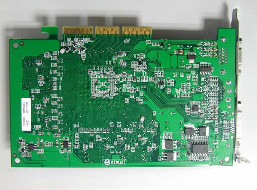
M698836
Apr 14, 2004VGA Card
Equipment Class
JBP - Part 15 Class B Computing Device Peripheral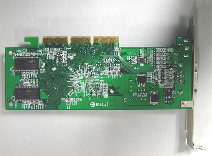
M697310
Mar 30, 2004VGA Card
Equipment Class
JBP - Part 15 Class B Computing Device Peripheral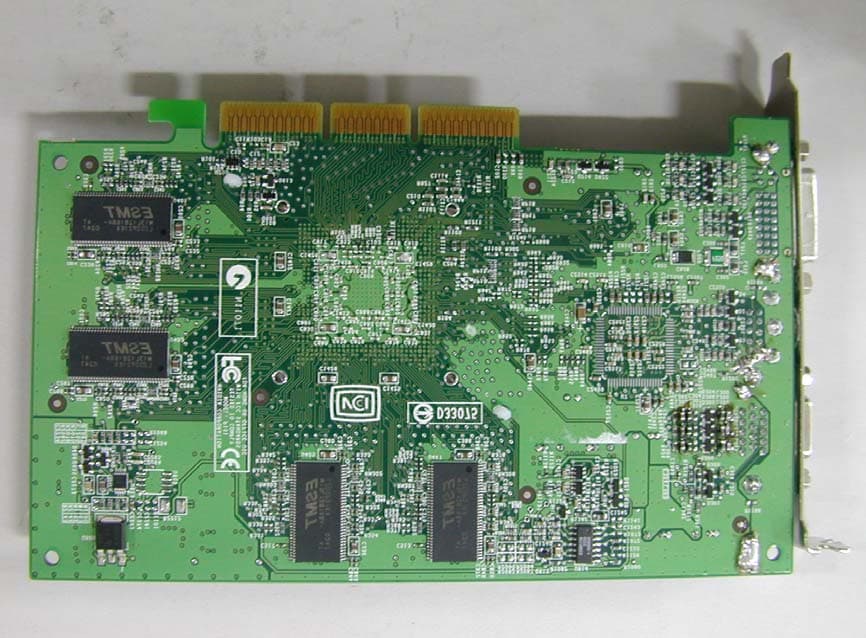
M697228T2
Feb 04, 2003VGA Card
Equipment Class
JBP - Part 15 Class B Computing Device Peripheral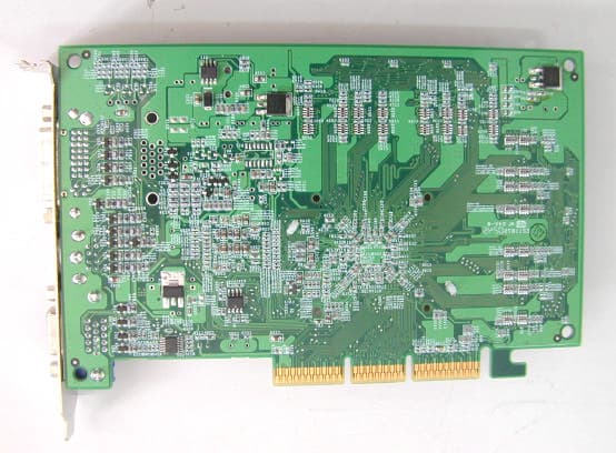
M697300M4
Feb 04, 2003VGA Card
Equipment Class
JBP - Part 15 Class B Computing Device Peripheral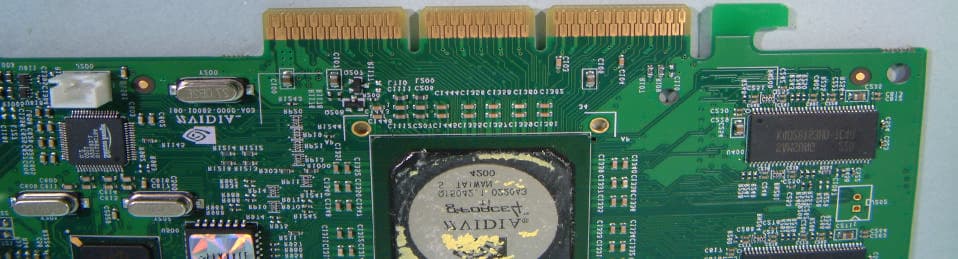
M697200T2
Dec 30, 2002VGA Card
Equipment Class
JBP - Part 15 Class B Computing Device Peripheral