M74T1200
Long Range Solutions, LLC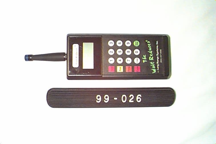
Click to zoom
Application Details
- Equipment Class
- DSC - Part 15 Security/Remote Control Transmitter
- Date of Grant
- Nov 05, 1998
- Application Purpose
- Original Equipment
- Date of Application
- Sep 22, 1998
- Frequency Range
- 448.00000000 - 448.00000000
- Company
- Long Range Solutions, LLC
- Country
- United States
Documents & Files
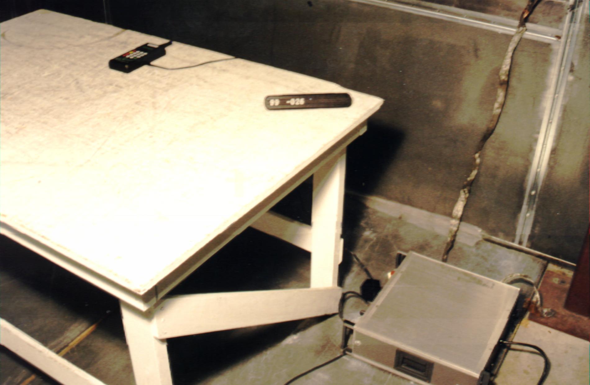
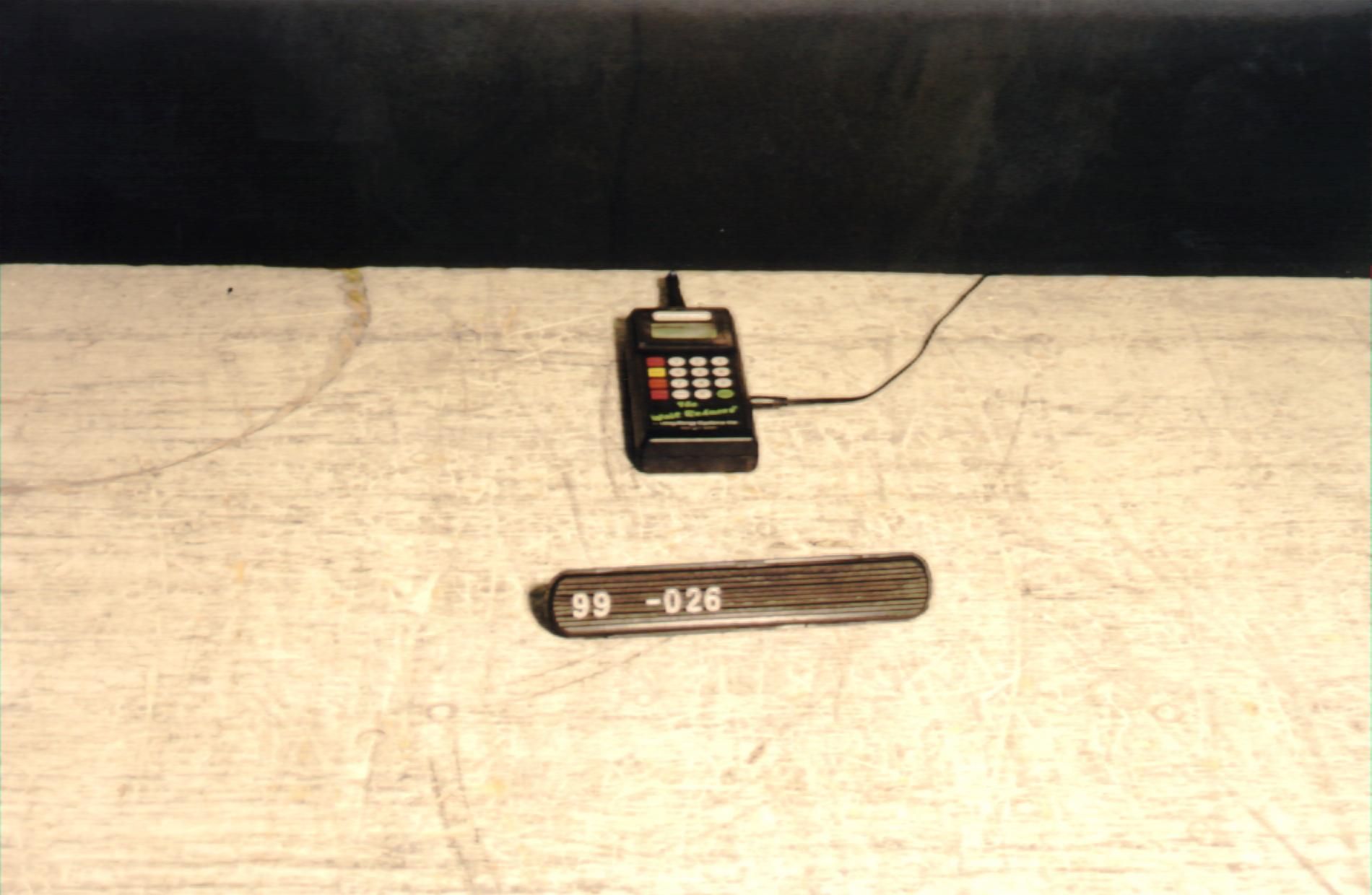
Document Text
Text extracted from the exhibit documents filed with the FCC. Open a document above to read the original.
Users Manual
Modification or changes to this unit which have not been approved by Long Range Systems Inc. can void the user's authority to legally operate this equipment. For information regarding changes or modifications to the equipment, please contact Long Range Systems.
Block Diagram
FCC ID: M74T1200
Cover Letter(s)
August 24, 1998 Federal Communications Commission Authorization & Evaluation Division 7435 Oakland Mills Road Columbia, Maryland 21046 Subject: Type Certification Application: FCC ID M74T1200 To Whom It May Concern: Long Range Systems Inc. hereby authorizes Professional Testing (EMI) Inc. of Round Rock, Texas to operate on its behalf in the matter of FCC approval of the Long Range Systems T1200 Wait Reducer This item is a short range pager transmitter. Professional Testing has evaluated this item and found it to meet the technical requirements of 47 CFR Part 15, Subpart B (Section 15.231). Professional Testing is authorized to file the necessary forms, exhibits and fees required to facilitate this application. If you have any further questions, please contact me: Mr. Kenneth Lovegreen President [email protected] (214) 553-5308 (office) (214) 221-0160 (FAX) 1-800-437-4996 ANTI-DRUG CERTIFICATION Long Range Systems Inc. certifies that no party to this application (as defined in 47 C.F.R. §1.2002(b)(2) ) is subject to a denial of federal benefits pursuant to Section 5301 of the Anti-Drug Abuse Act of 1988, 21 U.S.C 853a. _____________________________________________________________ DateSignature Title Long Range Systems Inc. Long Range Systems Inc.Long Range Systems Inc. Long Range Systems Inc. 10840 Switzer #107 10840 Switzer #10710840 Switzer #107 10840 Switzer #107 Dallas , Texas 75238 Dallas , Texas 75238Dallas, Texas 75238 Dallas , Texas 75238
ID Label/Location Info
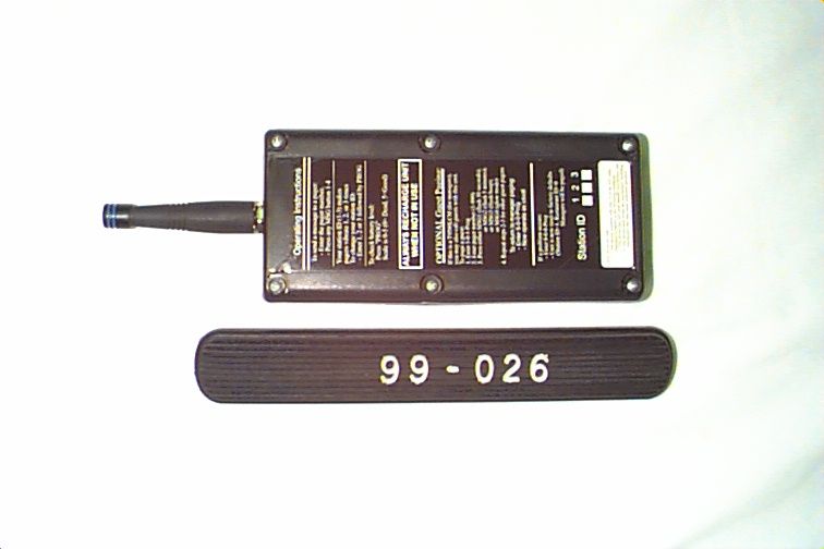
LABEL LOCATION (BOTTOM REAR OF EUT) Antenna FCC ID: M74T1200 This device complies with Part 15 of the FCC rules. Operation is subject to the following conditions: 1 This device may not cause harmful interference, and 2 This device must accept any interference, including interference that may cause undesired operation.
Operational Description
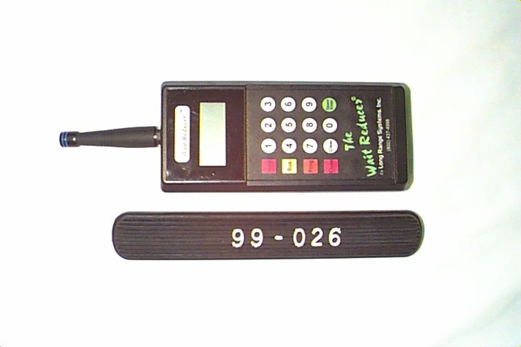
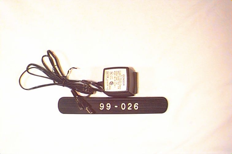
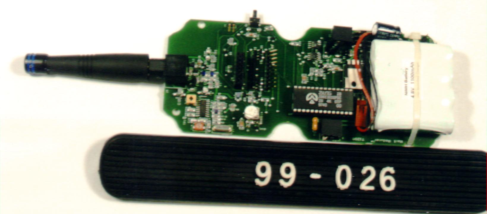
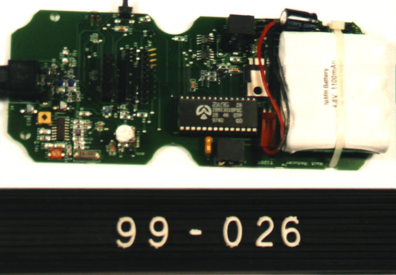
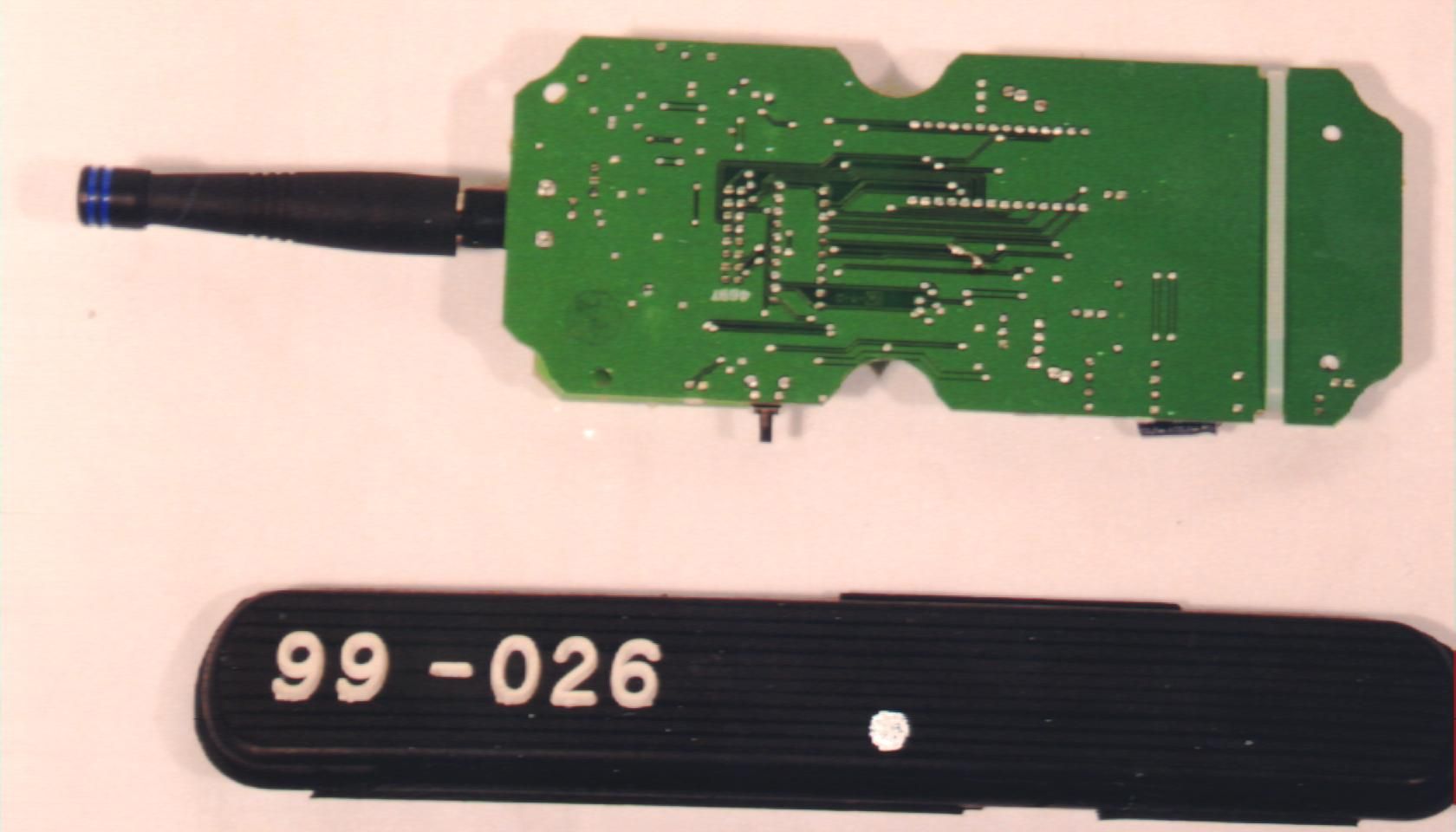
FCC ID M74T1200 PRODUCT AND OPERATIONAL DESCRIPTION: LONG RANGE SYSTEMS T1200 WAIT REDUCER PAGER TRANSMITTER 1.0 General Description The Long Range Systems T1200 Wait Reducer Pager Transmitter is a handheld device used for transmitting paging calls to small (belt worn) battery powered pagers. This device is intended for use by restaurants to inform patrons that their table is ready. Only one T1200 is used in each system configuration. The T1200 is battery powered, but can also operated from an AC to DC power adapter. To call a pager, the operator inputs the pager code into the T1200 from the front panel then presses the CALL button. The code is then transmitted to the pager. The T1200 is in ‘sleep mode’ most of the time and is only active when the front panel keys are pressed and the code is transmitted. After the code has been tranmitted, the unit goes back into sleep mode automatcially. 2.0 Wireless Description Wireless transmission for the T1200 is compliant with the requirements of Section 15.231 of the Rules. The EUT transmits at 448.00 MHz and uses AM modulation for the code stream. A simple chipset is used for code and modulation construction and a Motorola Synthesizer (MC13176) is used as the RF source and modulator. A transimpedance amplifier is used to drive the integrated antenna. A 3 inch monopole (which is permanently attached to the main board) is used as the antenna. No operator tuning or alignment of the T1200 is possible or required. Due to the power limitations of Section 15.231, the range of the T1200 is limited (a few hundred feet maximum). This is satisfactory for the intended use of the device. The frequency of transmission was determined to prevent interference with other (long range pager services.
Operational Description
STATEMENT OF MICHAEL A. NICOLAY In Connection With APPLICATION FOR CERTIFICATION Radi-Can R/C RECEIVER FCC ID: AEK980249R I am an Engineer, an employee in the firm of Carl T. Jones Corporation, with offices located in Springfield, Virginia. My education and experience are a matter of record with the Federal Communications Commission. All of the measurements contained in this test report were performed by me or under my supervision, and I attest to the accuracy of each. I submit that, to the best of my knowledge, the test sample meets the technical standards set forth in the Commission's Part 15 Rules and Regulations. DATED: October 21, 1998 Michael A. Nicolay Carl T. Jones Corporation 7901 Yarnwood Court Springfield, VA 22153 (703) 569-7704 [email protected]
Operational Description
1 FCC INFORMATION INQUIRY RESPONSE FCC ID M74T1200, SUBMISSION ID: EA91844 November 4, 1998 Correspondence ID: 4418 This information is provided in request to an inquiry regarding the Type Certification Application for the Long Range Systems T1200 Wait Reducer Transmitter. The inquiry is provided in response provided by Mr. Joe Dichoso of the Commission on November 4, 1998. Question/Inquiry: Indicate the length of the ID code. Is it of fixed length? 2,3,4 bits? If the ID code is of fixed length pertaining to a fixed number of pagers/receivers it is not considered data. Answer: The transmission length for the Wait Reducer Transmitter is fixed. The transmission is 7 bytes long with each byte being an 8 bit word. Most of the bytes are synchronization (2 bytes) with Bytes # 3, 4 and 5 being the Table/pager ID code. Byte #6 is a stop/command byte indicating that the ID code has been completed. A Checksum byte (Byte 7) is used at the end of the message to maintain the total transmission length at a fixed number of bits (bit inserted as needed to maintain a fixed message length). The total transmission length never changes.
Test Report
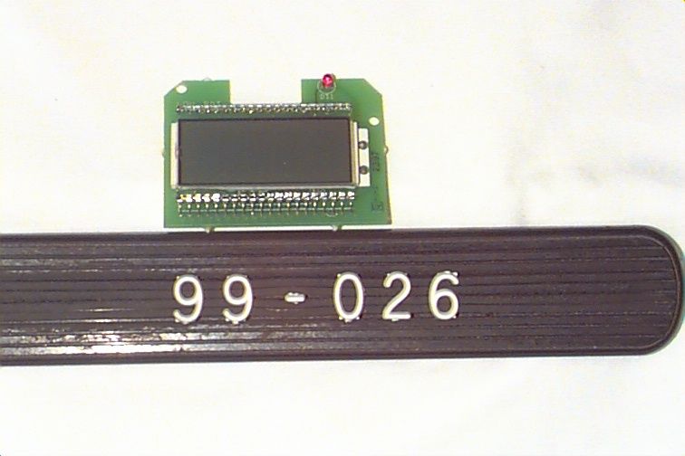
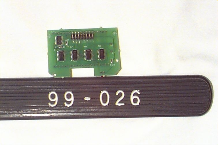
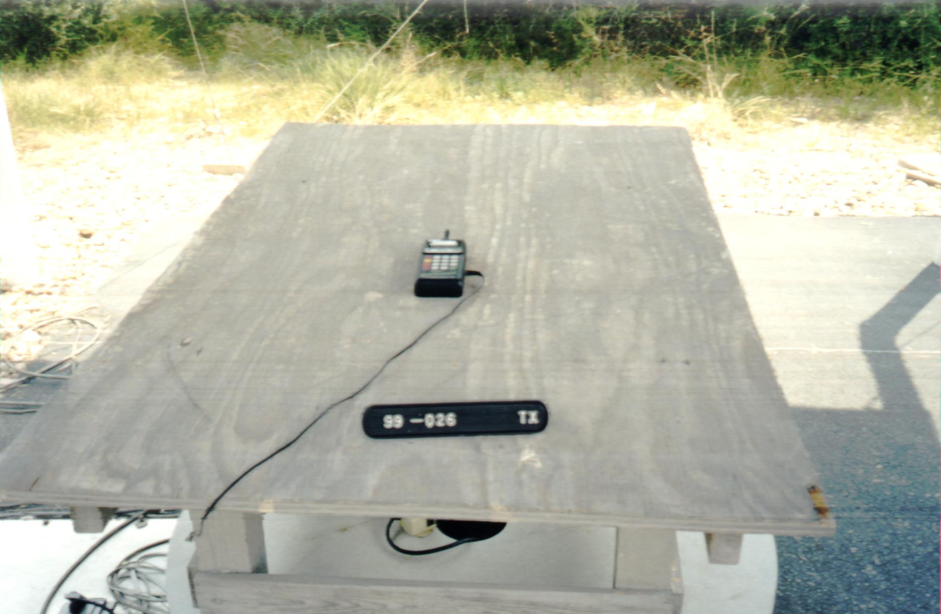
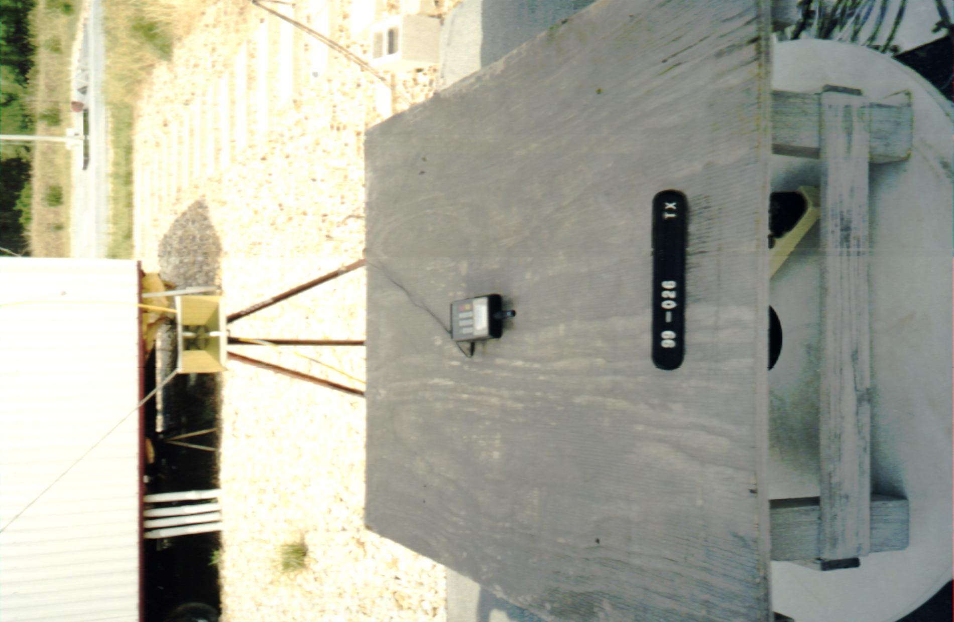
FCC ID: M74T1200 Prepared for: LONG RANGE SYSTEMS INC. 10840 Switzer, #107 Dallas, Texas 75238 By: Professional Testing (EMI), Inc. 1601 FM 1460, Suite B Round Rock, Texas 78664 PTI PROJECT: 99-026 Submitted to: Federal Communications Commission Equipment Authorization Division, Application Processing Branch 7435 Oakland Mills Road Columbia, MD 21048 September 1998 FCC Type Certification Test Report of an Intentional Radiator LONG RANGE SYSTEMS INCORPORATED T1200 Wait Reducer Pager Transmitter (Transmitter Portion) FCC ID# M74T1200 Professional Testing (EMI), Inc.2 of 25 Table of Contents Title Page ..............................................................................................................................................1 Table of Contents...................................................................................................................................2 Certificate of Compliance......................................................................................................................4 Appendices...........................................................................................................................................3 1.0Equipment Under Test (EUT) Description..................................................................................5 1.1Equipment Under Test (EUT) Operation.....................................................................................5 2.0Operational Frequency Measurement and EUT Use Evaluation.................................................5 2.1Test Procedure..............................................................................................................................6 2.2Test Criteria..................................................................................................................................6 2.3Test Results...................................................................................................................................6 3.0Deactivation Measurements.........................................................................................................6 3.1Test Procedure..............................................................................................................................6 3.2Test Criteria..................................................................................................................................6 3.3Test Results...................................................................................................................................7 4.0Occupied Bandwidth Measurements...........................................................................................7 4.1Test Procedure..............................................................................................................................7 4.2Test Criteria..................................................................................................................................7 4.3Test Results...................................................................................................................................7 5.0Peak Output Power.......................................................................................................................8 5.1Test Procedure..............................................................................................................................8 5.2Test Criteria..................................................................................................................................8 5.3Test Results...................................................................................................................................9 6.0Out-of-Band and Restricted Band Emissions Measurements......................................................9 6.1Test Procedure..............................................................................................................................9 6.2Test Criteria..................................................................................................................................9 6.3Test Results.................................................................................................................................10 7.0Conducted Emissions Measurements.........................................................................................10 7.1Test Procedure............................................................................................................................10 7.2Test Criteria................................................................................................................................10 7.3Test Results.................................................................................................................................10 8.0Antenna Requirement.................................................................................................................11 8.1Evaluation Procedure..................................................................................................................11 8.2Evaluation Criteria......................................................................................................................11 8.3Evaluation Results......................................................................................................................11 9.0Form 731 Information................................................................................................................11 9.1Emission Designator...................................................................................................................11 9.2Output Power..............................................................................................................................12 9.3Main Processor Chip..................................................................................................................13 10.0List of Test Equipment.......…
Text truncated - open the document above for the full version.
Contact Information
Applicant
Robert Pinell
Technical Contact
Long Range Systems Inc.Kenneth Lovegreen
[email protected](214) 553-5308
10840 Switzer · Dallas, Texas · United States
Non-Technical Contact
Long Range Systems Inc.Kenneth Lovegreen
[email protected](214) 553-5308
Test Firm
Professional Testing (EMI) Inc.Jeffrey Lenk
Technical Specifications
| # | Rule Parts | Frequency Range | Power Output |
|---|---|---|---|
| 1 | 15C | 448 MHz - 448 MHz | - |
Other Applications from Long Range Solutions, LLC

M74-6863
Dec 13, 2012Table Tracker
Equipment Class
DTS - Digital Transmission System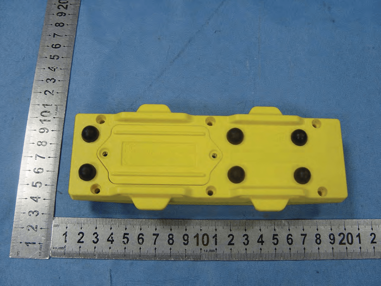
M745629
May 10, 2012Beach Bulter xp
Equipment Class
DSC - Part 15 Security/Remote Control Transmitter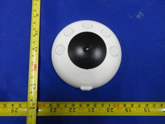
M74PRONTO
Feb 12, 2012PRONTO
Equipment Class
DSC - Part 15 Security/Remote Control Transmitter
M74TGUHF
Jul 20, 2011Table Genie UHF
Equipment Class
DSC - Part 15 Security/Remote Control Transmitter
M74T1505
Mar 24, 2004Wireless Low Power Medical Paging Transmitter
Equipment Class
DSC - Part 15 Security/Remote Control Transmitter