M7N-BW8370Z-Extender
Remotec Technology Limited
Click to zoom
Application Details
- Equipment Class
- DXX - Part 15 Low Power Communication Device Transmitter
- Date of Grant
- Feb 06, 2011
- Application Purpose
- Original Equipment
- Date of Application
- Feb 06, 2011
- Equipment Note
- Z-Extender
- Frequency Range
- 908.40000000 - 908.40000000
- Company
- Remotec Technology Limited
- Country
- Hong Kong
Documents & Files
Document Text
Text extracted from the exhibit documents filed with the FCC. Open a document above to read the original.
Users Manual
1 Z-Extender TM ZXT-300 ( Z-Wave-to-IR Extender) Operating Instructions Introduction ZXT-300 works with any Z-Wave compliant controller or gateway translating Z-Wave’s Simple AV command to IR control code. User is able to set the IR code and using the larger code library of ZXT-300. It is capable to use the learning function of ZXT-300 through the simple UI on gateway or Z-Wave remote controller. It is allow to download the preset/learnt commands from gateway or Z-Wave remote controller to ZXT-300. User can enjoy the fully wireless control in anywhere at home. Figure 1 ZXT-300 2 ZXT-300 Operations Before using the ZXT-300, please read the [INSTALLATION] if it is need to mount the ZXT-300 to a wall. Power up the ZXT-300 by the supplied AC/DC adaptor. L CAUTION − Be sure to always use the supplied AC/DC adaptor. − Do not try to power up other device with the supplied AC/DC adaptor. This could damage the AC/DC adaptor or the connected device. Configurations Figure 2 PROG Key and IR Ports of ZXT-300 IR Learnin g LED Indication IR Port 1 IR Port Out put “PROG” button 3 Change Z-Wave-to-IR Channel (EP) on ZXT-300 Step Setup Key LED Indication Status on ZXT-300 1 Press and hold PROG button on the ZXT-300 for 3seconds to switch the EP (1->2->3->4- >5->6->1->2...) • LED flashes 1 = EP1 • LED flashes 2 = EP2 • LED flashes 3 = EP3 • LED flashes 4 = EP4 • LED flashes 5 = EP5 • LED flashes 6 = EP6 How to get the NIF “Node Information Frame” on ZXT- 300 Step Setup Key LED Indication Status on ZXT-300 1 ZXT-300 switch to Z-Wave-to- IR Channel (EP1) • LED flashes 1 times then keep on 2 Press the PROG button on the ZXT-300 (EP1 will response “NIF” EP2, EP3, EP4, EP5, EP6 will response “Multi-channel capability report”) • LED flashes 1 times then keep on (ZXT-300 will report the supported command class) Reset ZXT-300 to factory default Press and hold “PROG” button for 10seconds on ZXT-300. LED will flashing until reset process is completed. 4 INSTALLATION MOUNTING THE ZXT-300 TO A WALL MOUNTING LOCATION PRECAUTIONS • Before mounting, check the material and structure of the mounting location. If the location does not have the proper material or structure, the ZXT-300 can fall and cause an injury. • Use commercial items that best match the wall structure and material for the screws and other fixtures. • Do not mount near a kitchen counter, humidifier, or other location in which it can be exposed to smoke or steam. Doing so could cause a fire or electrical shock. • Do not mount in locations with high humidity or large amounts of dust. Doing so could cause a fire or electrical shock. • Do not mount to locations subject to high temperatures, high humidity, or exposed to water. Doing so could cause a fire or electrical shock. • Do not mount to locations subject to large amounts of vibration, large jolts, or large forces. These could cause an injury if the ZXT- 300 falls and breaks. MOUNTING PROCEDURE PRECAUTIONS • Do not modify parts or use the ZXT-300 in ways other than its intended use. Doing so could cause the ZXT-300 to fall and result in an injury. • Be sure to fully check that there are no electrical wires or pipes inside the wall before mounting. • If any of the screws are loose, the ZXT-300 can fall and cause an injury. Do not mount the ZXT-300 with the screws still loose. • Check that the two screws mounted to the wall are fully inserted into the key holes of the ZXT-300. Otherwise, the ZXT-300 can fall and cause an injury. • Do not mount the ZXT-300 so that it sticks out from the wall edge. It could get hit by people’s bodies or objects and cause an injury. • Remotec will not be liable for any accidents or injuries that occur due to improper mounting or handling. • When mounting, be careful not to get your fingers pinched or injure your hands. MOUNTING PROCEDURE The ZXT-300 can be mounted to a wall or wooden racks using the two key holes in the bottom case. The ZXT-300 can be oriented horizontally or vertically. Mount in the best way for your installation conditions. Note 1: The reception sensitivity varies depending on the antenna direction. Find the direction providing the best reception by adjusting the antenna direction before mounting the ZXT-300. 5 Note 2: No screws are provided for mounting to a wall. Note 3: Before mounting to a wall, be sure to fully read the precautions. 1. Obtain two screws suitable for the wall strength and material. The screw size is shown in the figure below. 2. The positional relationship between the ZXT-300 key holes and the screw mounting positions are shown in the figure below. Note 1: When mounting the screws to the wall, leave a space between the wall and screw cap as shown in the figure. 3. Insert the ZXT-300 key holes onto the two screws mounted to the wall, and then slide downward to secure in place. 4. After securing the ZXT-300 to the wall, connect the AC/DC adaptor and cables to the ZXT-300. Note 1: Check that the ZXT-300 is firmly secured to the wall. Note 2: Insert the AC/DC adaptor and IR emitter cable so that they are firmly connected to the ZXT-300. 5. When removing the ZXT-300 from the wall, lift up the ZXT-300, then pull it towards you. 6 WIRELESS INFORMATION Wireless range: This device has an open air line of sight transmission distance of 100 feet which complies with the Z-Wave standards. Performance can vary depending on the amount of objects in between Z-Wave devices such as walls and furniture. Every Z-Wave device set up in your house will act as a signal repeater allowing devices to talk to each other and find alternate routes in the case of a reception dead spot. Radio frequency limitations: 1. Each wall or object (i.e.: refrigerator, bookshelf, large TV, etc) can reduce the maximum range of 65 feet by up to 25 to 30%. 2. Plasterboard and wooden walls block less of the radio signal then concrete, brick or tile walls which will have more of an effect on signal strength. 3. Wall mounted Z-Wave devices will also suffer a loss of range as they are h…
Text truncated - open the document above for the full version.
External Photos
External Photo Top View of the product Bottom View of the product Front View of the product Rear View of the product Left view of the product Right view of the product IR Emitting Cable AC/DC adaptor
ID Label/Location Info
BW8370US TM Z-Extender 300US DC IN 5V 100mA This device complies with Part 15 of the FCC Rules. Operation is subject to the following two conditions: (1) this device may not cause harmful interference, and (2) this device must accept any interference received, including interference that may cause undesired operation. FCC ID: M7N-BW8370 908.4MHz US MADE IN CHINA F-BW8370US 34x31.5mm BW8370US TM Z-Extender 300US DC IN 5V 100mA This device complies with Part 15 of the FCC Rules. Operation is subject to the following two conditions: (1) this device may not cause harmful interference, and (2) this device must accept any interference received, including interference that may cause undesired operation. FCC ID: M7N-BW8370 908.4MHz US MADE IN CHINA
Internal Photos
Internal photo Internal view of the product Inner Circuit Top View Inner Circuit Bottom View Antenna
Test Report
TEST REPORT No.: (5210)350-0812 BUREAU VERITAS HONG KONG LIMITED – Kowloon Bay Office 1/F Pacific Trade Centre, 2 Kai Hing Road, Kowloon Bay, Kowloon,HONG KONG Tel: +852 2331 0888 Fax: +852 2331 0889 www.cps.bureauveritas.com This report is intended for your exclusive use. Any copying or replication of this report to or for any other person or entity, or use of our name or trademark, is permitted only with our prior written permission. Our report is limited to the test samples identified herein. The results set forth in this report are not necessarily indicative or representative of the statistical quality or characteristics of the lot from which a test sample was taken or any similar or identical product unless specifically and expressly noted. Our report includes all of the tests requested by you and the results thereof. You shall have thirty days from receipt of this report to request additional testing of the samples or to notify us of any errors or omissions relating to our report, provided, however, such notice shall be in writing and shall specifically address the issue you wish to raise. A failure to raise such issue within the prescribed time shall constitute your unqualified acceptance of the completeness of this report, the tests conducted and the correctness of the report contents. Page 2 of 21 Location of the test laboratory Radiated and Conducted emissions measurements are investigated and taken pursuant to the procedures of ANSI C63.4 – 2003. An Open Area Test Site and Full Anechoic Chamber (FCC Listed Site, Registration No. 642151) are set up for investigation and located at : BUREAU VERITAS HONG KONG LIMITED, EMC CENTRE No. 2106-2107, 21/F., Westin Centre, 26 Hung To Road, Kwun Tong, Kowloon, Hong Kong List of measuring equipment Radiated Emission EQUIPMENT MANUFACTURER MODEL NO. SERIAL NO. CALIBRATION DUE EMI TEST RECEIVER R&S ESCI 100379 06-SEP-2011 LOOP ANTENNA ETS-LINDGREN 6502 00102266 17-MAY-2011 BILOG ANTENNA SCHAFFNER CBL6112D 25229 02-AUG-2011 OPEN AREA TEST SITE BVCPS N/A N/A 05-JUL-2011 ANECHOIC CHAMBER ALBATROSS M-CDC 80374004499B 26-OCT-2011 COAXIAL CABLE SUHNER N/A N/A 19-SEP-2011 Conducted Emission EQUIPMENT MANUFACTURER MODEL NO. SERIAL NO. CALIBRATION DUE EMI TEST RECEIVER R&S ESCS30 830986/030 13-DEC-2011 LISN R&S ENV216 100024 09-MAR-2011 Remarks:- N/A : Not Applicable or Not Available The measurement instrumentation uncertainty would be taking into consideration on each of the test result TEST REPORT No.: (5210)350-0812 BUREAU VERITAS HONG KONG LIMITED – Kowloon Bay Office 1/F Pacific Trade Centre, 2 Kai Hing Road, Kowloon Bay, Kowloon,HONG KONG Tel: +852 2331 0888 Fax: +852 2331 0889 www.cps.bureauveritas.com This report is intended for your exclusive use. Any copying or replication of this report to or for any other person or entity, or use of our name or trademark, is permitted only with our prior written permission. Our report is limited to the test samples identified herein. The results set forth in this report are not necessarily indicative or representative of the statistical quality or characteristics of the lot from which a test sample was taken or any similar or identical product unless specifically and expressly noted. Our report includes all of the tests requested by you and the results thereof. You shall have thirty days from receipt of this report to request additional testing of the samples or to notify us of any errors or omissions relating to our report, provided, however, such notice shall be in writing and shall specifically address the issue you wish to raise. A failure to raise such issue within the prescribed time shall constitute your unqualified acceptance of the completeness of this report, the tests conducted and the correctness of the report contents. Page 3 of 21 Equipment Under Test [EUT] Description of Sample: Model Name: Z-Extender TM Model Number: BW8370US Additional Model Name: BW8371US, BW8372US, BW8373US, BW8374US Additional Model Information: Declare the Circuit, PCB layout and Electrical parts of the products are identical to the basic model, except the model number. Rating: 100-240Va.c., 50/60Hz – 5Vd.c. (AC/DC adaptor) Description of EUT Operation: The Equipment Under Test (EUT) is a REMOTEC TECHNOLOGY LTD. of Remote Control Transceiver. It is a 1-button transceiver and operating at 908MHz. The EUT continues to transmit while buttons is being pressed, Modulation by IC, and type is pulse modulation. The transceiver has different control: 1. PROG button – transmission on Antenna Requirement (Section 15.203) The EUT is use of a permanently antenna. It is soldered on the PCB. The antenna is not replaceable or user serviceable. The requirement of S15.203 are met. There are no deviations or exceptions to the specifications. Photo of Antenna TEST REPORT No.: (5210)350-0812 BUREAU VERITAS HONG KONG LIMITED – Kowloon Bay Office 1/F Pacific Trade Centre, 2 Kai Hing Road, Kowloon Bay, Kowloon,HONG KONG Tel: +852 2331 0888 Fax: +852 2331 0889 www.cps.bureauveritas.com This report is intended for your exclusive use. Any copying or replication of this report to or for any other person or entity, or use of our name or trademark, is permitted only with our prior written permission. Our report is limited to the test samples identified herein. The results set forth in this report are not necessarily indicative or representative of the statistical quality or characteristics of the lot from which a test sample was taken or any similar or identical product unless specifically and expressly noted. Our report includes all of the tests requested by you and the results thereof. You shall have thirty days from receipt of this report to request additional testing of the samples or to notify us of any errors or omissions relating to our report, provided, however, such notice shall be in writing and shall specifically address the issue you wish to raise. A failure to raise such issue within the prescribed time shall constitute your unqualifi…
Text truncated - open the document above for the full version.
Test Setup Photos
Test set-up photo Measurement of Radiated Emission Test Set Up Measurement of Conducted Emission Test Set Up
Contact Information
Applicant
Yang Liu(Engineering manager)
Test Firm
Bureau Veritas Hong Kong LimitedSteven Tsang
[email protected]85223310728
Technical Specifications
| # | Rule Parts | Frequency Range | Power Output |
|---|---|---|---|
| 1 | 15C | 908.4 MHz - 908.4 MHz | - |
Other Applications from Remotec Technology Limited

M7N-BW8493
Feb 07, 2023ZXT-800US
Equipment Class
DXX - Part 15 Low Power Communication Device Transmitter
M7N-BW8510
Nov 24, 2015Scene Master
Equipment Class
DXX - Part 15 Low Power Communication Device Transmitter
M7N-BW8377
Jul 15, 2014Z-Wave to AC IR Extender
Equipment Class
DXT - Part 15 Low Power Transceiver, Rx Verified
M7N-BW8030US
Jun 20, 2012Zwave Thermostat
Equipment Class
DXX - Part 15 Low Power Communication Device Transmitter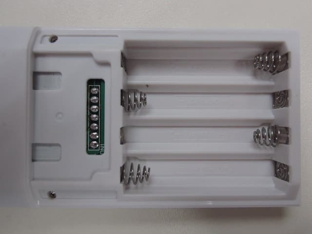
M7N-BW8380
Apr 18, 2012Z-Wave Remote Controller
Equipment Class
DXX - Part 15 Low Power Communication Device Transmitter