M7N-BW8377Z-Wave to AC IR Extender
Remotec Technology Limited
Click to zoom
Application Details
- Equipment Class
- DXT - Part 15 Low Power Transceiver, Rx Verified
- Date of Grant
- Jul 15, 2014
- Application Purpose
- Original Equipment
- Date of Application
- Jul 15, 2014
- Equipment Note
- Z-Wave to AC IR Extender
- Frequency Range
- 908.42000000 - 908.42000000
- Company
- Remotec Technology Limited
- Country
- Hong Kong
Documents & Files
Document Text
Text extracted from the exhibit documents filed with the FCC. Open a document above to read the original.
Users Manual
ZXT-120 (Z-Wave-to-AC IR Extender) USER MANUAL Table of Contents Introduction2 Controller and Gateway Requirements3 Built-in IR code library3 Glossary3 Product Overview5 Setup and Operations6 Listening Mode6 Inclusion/Exclusion7 IR Code Selection8 IR Code Learning9 Reset ZXT-120 to factory default14 ZXT-120 Information14 Z-Wave Configuration Parameters15 Installation18 Mounting the ZXT-120 to a wall18 Wireless Information21 Maintenance21 Frequently Asked Questions22 Technical Specifications24 Checking Accessories25 FCC Notice 25 Warnings26 Caution26 1 TM Z-ExtenderZXT-120 (Z-Wave-to-AC IR Extender) Introduction The ZXT-120 is a Z-Wave to IR extender for air-conditioner (AC), (Figure 1), it works with any Z-Wave compliant gateway or controller by translating Z-Wave Thermostat Commands to AC IR control code. User can select the IR code from the built-in code library of ZXT-120, or use learning function, by using Z-Wave Configuration Commands according to the parameter table. ZXT-120 is also with built-in temperature sensor which allows gateway or controller to get the current room temperature. ZXT-120 can be configured as either "Frequently Listening Routing Slaves" FLiRS (if you are using battery) or "Always Listening" (if you are using 5Vdc adaptor) before inclusion process. Refer to Glossary for definition of "FLiRS" and "Always Listening" mode. ZXT-120 supports Network Wide Inclusion (NWI) and Explore Frames. It also supports Z- ]Wave networks with multiple gateways and controllers. Once the configuration and setup is complete, the gateway or controller can use Z-Wave "Thermostat commands class" to control their IR-controlled air-conditioner through the ZXT-120. 2 Figure 1 ZXT-120 3 Controller and Gateway Requirements The ZXT-120 can work with any Z-Wave compliant controller or gateway supporting the following Z-Wave commands. -Configuration Command Class -Multilevel Sensor Command Class -Thermostat Command Class >Thermostat Mode Command Class >Thermostat Fan Mode Command Class > Thermostat Set-point Command Class Built-in IR code library The Built-in IR code library supports most of the popular air conditioner brands in the market. Z-Wave gateway and controller does not need to have any IR control code knowledge. User can use Z-Wave controller or gateway to select the IR code according to the ZXT-120 code list separately provided through Z-Wave configuration command. Glossary Device or Node Devices and nodes are all terms to describe an individual Z- Wave device. These are all interchangeable when setting up your Z-Wave network. Inclusion Add a Z-Wave device to the network. Exclusion Delete a Z-Wave device to the network. Remove To take a device out of a group, scene or association group while that device still exists in the same Z-Wave network. 4 Z-Wave Network A collection of Z-Wave devices is controlled by primary and secondary controllers operating on the same system. A Z-Wave network has its own unique ID code so that controllers not in the network cannot control the system. Primary Controller The first controller is used to set up your devices and network. Only the Primary Controller can be used to include or delete devices from a network. It is recommended that you mark the primary controller for each network for ease in modifying your network. Network Wide Inclusion (NWI) Network Wide Inclusion (NWI) enables both end-user friendly, Plug and Play like Z-Wave network installation as well as professional installation scenario where the inclusion process in terms of time will be reduced significantly. NWI is a feature supported by a new frame type named Explorer which enables the Z-Wave protocol to implement Adaptive Source Routing. FLiRS Mode FLiRS is abbreviation for "Frequently Listening Routing Slave". FLiRS mode is targeted for battery operated applications and will enter sleep mode frequently in order to conserve battery consumption. The response to Z-Wave command is not as quick as Always Listening Device. Normally there is 1-2 seconds latency. Always Listening Mode Always Listening mode is targeted for AC power operated applications and it can act as a repeater, which will re-transmit the RF signal to ensure that the signal is received by its intended destination by routing the signal around obstacle and radio dead spots. The response to Z-Wave command is immediate. Product Overview 1."PROG" Button, Learning and LED Indication 2.Temperature sensor 3.External IR Port 4.USB Power 5V DC 5.Battery chassis 5 Surround IR Output for top and 4-directions Figure 2 PROG Key and IR Port of ZXT-120 12 34 5 6 Setup and Operations Before using the ZXT-120, please read the [INSTALLATION] if you need to mount the ZXT-120 to a wall. Power up the ZXT-120 by the USB Power 5Vdc or Dry battery AAA x 3pcs. -Plug-in 5Vdc power into the USB socket if operated at Always Listening mode. Or -Install 3xAAA batteries if operated at FLiRS mode. -Please refer to the section of [MOUNTING PROCEDURE]. -Remove the battery cover on the back of your ZXT-120 battery chassis. -Mount the battery cover into the main unit with 2 screws. -Check the polarity of the batteries and the "+/-" marks inside the battery compartment. -Insert the batteries. -Push the battery cover and main unit back in place. (Please carefully read through the following then store the manual for future reference.) Listening Mode (default mode is FLiRS) ZXT-120 can be configured as either "Frequently Listening Routing Slaves" FLiRS (if you are using battery) or "Always Listening" (if you are using 5Vdc adaptor) before inclusion process. Refer to Glossary for definition of "FLIRS" and "Always Listening" mode. Important: It is not allowed to changing ZXT-120 listening mode without exclusion process (do not change ZXT-120 listening mode while ZXT-120 is included in a network). ƒ{-Use new batteries of the recommended type and size only. ƒ{-Never mix used and new batteries together. ƒ{-To avoid chemical leaks, remove batteries from the ZXT-120 if …
Text truncated - open the document above for the full version.
External Photos
www.tuv.com Test Report No.: 14036228 001 Appendix 3 page 1 of 4 Appendix 3 EUT External Photos www.tuv.com Test Report No.: 14036228 001 Appendix 3 page 2 of 4 External View External View www.tuv.com Test Report No.: 14036228 001 Appendix 3 page 3 of 4 External View External View www.tuv.com Test Report No.: 14036228 001 Appendix 3 page 4 of 4 External View External View
ID Label/Location Info
Scale 2:1 BW8377US DC IN 5V 100mA DC 4.5V AAAx3 908.42MHz ZXT-120US This device complies with Part 15 of the FCC Rules. Operation is subject to the following two conditions: (1) this device may not cause harmful interference, and (2) this device must accept any interference received, including interference that may cause undesired operation. FCC ID: M7N-BW8377 BW8377US DC IN 5V 100mA DC 4.5V AAAx3 908.42MHz ZXT-120US This device complies with Part 15 of the FCC Rules. Operation is subject to the following two conditions: (1) this device may not cause harmful interference, and (2) this device must accept any interference received, including interference that may cause undesired operation. FCC ID: M7N-BW8377
Internal Photos
www.tuv.com Test Report No.: 14036228 001 Appendix 4 page 1 of 3 Appendix 4 EUT Internal Photos www.tuv.com Test Report No.: 14036228 001 Appendix 4 page 2 of 3 Internal View Internal View www.tuv.com Test Report No.: 14036228 001 Appendix 4 page 3 of 3 Internal View Internal View
Test Report
www.tuv.com Test Report No.: 14036228 001 Date: 27.06.2014 page 2 of 13 Table of Content Page Cover Page .................................................................................1 Table of Content ..........................................................................2 Test Summary ................................................................................................................ 4 Product information....................................................................................................... 5 Manufacturers declarations ....................................................................................................................... 5 Product function and intended use ........................................................................................................... 5 Submitted documents ................................................................................................................................. 5 Independent Operation Modes .................................................................................................................. 5 Related Submittal(s) Grants ....................................................................................................................... 5 Remark ......................................................................................................................................................... 5 Test Set-up and Operation Mode .................................................................................. 6 Principle of Configuration Selection ......................................................................................................... 6 Test Operation and Test Software ............................................................................................................. 6 Special Accessories and Auxiliary Equipment ......................................................................................... 6 Countermeasures to achieve EMC Compliance ....................................................................................... 6 Test Methodology .......................................................................................................... 7 Radiated Emission ...................................................................................................................................... 7 Field Strength Calculation .......................................................................................................................... 7 List of Test and Measurement Instruments ................................................................. 8 Results FCC Part 15 – Subpart C ................................................................................. 9 Subclause 15.203 – Antenna Information ....................................................................... Pass ................. 9 Subclause 15.207 – Conducted Emission on AC Mains ................................................ Pass ................. 9 Subclause 15.215 (c) – 20 dB Bandwidth ........................................................................ Pass ............... 10 Subclause 15.249 (a) – Radiated Emission (Fundamental and Harmonics) ................ Pass ............... 10 Subclause 15.205, 15.249 (d) – Spurious Radiated Emissions ..................................... Pass ............... 11 Results FCC Part 15 – Subpart B ............................................................................... 12 Subclause 15.107 – Conducted Emission on AC Mains ................................................ Pass ............... 12 Subclause 15.109 – Spurious Radiated Emissions ....................................................... Pass ............... 13 Appendix 1 – Test Results 15 pages Appendix 2 – Test Setup Photos 3 pages www.tuv.com Test Report No.: 14036228 001 Date: 27.06.2014 page 3 of 13 Appendix 3 – EUT External Photos 4 pages Appendix 4 – EUT Internal Photos 3 pages Appendix 5 – Label, Operational Description, Block, Schematics and User Manual 35 pages www.tuv.com Test Report No.: 14036228 001 Date: 27.06.2014 page 4 of 13 Test Summary Conducted Emissions Result: Pass 20dB bandwidth Result: Pass Radiated Emission of Carrier Frequency Result: Pass Spurious Radiated Emissions Result: Pass www.tuv.com Test Report No.: 14036228 001 Date: 27.06.2014 page 5 of 13 Product information Manufacturers declarations Transceiver Operating frequency range 908.42 MHz Type of modulation GFSK Number of channels 1 Type of antenna Integral Power level fix Connection to public utility power line No Nominal voltage V nor : 5.0 Vdc (USB) and/ or 4.5Vdc (3 x 1.5V AAA) Product function and intended use The equipment under test (EUT) is a Z-wave transceiver operating at 908.42 MHz. It is powered by 5.0 Vdc (USB) and/ or 4.5Vdc (3 x 1.5V AAA batteries). The USB port is used for power supply only. FCC ID: M7N-BW8377 Models Product description BW8377US Z-wave transceiver Submitted documents Circuit Diagram Block Diagram Bill of material User manual Rating Label Independent Operation Modes The basic operation modes are: - Z-wave communication link maintained with data transfer. For further information refer to User Manual Related Submittal(s) Grants This is a single application for certification of the transmitter. The receiving portion is authorized under the verification procedure. Remark - None. www.tuv.com Test Report No.: 14036228 001 Date: 27.06.2014 page 6 of 13 Test Set-up and Operation Mode Principle of Configuration Selection Emission: The equipment under test (EUT) was configured to measure its highest possible radiation level. The test modes were adapted accordingly in reference to the instructions for use. Test Operation and Test Software Test operation should refer to test methodology. - There was no special software to exercise the device. Special Accessories and Auxiliary Equipment The product has been tested together with the following additional acce…
Text truncated - open the document above for the full version.
Test Report
www.tuv.com Test Report No.: 14036228 001 Appendix 1 page 1 of 15 Appendix 1 Test Results www.tuv.com Test Report No.: 14036228 001 Appendix 1 page 2 of 15 Conducted Emission TX frequency: 908.42MHz AC mains Neutral www.tuv.com Test Report No.: 14036228 001 Appendix 1 page 3 of 15 TX frequency: 908.42MHz AC Mains Live www.tuv.com Test Report No.: 14036228 001 Appendix 1 page 4 of 15 RX Mode AC Mains Neutral www.tuv.com Test Report No.: 14036228 001 Appendix 1 page 5 of 15 RX Mode AC Mains Live www.tuv.com Test Report No.: 14036228 001 Appendix 1 page 6 of 15 20dB Bandwidth Tx frequency: 908.42MHz A 908.496 MHz Ref -30.6 dBm 908.496 MHz Att 0 dB 908.496 MHz * 908.496 MHz SWT 5 ms 908.496 MHz Center 908.42 MHz 908.496 MHz Span 500 kHz 908.496 MHz 50 kHz/ 908.496 MHz * 908.496 MHz RBW 10 kHz 908.496 MHzVBW 30 kHz 908.496 MHz 1 PK 908.496 MHz VIEW 908.496 MHz 908.496 MHz 908.496 MHz 908.496 MHz 908.496 MHz 908.496 MHz 908.496 MHz 908.496 MHz 908.496 MHz 908.496 MHz -130 -120 -110 -100 -90 -80 -70 -60 -50 -40 908.496 MHz 1 Marker 1 [T1 ] -36.54 dBm 908.394000000 MHz 2 Marker 2 [T1 ] -56.54 dBm 908.349000000 MHz 3 Marker 3 [T1 ] -57.11 dBm 908.496000000 MHz D1 -56.54 dBm MARKER 3 908.496 MHz Date: 25.JUN.2014 15:19:48 www.tuv.com Test Report No.: 14036228 001 Appendix 1 page 7 of 15 Radiated Emission Tx frequency: 908.42MHz 9k – 30MHz www.tuv.com Test Report No.: 14036228 001 Appendix 1 page 8 of 15 Tx frequency: 908.42MHz 30MHz – 1000MHz (Horizontal) www.tuv.com Test Report No.: 14036228 001 Appendix 1 page 9 of 15 Tx frequency: 908.42MHz 30MHz – 1000MHz (Vertical) www.tuv.com Test Report No.: 14036228 001 Appendix 1 page 10 of 15 Tx frequency: 908.42MHz 1GHz – 10GHz (Horizontal) www.tuv.com Test Report No.: 14036228 001 Appendix 1 page 11 of 15 Tx frequency: 908.42MHz 1GHz – 10GHz (Vertical) www.tuv.com Test Report No.: 14036228 001 Appendix 1 page 12 of 15 Rx mode 30MH – 1GHz (Horizontal) www.tuv.com Test Report No.: 14036228 001 Appendix 1 page 13 of 15 Rx mode 30MH – 1GHz (Vertical) www.tuv.com Test Report No.: 14036228 001 Appendix 1 page 14 of 15 Rx mode 1GHz – 2GHz (Horizontal) www.tuv.com Test Report No.: 14036228 001 Appendix 1 page 15 of 15 Rx mode 1GHz – 2GHz (Vertical)
Test Setup Photos
www.tuv.com Test Report No.: 14036228 001 Appendix 2 page 1 of 3 Appendix 2 Test Setup Photos www.tuv.com Test Report No.: 14036228 001 Appendix 2 page 2 of 3 Setup for radiated emission Setup for radiated emission www.tuv.com Test Report No.: 14036228 001 Appendix 2 page 3 of 3 Setup for radiated emission Setup for conducted emission
Contact Information
Applicant
Yang Liu(Engineering manager)
Technical Contact
TUV Rheinland Hong Kong LimitedBenny Lau
[email protected]0085221921000
8-10/F., Goldin Financial Global Square · Kowloon · Hong Kong
Non-Technical Contact
TUV Rheinland Hong Kong LimitedBenny Lau
[email protected]0085221921000
Test Firm
Global United Technology Service Co., LtdRobinson Lo
Technical Specifications
| # | Rule Parts | Frequency Range | Power Output |
|---|---|---|---|
| 1 | 15C | 908.42 MHz - 908.42 MHz | - |
Other Applications from Remotec Technology Limited

M7N-BW8493
Feb 07, 2023ZXT-800US
Equipment Class
DXX - Part 15 Low Power Communication Device Transmitter
M7N-BW8510
Nov 24, 2015Scene Master
Equipment Class
DXX - Part 15 Low Power Communication Device Transmitter
M7N-BW8030US
Jun 20, 2012Zwave Thermostat
Equipment Class
DXX - Part 15 Low Power Communication Device Transmitter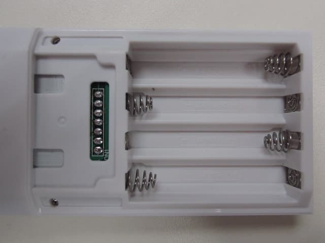
M7N-BW8380
Apr 18, 2012Z-Wave Remote Controller
Equipment Class
DXX - Part 15 Low Power Communication Device Transmitter
M7N-BW8370
Feb 06, 2011Z-Extender
Equipment Class
DXX - Part 15 Low Power Communication Device Transmitter