M7N-BW8380Z-Wave Remote Controller
Remotec Technology Limited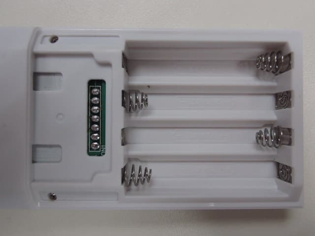
Click to zoom
Application Details
- Equipment Class
- DXX - Part 15 Low Power Communication Device Transmitter
- Date of Grant
- Apr 18, 2012
- Application Purpose
- Original Equipment
- Date of Application
- Apr 18, 2012
- Equipment Note
- Z-Wave Remote Controller
- Frequency Range
- 908.40000000 - 908.40000000
- Company
- Remotec Technology Limited
- Country
- Hong Kong
Documents & Files
Document Text
Text extracted from the exhibit documents filed with the FCC. Open a document above to read the original.
Users Manual
1 ZRC-100 (Z-Wave Remote Control) 2 Table of Contents Introduction .................................................... 4 Glossary .......................................................... 5 ZRC-100 Operations ....................................... 6 Configurations ................................................. 7 Description of Function Keys .............................. 7 Add/Delete Devices .......................................... 8 Device Control ................................................. 11 Scene Setup ................................................... 12 Scene Control ................................................. 15 Comfort Control .............................................. 16 Sensor Information ......................................... 17 Device Configure ............................................. 17 Sensor Configure ............................................ 19 Comfort / Sensor Configure ............................. 22 Short Key ...................................................... 24 Z-Wave Advanced Setup ................................. 26 Learning Mode ................................................ 26 Configure Association ...................................... 28 Change Device Configuration ............................ 34 Resetting Your Network..................................... 36 System Settings .............................................. 37 About ZRC-100 ................................................ 39 Z-Wave Network Setup ................................... 40 Rediscover Network ......................................... 40 Re-scan (Rediscover) Devices from network ....... 41 Delete Dead Node from Network ....................... 43 Listening Mode................................................. 44 Create a Secondary Controller ........................... 45 Create a Primary Controller ............................... 46 WIRELESS INFORMATION ............................... 48 MAINTENANCE................................................. 48 FREQUENTLY ASKED QUESTIONS .................... 48 Z-Wave Frequently Asked Questions ................... 48 TECHNICAL SPECIFICATIONS.......................... 51 CHECKING THE ACCESSORIES ......................... 52 3 FCC NOTICE .................................................... 52 WARNINGS ...................................................... 52 CAUTION ........................................................ 53 4 ZRC-100 (Z-Wave Remote Control) Operating Instructions Introduction The ZRC-100 is a LCD Z-Wave remote controller (Figure 1) and it can work with Z-Wave enabled devices, support multi-channel, thermostat, secure door lock, binary / multi-level sensor command class and controls their on/off or up/down individually, or via a pre-configured Scene and adjust your room temperature. The ZRC-100 give an intelligent LEDs smart guide and LCD display for all setup procedures and operation. User can setup / operate their Z-Wave devices through the LCD and LEDs UI on ZRC-100. User can enjoy integrated wireless control in anywhere at home. Figure 1 ZRC-100 Short cut key 5 Glossary Device or Node Devices and nodes are all terms to describe an individual ZWave device. These are all interchangeable when setting up your Z- Wave network. Inclusion Add a Z-Wave device to the network. Exclusion Delete a Z-Wave device from the network. Remove To take a device out of a group, scene or association group while that device still exists in the same Z-Wave network. Z-Wave Network A collection of Z-Wave devices controlled by primary and secondary controllers operating on the same system. A Z-Wave network has its own unique ID code so that controllers not in the network cannot control the system. Primary Controller The first controller used to set up your devices and network. Only the Primary Controller can be used to include or delete modules from a network. It is recommended that you mark the primary controller for each network for ease in modifying your network. Secondary Controller A controller containing network information about other modules within the network and is used for controlling devices. Secondary controller is created from the Primary Controller and cannot include or delete modules to the network. Inclusion Controller A controller containing network information about other modules within the network and is used for controlling devices. Inclusion controller is created from the Primary Controller in a SIS enabled Z-Wave network. Inclusion Controller has the ability to add and remove devices from the network. Scene A collection of Z-Wave devices configured to turn to a specific level, setting, mode, or perform an operation. Scenes are usually activated by a controller, timed event, or specific conditions. 6 ZRC-100 Operations Welcome to the world of Z-Wave home automation, your ZRC-100 will be able to control all the Z-Wave products around your house. The following section will guide you through the set up processes for your ZRC-100. Please note that all Z-Wave devices, light switches, dimmers, shutter switches, thermostat and secure door lock made from various vendors are compatible with your ZRC-100 as long as they carry the Z-Wave logo: (Please carefully read through the following then store the manual for future reference.) Before using the ZRC-100, please install the batteries: • 4xAAA batteries are required for operation. • Remove the battery cover on the back of your remote. • Check the polarity of the batteries and the "+/-" marks inside the battery compartment. • Insert the batteries. • Push the battery cover back in place. L CAUTION (battery safety) − Use new batteries of the recommended type and size only. − Never mix used and new batteries together. − To avoid chemical leaks, remove batteries from the remote controller if you do not intend to use the remote for an extended period of time. − Dispose of used batteries properly; do not burn or bury them. 7 Configurations Figure 2 Setup and co…
Text truncated - open the document above for the full version.
External Photos
www.tuv.com Appendix 3 Prüfbericht - Nr.: Test Report No.: 14029481 001 Seite 1 von 3 Page 1 of 3 Transceiver Transceiver www.tuv.com Appendix 3 Prüfbericht - Nr.: Test Report No.: 14029481 001 Seite 2 von 3 Page 2 of 3 Transceiver Transceiver www.tuv.com Appendix 3 Prüfbericht - Nr.: Test Report No.: 14029481 001 Seite 3 von 3 Page 3 of 3 Transceiver
ID Label/Location Info
www.tuv.com Appendix 5 Prüfbericht - Nr.: Test Report No.: 14029481 001 Seite 3 von 60 Page 3 of 60 FCC Label and location The yellow oval shows the location of the Rating Label
Internal Photos
www.tuv.com Appendix 4 Prüfbericht - Nr.: Test Report No.: 14029481 001 Seite 1 von 3 Page 1 of 3 Transceiver Transceiver www.tuv.com Appendix 4 Prüfbericht - Nr.: Test Report No.: 14029481 001 Seite 2 von 3 Page 2 of 3 Transceiver Transceiver www.tuv.com Appendix 4 Prüfbericht - Nr.: Test Report No.: 14029481 001 Seite 3 von 3 Page 3 of 3 Transceiver Transceiver
Test Report
www.tuv.com Test Report No.: 14029481 001 Date: 17.04.2012 Page 2 of 13 Test Summary 20dB bandwidth Result: Pass Radiated Emission of Carrier Frequency Result: Pass Spurious Radiated Emissions Result: Pass www.tuv.com Test Report No.: 14029481 001 Date: 17.04.2012 Page 3 of 13 Contents General Remarks ...................................................................................................4 List of Test and Measurement Instruments.........................................................5 General Product Information ................................................................................6 Product Function and Intended Use.............................................................................................6 Ratings and System Details...........................................................................................................6 Independent Operation Modes......................................................................................................7 Submitted Documents ...................................................................................................................7 Related Submittal(s) Grants ..........................................................................................................7 Test Set-up and Operation Mode..........................................................................8 Principle of Configuration Selection ............................................................................................8 Test Operation and Test Software ................................................................................................8 Special Accessories and Auxiliary Equipment ............................................................................8 Countermeasures to achieve EMC Compliance ..........................................................................8 Test Methodology ..................................................................................................9 Radiated Emission..........................................................................................................................9 Field Strength Calculation .............................................................................................................9 Test Results .........................................................................................................10 20dB Bandwidth Section 15.215(c).........................................................................................10 Radiated Emission of Carrier Frequency Section 15.249(a) .................................................11 Spurious Radiated Emissions Section 15.249(a, c, d, e) .......................................................12 Appendix 1: Test Results Appendix 2: Test Setup Appendix 3: EUT External Photo Appendix 4: EUT Internal Photo Appendix 5: Block Diagram, FCCID Label, Schematics and User manual. www.tuv.com Test Report No.: 14029481 001 Date: 17.04.2012 Page 4 of 13 General Remarks Nil. www.tuv.com Test Report No.: 14029481 001 Date: 17.04.2012 Page 5 of 13 List of Test and Measurement Instruments Hong Kong Productivity Council (Registration number: 90656) Equipment Manufacturer Type S/N Due Date Semi-anechoic Chamber Frankonia Nil Nil 25-May-12 Test Receiver R & S ESU40 100190 26-May-12 Bi-conical Antenna R & S HK116 100241 05-May-13 Log Periodic Antenna R & S HL223 841516/020 06-May-13 Coaxial cable 50ohm Rosenberger RTK081-05S- 05S-10m LA2-001-10M / 001 15-Nov-13 Microwave amplifer 0.5- 26.5GHz, 25dB gain HP 83017A 3950M00241 03-Oct-13 High Pass Filter (cutoff freq. =1000MHz) Trilithic 23042 9829213 28-Oct-13 Horn Antenna EMCO 3115 9002-3351 11-May-13 Active Loop Antenna EMCO 6502 9107-2651 19-Apr-12 FSP 30 Spectrum Analyser R & S FSP 30 100007 16-Sep-12 www.tuv.com Test Report No.: 14029481 001 Date: 17.04.2012 Page 6 of 13 General Product Information Product Function and Intended Use The equipment under test (EUT) is a remote control of a home automation system. It is able to control the wireless enabled equipment at the home. It uses 908.4MHz as a communication channel. There is only one frequency channel in this product. FCC ID: M7N-BW8380 Model Product description BW8380US, BW8381US, BW8382US, BW8383US Z-WAVE Remote Controller The four models listed in the above table are identical in construction including mechanical dimension, schematics, PCB layouts and electronic components except a change in Cosmetic. Model BW8380US was selected as a representative for testing. Ratings and System Details Transceiver Operating Frequencies : 908.4MHz Number of channels : 1 Type of antenna : Integral antenna Power supply : 6.0VDC, 4 x AAA size batteries Ports : Nil www.tuv.com Test Report No.: 14029481 001 Date: 17.04.2012 Page 7 of 13 Independent Operation Modes The basic operation modes are: - Control of Z-Wave enabled home electrical products. - Others, please refer to user manual for further details Submitted Documents The submitted documents are listed as follow: - Circuit diagram - Block diagram - User manual - FCC ID label Related Submittal(s) Grants This is a single application for certification of the transceiver. Remarks - www.tuv.com Test Report No.: 14029481 001 Date: 17.04.2012 Page 8 of 13 Test Set-up and Operation Mode Principle of Configuration Selection Emission: The equipment under test (EUT) was configured to measure its highest possible radiation level. The test modes were adapted accordingly in reference to the instructions for use. Test Operation and Test Software Test operation should refer to test methodology. - There was RF test mode to exercise the device. Special Accessories and Auxiliary Equipment The product has been tested together with the following additional accessories: - none Countermeasures to achieve EMC Compliance - none www.tuv.com Test Report No.: 14029481 001 Date: 17.04.2012 Page 9 of 13 Test Methodology Radiated Emission The radiated emission measurements were performed a…
Text truncated - open the document above for the full version.
Test Report
www.tuv.com Appendix 1 Prüfbericht - Nr.: Test Report No.: 14029481 001 Seite 1 von 1 Page 1 of 1 A Att 20 dBRef -10 dBm 1 PK MAXH 200 kHz/Center 908.4 MHzSpan 2 MHz * RBW 100 kHz VBW 300 kHz SWT 2.5 ms PRN -110 -100 -90 -80 -70 -60 -50 -40 -30 -20 -10 1 Marker 1 [T1 ] -27.27 dBm 908.396000000 MHz 2 Delta 2 [T1 ] -20.83 dB 240.000000000 kHz 3 Delta 3 [T1 ] -20.80 dB -224.000000000 kHz Date: 2.APR.2012 06:55:16 20dB Bandwidth
Test Setup Photos
www.tuv.com Appendix 2 Prüfbericht - Nr.: Test Report No.: 14029481 001 Seite 1 von 1 Page 1 of 1 Set-up for Radiated Emission Set-up for Radiated Emission
Contact Information
Applicant
Yang Liu(Engineering manager)
Test Firm
Hong Kong Productivity CouncilIr Angel Wong Yuen-yee
Technical Specifications
| # | Rule Parts | Frequency Range | Power Output |
|---|---|---|---|
| 1 | 15C | 908.4 MHz - 908.4 MHz | - |
Other Applications from Remotec Technology Limited

M7N-BW8493
Feb 07, 2023ZXT-800US
Equipment Class
DXX - Part 15 Low Power Communication Device Transmitter
M7N-BW8510
Nov 24, 2015Scene Master
Equipment Class
DXX - Part 15 Low Power Communication Device Transmitter
M7N-BW8377
Jul 15, 2014Z-Wave to AC IR Extender
Equipment Class
DXT - Part 15 Low Power Transceiver, Rx Verified
M7N-BW8030US
Jun 20, 2012Zwave Thermostat
Equipment Class
DXX - Part 15 Low Power Communication Device Transmitter
M7N-BW8370
Feb 06, 2011Z-Extender
Equipment Class
DXX - Part 15 Low Power Communication Device Transmitter