M8CBDQ25QuieTech Dehumidifier
Fego Precision Industrial Co Ltd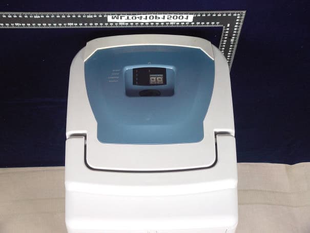
Click to zoom
Application Details
- Equipment Class
- DSC - Part 15 Security/Remote Control Transmitter
- Date of Grant
- Nov 04, 2004
- Application Purpose
- Original Equipment
- Date of Application
- Nov 04, 2004
- Equipment Note
- QuieTech Dehumidifier
- Frequency Range
- 303.85000000 - 303.85000000
- Country
- Taiwan
Documents & Files
Document Text
Text extracted from the exhibit documents filed with the FCC. Open a document above to read the original.
Users Manual
BDQ25 unit function Fego Co .,Ltd :Beennan Date:2004/11/3 ! POWER AC︰120V/60HZ ! RF and receiver function description: Unit will send RF signal to receiver tell it unit status for user can know the unit status . This RF signal will send every 15 second. KEYBOARD FUNDTION ● MODE/POWER button operate description: ★ Dehumidifiers have five five operating mode︰Economy,Continuous,45%- 55% humidity-setting,55%-65% humidity- setting、Off mode。 ★ Fan speed can’t be adjusted,it operate just only at any mode except Off and tank full situation. ★ Pressing MODE/POWER button mode will action after release button one second but choose Off mode it will action after after release button three second. ★ When press and hold MODE/POWER button over 3 second system will enter off mode. If customer press button again it will come to Economy mode. ★ When pressing the MODE/POWER button first time,choose Economy mode and the economy led will on and monitor display the room humidity. ★ When pressing the MODE/POWER button second time,choose Continuous and the Continuous led will on and monitor display the room humidity. ★ When pressing the MODE/POWER key third time,choose 45%-55% humidity-setting,and the “45%-55%” led will on and monitor display the room humidity. ★ When pressing the MODE/POWER key fourth time,choose 55%-65% humidity-setting,and the “55%-65%” led will on and monitor display the room humidity. ★ When pressing the MODE/POWER key fifth time, back to off mode, Mode/Power button led will on and monitor display the room humidity. ● Mode Description: ★ First power plug in : compressor and fan stop , Mode/Power button led will on and monitor display the room humidity. System will check tank full or not. If full ,tank led will flash and have three times beep. At the same time system will check Humidity sensor and temperature sensor and tank full switch install correct not. ★ Economy mode : economy led will on . if room humidity over or equal 65% fan and compressor on(if compressor stop before, it is on at the three minutes safe time, if safe time is not arrive, it wont run. Over the safe time,than it will run) start dehumidity . When the room humidity lower 65%, compressor stop but fan still running when room humidity continue lower 70% within one minute fan will off. But Holmes hope fan stop after running 3 minute. Norm will check BDQ24 function. if humidity is over and >= 70%, turn on the fan, than turn on and the compressor on and have three minutes safe time protection. When tank is full, refer to〔Tank full〕item. ● Continuous mode Continuous led on ,compressor(compressor have 3 minute protection function ) and fan continue running . When tank is full, turn off the compressor but fan is going on, after one minute if still tank full then fan off. Continuous led still on and display room humidity. Tank is full description please refer to 〔Tank full〕item. ● 45%-55% mode: 45%-55% led on. When room humidity is over or equal 45%, then compressor(compressor have 3 minute protection function ) and fan continue running. When the room humidity is lower 45%, turn off the compressor but fan still running(Please check does fan stop after running 3 minute). If the room humidity continue lower 50% within one minute then fan off. If humidity is over or equal 50%, then compressor(compressor have 3 minute protection function ) and fan continue running. When the room humidity is lower 45%, turn off the compressor but fan still running(Please check does fan stop after running 3 minute). If the room humidity continue lower 50% within one minute then fan off. When tank is full, refer to 〔Tank full〕item. ● 55%-65% mode 55%-65% led on. When room humidity is over or equal 55%, then compressor(compressor have 3 minute protection function ) and fan continue running. When the room humidity is lower 55%, turn off the compressor but fan still running(Please check does fan stop after running 3 minute). If the room humidity continue lower 60% within one minute then fan off. If humidity is over or equal 55%, then compressor(compressor have 3 minute protection function ) and fan continue running. When the room humidity is lower 55%, turn off the compressor but fan still running(Please check does fan stop after running 3 minute). If the room humidity continue lower 60% within one minute then fan off. When tank is full, refer to 〔Tank full〕item. ● OFF mode Entering this mode, turn off the compressor and fan . ● Tank full Dspite any mode, stop the compressor right now when tank is full. If tank still full with in one minute then off fan otherwise fan will still running and system will inform receiver per 10second. When tank in full tank full led will flash and beep three times and then beep per second. Display show room humidity. When tank water empty then tank full led will off and keep last mode running. LED ● Tank full led: When the tank is full, Tank full led flashing, buzzer beep three times and then beep per one second.If tank not full led will off.Display show the room humidity. When tank full flashing, stop all normal working , but keep original display condition. For example when tankf full system in dehumidity condition , the compressor stops and fan will stop after one-minute running. When tank is empty, dehumidifier start running automaticly, and come back to last mode running and r(compressor have 3 minute protection function ). ● Function led ★ When Choose the allow mode, the correspondent led will on. ★ If have not choose any mode, OFF led will on, the display show room humidity. PROTECTION FUNDTION ● Sensor error ★ When detecting abnormal (open or short), stop all action(that mean turn off the compressor and fan), refer to sensor error solution. ● Tank switch ★ When tank switch didn’t install , system turn off the compressor and fan, Tank full led flashing, the monitor display the humidity in the room, original running mode led on. ● Tank full ★ When tank is full, turn off the compressor and fan, Tank full led flashing, the …
Text truncated - open the document above for the full version.
External Photos
MAX LIGHT Report Number: MLT0410P15001 Technology Lab
ID Label/Location Info
MAX LIGHT Report Number: MLT0410P15001 Technology Lab Label Format: This device complies with Part15 of the FCC Rules. Operation is subject to the following two conditions: (1) This device may not cause harmful interference,and (2) This device must accept any interference received ,including. Interference that may cause undesired operation. FCC ID: M8CBDQ25 Model : BDQ25 Label Position: Equipment Lable 2.5cmX2.0cm Rear View
Internal Photos
MAX LIGHT Report Number: MLT0410P15001 Technology Lab MAX LIGHT Report Number: MLT0410P15001 Technology Lab MAX LIGHT Report Number: MLT0410P15001 Technology Lab MAX LIGHT Report Number: MLT0410P15001 Technology Lab MAX LIGHT Report Number: MLT0410P15001 Technology Lab MAX LIGHT Report Number: MLT0410P15001 Technology Lab
Operational Description
BDQ25 Theory description ! IC detect environment temperature and humidity, and according to user’s setting control compressor and fan running to reach user’s ask humidity. ! And in the unit display the environment humidity on the LED type display and also send unit status to handset for user’s can be get unit status at nay time.
Schematics
123456 A B C D 6 54321 D C B A Title NumberRevisionSize B Date:3-Nov-2004 Sheet of File:G:\BDQ25\sch&pcb\bc2083F.schDrawn By: A B C D E F G H Com1 Com2 LED1 JOINSCAN-E5628FS LED2 LED LED3 LED LED4 LED LED5 LED LED6 LED A B C D E F G Com1 Com2 Com3 Sw1 Mode C1 104G VCC Q1 C945 Q2 C945 Q3 C945 R1 10K R2 10K R3 10K R8 1K R9 10K R10 510R R11 510R R12 510R R13 510R R14 510R R15 510R R16 510R V 3 G 2 S 1 RF1 RF MODULE TX Vrf ACIN MOTOR FAN VCC 1 2 3 4 5 6 JK1 CON6 Vrf R18 51K TM HM A B C D E F G COM1 COM2 COM3 VCC RF VCC VCC BZ BZ1 BUZZER R4 100K R5 100K C2 472 R21 200K R22 2K REF1 CRG MOTOR FAN BZ ACIN R17 10K RF Y1 4M VCC VCC CRG REF1 TM HM R23 2K VCC RST P55 1 P54 2 TCC 3 VDD 4 NC 5 VSS 6 /INT 7 P50 8 P51 9 P52 10 P53 11 P60 12 P61 13 P62 14 P63 15 P64 16 P65 17 P66 18 P67 19 P70 20 P71 21 P72 22 P73 23 P74 24 P75 25 P76 26 P77 27 OSCO 28 OSCI 29 /RESET 30 P57 31 P56 32 U1 EM78P447B-2 C1 C2 R6 10K Q4 A733 R7 10K R24 100R E1 470UF/16V RST LED7 LED LED8 LED R25 51K REF2 REF2 RF_GND C3 104 1 2 3 4 SW2 TANK 123 R20 HM 12 R19 TEMP R1 150K R11 1K C2 0P C7 1P C4 7P C5 103 L1 1UH N16 N17 N18 N19 GND GND VC1 3P ANT Q1 2SC3838 R2 33K +10V RF Digital signal is transmitted from U1/PIN65 output to ANTENA via the path from R1 to Q1. Q1 is short and LC oscillation occurs from RF circuit (C4,VC1,L1,ANT)as HIGH state ,and Q1 is open as LOW state.Then RF signal is radiated from ANTENA to the air. RF U1/PIN65
Test Report
Product : QuieTech Dehumidifier Manufacture : FEGO PRECISION INDUSTRIAL CO., LTD. FCC ID : M8CBDQ25 Model : BDQ25 Report No. : MLT0410P15001R1 Sample Received Date : 10/24/2004 Test Date : 11/05/2004 Test By Max Light Technology Co.,Ltd. Room 5, 8F, No.125, Section 3 Roosevelt Road, Taipei, Taiwan., R.O.C. Tel: 886-2-363-2447 Fax: 886-2-363-2597 T T h h e e t t e e s s t t r r e e p p o o r r t t c c o o n n s s i i s s t t s s o o f f 3 3 1 1 p p a a g g e e s s i i n n t t o o t t a a l l . . I I t t m m a a y y b b e e d d u u p p l l i i c c a a t t e e d d c c o o m m p p l l e e t t e e l l y y f f o o r r l l e e g g a a l l u u s s e e w w i i t t h h t t h h e e a a l l l l o o w w a a n n c c e e o o f f t t h h e e a a p p p p l l i i c c a a n n t t . . I I t t s s h h a a l l l l n n o o t t b b e e r r e e p p r r o o d d u u c c e e d d e e x x c c e e p p t t i i n n f f u u l l l l , , w w i i t t h h o o u u t t t t h h e e w w r r i i t t t t e e n n a a p p p p r r o o v v a a l l o o f f o o u u r r l l a a b b o o r r a a t t o o r r y y . . MAX LIGHT MEASUREMENT REPORT Page: 2/31 Report Number: MLT0410P15001R1 FCC ID: M8CBDQ25 Technology Lab Table of Contents : MAX LIGHT MEASUREMENT REPORT Page: 3/31 Report Number: MLT0410P15001R1 FCC ID: M8CBDQ25 Technology Lab CERTIFICATION We here by verify that : The test data, data evaluation, test procedures and equipment configurations shown in this report were made in accordance with the procedures given in ANSI C63.4:2001. All test were conducted by MLT (Max Light Technology Co.,Ltd) Room 5, 8F, No.125, Section 3 Roosevelt Road, Taipei, Taiwan, R.O.C Also, we attest to the accuracy of each. We further submit that the energy emitted by the sample EUT tested as described in the report is in compliance with radiated emission limit of FCC Rules Part 15 Subpart C Section 15.231. EUT : QuieTech Dehumidifier Applicant : FEGO PRECISION INDUSTRIAL CO., LTD. NO. 947 LIN-SEN RD., WU FONG SHIANG, TAICHUNG HSIEN, TAIWAN Manufacturer : FEGO PRECISION INDUSTRIAL CO., LTD. NO. 947 LIN-SEN RD., WU FONG SHIANG, TAICHUNG HSIEN, TAIWAN Model No : BDQ25 FCC ID : M8CBDQ25 Prepared by : Approved by : Country Huang Roger Chen MAX LIGHT MEASUREMENT REPORT Page: 4/31 Report Number: MLT0410P15001R1 FCC ID: M8CBDQ25 Technology Lab 1.1 Introduction The following measurement report is submitted on behalf of Fego Precision Industrial Co., Ltd. In support of an Intentional Periodic Radiator certification in accordance with Part 2 Subpart J and Part 15 Subpart A And C of the Commission’s and Regulations. 1.2 Description of EUT EUT : QuieTech Dehumidifier Applicant : FEGO PRECISION INDUSTRIAL CO., LTD. NO. 947 LIN-SEN RD., WU FONG SHIANG, TAICHUNG HSIEN, TAIWAN Manufacturer : FEGO PRECISION INDUSTRIAL CO., LTD. NO. 947 LIN-SEN RD., WU FONG SHIANG, TAICHUNG HSIEN, TAIWAN Model No : BDQ25 FCC ID : M8CBDQ25 Power Type : Powered by AC The EUT(BDQ25) will send RF signal to receiver tell it unit status for user can know the unit status . This RF signal will send every 15 second. The operation frequency is 303.8Mhz. MAX LIGHT MEASUREMENT REPORT Page: 5/31 Report Number: MLT0410P15001R1 FCC ID: M8CBDQ25 Technology Lab 1.3 Description of Support Equipment The EUT itself forms a system. No support equipment is required for its normal operation. 1.4 Configuration of System Under Test 1.7 Test Procedure All measurements contained in this report were performed according to the techniques described in Measurement procedure ANSI ANSI C63.4:2001 "Measurement of Intentional Radiators." 1.8 General Test Condition The conditions under which the EUT operates were varied to determine their effect on the equipment's emission characteristics. The final configuration of the test system and the mode of operation used during these tests was chosen as that which produced the highest emission levels. However, only those conditions which the EUT was considered likely to encounter in normal use were investigated. EUT MAX LIGHT MEASUREMENT REPORT Page: 6/31 Report Number: MLT0410P15001R1 FCC ID: M8CBDQ25 Technology Lab 2.1 General & Setup : The power line conducted emission measurements were performed in a shielded enclosure. The EUT was assembled on a wooden table which is 80 centimeters high, was placed 40 centimeters from the backwall and at least 1 meter from the sidewall. Power was fed to the EUT from the public utility power grid through a line filter and EMCO Model 3825/2 Line Impedance Stabilization Networks (LISN). The LISN housing, measuring instrumentation case, ground plane, etc., were electrically bonded together at the same RF potential. The Spectrum analyzer was connected to the AC line through an isolation transformer. The 50-ohm output of the LISN was connected to the spectrum analyzer directly. Conducted emission levels were in the CISPER quasi-peak detection mode. The analyzer's 6 dB bandwidth was set to 9 KHz. No post-detector video filter was used. The spectrum was scanned from 150 KHz to 30 MHz. The physical arrangement of the test system and associated cabling was varied (within the scope of arrangements likely to be encountered in actual use) to determine the effect on the unit's emanations in amplitude and frequency. All spurious emission frequencies were observed. The highest emission amplitudes relative to the appropriate limit were measured and have been recorded in paragraph 2.6. 2.2 Test Equipment List: A. EMCO 3825/2 LISN (S/N:2654) B. EMCO 3825/2 LISN (S/N:2658) C. HP 8591EM 9KHZ-1.8GHz Spectrum Analyzer (S/N:73412A00110) D. R&S ESH3 Test Receiver (S/N:892108/025) E. Shielded Room (MLT-SR1) MAX LIGHT MEASUREMENT REPORT Page: 7/31 Report Number: MLT0410P15001R1 FCC ID: M8CBDQ25 Technology Lab 2.3 Test Configuration: Front View of The Test Configuration MAX LIGHT MEASUREMENT REPORT Page: 8/31 Report Number: MLT0410P15001R1 FCC ID: M8CBDQ25 Technology Lab Rear View of The Test Configuration MAX LIGHT MEASUREMENT REPORT Page: 9/31 Report Number: MLT0410P15001…
Text truncated - open the document above for the full version.
Test Setup Photos
MAX LIGHT MEASUREMENT REPORT Report Number: MLT0410P15001 FCC ID: M8CBDQ25 Technology Lab Front View of The Test Configuration MAX LIGHT MEASUREMENT REPORT Report Number: MLT0410P15001 FCC ID: M8CBDQ25 Technology Lab Rear View of The Test Configuration MAX LIGHT MEASUREMENT REPORT Report Number: MLT0410P15001 FCC ID: M8CBDQ25 Technology Lab Front View of The Test Configuration MAX LIGHT MEASUREMENT REPORT Report Number: MLT0410P15001 FCC ID: M8CBDQ25 Technology Lab Rear View of The Test Configuration
Contact Information
Applicant
Bruce Chang(Director)
886 4 339-1802Fax: 886 4 330-4924
Test Firm
Max Light Technology Co., Ltd.Jesse Tien
Technical Specifications
| # | Rule Parts | Frequency Range | Power Output |
|---|---|---|---|
| 1 | 15.231(e) | 303.85 MHz - 303.85 MHz | - |
Other Applications from Fego Precision Industrial Co Ltd

M8C-EEC118RF433
Jul 28, 2024Remote control transmitter
Equipment Class
DSC - Part 15 Security/Remote Control Transmitter
M8C-TP36RF433-152
Apr 02, 2024Remote control transmitter
Equipment Class
DSC - Part 15 Security/Remote Control Transmitter
M8C-TP48RF433
Jun 29, 2021Remote Controller
Equipment Class
DSC - Part 15 Security/Remote Control Transmitter
M8C-TP50RF433
Jun 26, 2021Remote Controller
Equipment Class
DSC - Part 15 Security/Remote Control Transmitter
M8CTP40RF304
Feb 22, 2020Transmitter
Equipment Class
DSC - Part 15 Security/Remote Control Transmitter