M8CTP40RF304Transmitter
Fego Precision Industrial Co Ltd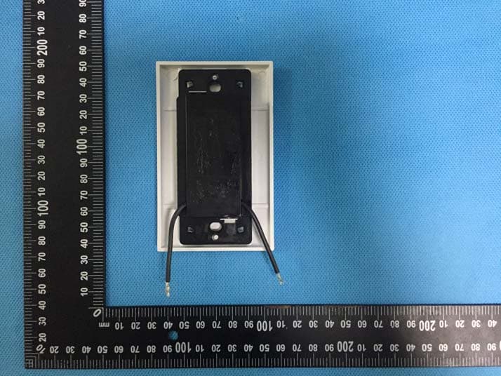
Click to zoom
Application Details
- Equipment Class
- DSC - Part 15 Security/Remote Control Transmitter
- Date of Grant
- Feb 22, 2020
- Application Purpose
- Original Equipment
- Date of Application
- Feb 22, 2020
- Equipment Note
- Transmitter
- Frequency Range
- 304.00000000 - 304.00000000
- Country
- Taiwan
Documents & Files
Document Text
Text extracted from the exhibit documents filed with the FCC. Open a document above to read the original.
Users Manual
Installation Guide net weight of fan: 11.46 lb (5.2 kg) PRINTED IN CHINA READ THESE INSTRUCTIONS AND AND SAVE THEM FOR FUTURE USE For Model: CVL100 Table of Contents: Saf et y Tips. p g. 1 Unpacking Your Fan. pg. 2 Par ts Inventory. pg. 2 Installation Preparation. pg. 3 Hanging Bracket Installation. pg. 3 Blade* Assembly. pg. 4 Fan Assembly. pgs. 4 - 6 Wiring. pgs. 6 - 7 Canopy Assembly. pg. 7 Automated Learning Process./ Activating Code. pg. 8 Testing Your Fan. pg. 9 Troubleshooting. pg. 10 Par ts Replacement. pg. 10 War ranty. p g. 10 Cavallo *sold separately WARNING DC Motor will not operate until blades are installed SAFETY TIPS. page 1 WARNING: To reduce the risk of electrical shock, turn off the electricity to the fan at the main fuse box or circuit panel before you begin the fan installation or before servicing the fan or installing accessories. 1. READ ALL INSTRUCTIONS AND SAFETY INFORMATION CAREFULLY BEFORE INSTALLING YOUR FAN AND SAVE THESE INSTRUCTIONS. CAUTION: To avoid personal injury, the use of gloves may be necessary while handling fan parts with sharp edges. 2. Make sure all electrical connections comply with Local Codes or Ordinances, the National Electrical Code, and ANSI/NFPA 70-1999. I f you are unfamiliar with electrical wiring or if the house/building wires are differ ent colors than those ref erred to in the instructions, please use a qualified electrician. 3. Make sure you have a location selected for your fan that allows clear space for the blades to rotate, and at least ten (10) feet (3.05 meters) of clearance between the floor and the fan blade tips. The fan should be mounted so that the tips of the blades are at least thirty (30) inches (76 centimeters) from walls or other upright structures. 4. The outlet box and ceiling support joist used must be securely mounted, and capable of supporting at least 35 pounds (16 kilograms). The outlet box must be supported directly by the building structure. Use only CUL (Canada) or UL (USA) listed outlet boxes marked "FOR FAN SUPPORT." WARNING: To reduce the risk of fire, electrical shock, or personal injury, mount to the outlet box marked "Acceptable for Fan Support of 15.9 kg (35 lbs.) or less," and use the mounting screws provided with the outlet box. Most outlet boxes commonly used for the support of lighting fixtures are not acceptable for fan support and may need to be replaced. Consult a qualified electrician if in doubt. WARNING: To reduce the risk of fire, electrical shock, or personal injury, wire connectors provided with this fan are designed to accept only one12 gauge house wire and two lead wires from the fan. I f your house wire is larger than 12 gauge or there is more than one house wire to connect to the corresponding fan lead wires, c onsult an electrician for the proper size wire connectors to use. 5. Electrical diagrams are for ref er ence only. 6. After installation is complete, check that all connections are absolutely secure. 7. After making electrical connections, spliced conductors should be turned upward and pushed carefully up into the outlet box. The wires should be spread apart with the grounded conductor and the equipment-grounding conductor on opposite sides of the outlet box. WARNING: To reduce the risk of electrical shock or fire, do not use this fan with any solid state speed control device or control fan speed with a full range dimmer switch. [Using a full range dimmer switch to control fan speed will cause a loud humming noise from fan.] 8. Do not insert anything between the fan blades while they are rotating. WARNING: To reduce the risk of personal injury, do not bend the blade arms during assembly or after installation. Do not insert objects into the path of the blades. WARNING: To avoid personal injury or damage to the fan and other items, be cautious when working around or cleaning the fan. 9. Do not use water or deter gents when cleaning the fan or fan blades. A dry dust cloth or lightly dampened cloth will be suitable for most cleaning. WARNING: To reduce the risk of personal injury, use only parts provided with this fan. The use of parts OTHER than those provided with this fan will v oid the warranty. WARNING: This fan MUST be installed with the safet y cable provided with the fan. F ailure to use the safet y cable provided may result in personal injury, damage to the fan or damage to other property. NOTE: The important safet y precautions and instructions appearing in the manual are not meant to cover all possible conditions and situations that may occur. I t must be understood that common sense and caution are necessary factors in the installation and operation of this fan. page 2 1. Unpacking Your Fan. Car efully open the packaging. Remove items fr om Styr of oam inserts . Remove motor housing and place on carpet or Styr of oam to avoid damage to finish. Do not discard fan carton or St yr of oam inserts should this fan need to be returned for repairs. Check against parts inventory that all parts have been included. 2. P ar ts Inventory. a. hanging bracket (pre-attached to canopy). 1 piece b. downrod and hanging ball. 1 piece c. canopy. 1 piece d. yoke cover . 1 piece e. motor housing. 1 piece f. r emote control receiver . 1 piece g h. plate. 2 pieces i. remote control cover . 2 separat e pieces j. faceplate. 3 pieces k. blades ring. 1 piece l. blade*. 3 pieces m. hardware packs IMPORTANT REMINDER: You must use the parts provided with this fan for proper installation and safety. w/ wall control g j h i 1 2 3 4 5 6 m *Blades are not included. k l a b c f d e . c ontrol panel. 2 pieces This fan can be mounted with a downrod on a regular (no-slope) or vaulted ceiling. The hanging length can be extended by purchasing a longer downrod (0.5in. /1.27cm diameter). Other installation, such as flushmount, is not available for this fan. Vaulted ceiling angle is not to exceed 19 degrees. 3. Installation Preparation. 4. Hanging Bracket Installation. page 3 ON OFF ON OFF Installation requires …
Text truncated - open the document above for the full version.
External Photos
Appendix-TP40-Photos Page 3 of 12 EUT – External View Model TP40 FCC ID: M8CTP40RF304 Appendix-TP40-Photos Page 4 of 12 Appendix-TP40-Photos Page 5 of 12
ID Label/Location Info
TP40 Label Sample and Location
Internal Photos
Appendix-TP40-Photos Page 6 of 12 EUT – Internal View Model TP40 FCC ID: M8CTP40RF304 Appendix-TP40-Photos Page 7 of 12 Appendix-TP40-Photos Page 8 of 12 ANT. Appendix-TP40-Photos Page 9 of 12 Appendix-TP40-Photos Page 10 of 12 Appendix-TP40-Photos Page 11 of 12 Appendix-TP40-Photos Page 12 of 12 ======End======
RF Exposure Info
Reference No.: WTF19S11078966W002 Page 1 of 4 Waltek Services (Shenzhen) Co.,Ltd. http://www.waltek.com.cn 1 Test Summary Test Items Test Requirement Result Maximum Permissible Exposure (Exposure of Humans to RF Fields) 1.1307(b)(1) PASS Reference No.: WTF19S11078966W002 Page 2 of 4 Waltek Services (Shenzhen) Co.,Ltd. http://www.waltek.com.cn 2 RF Exposure Test Requirement: FCC Part 1.1307 Test Mode: The EUT work in test mode(Tx). 2.1 Requirements Systems operating under the provisions of this section shall be operated in a manner that ensures that the public is not exposed to radio frequency energy levels in excess limit for maximum permissible exposure. In accordance with 47 CFR FCC Part 2 Subpart J, section 2.1091 this device has been defined as a mobile device whereby a distance of 0.2 m normally can be maintained between the user and the device. 2.2 The procedures / limit FCC Part 1.1307: (A) Limits for Occupational / Controlled Exposure Frequency Range (MHz) Electric Field Strength (E) (V/m) Magnetic Field Strength (H) (A/m) Power Density (S) (mW/ cm 2 ) Averaging Time |E| 2 ,|H| 2 or S (minutes) 0.3-3.0 614 1.63 (100)* 6 3.0-30 1842 / f 4.89 / f (900 / f)* 6 30-300 61.4 0.163 1.0 6 300-1500 F/300 6 1500-100,000 5 6 (B) Limits for General Population / Uncontrolled Exposure Frequency Range (MHz) Electric Field Strength (E) (V/m) Magnetic Field Strength (H) (A/m) Power Density (S) (mW/ cm 2 ) Averaging Time |E| 2 ,|H| 2 or S (minutes) 0.3-1.34 614 1.63 (100)* 30 1.34-30 824/f 2.19/f (180/f)* 30 30-300 27.5 0.073 0.2 30 300-1500 F/1500 30 1500-100,000 1.0 30 Note: f = frequency in MHz ; *Plane-wave equivalent power density Reference No.: WTF19S11078966W002 Page 3 of 4 Waltek Services (Shenzhen) Co.,Ltd. http://www.waltek.com.cn 2.3 MPE Calculation Method Predication of MPE limit at a given distance S = power density (in appropriate units, e.g. mW/cm 2 ) P = power input to the antenna (in appropriate units, e.g., mW). G = power gain of the antenna in the direction of interest relative to an isotropic radiator, the power gain factor, is normally numeric gain. R = distance to the center of radiation of the antenna (appropriate units, e.g., cm) From the peak EUT RF output power, the minimum mobile separation distance, d=0.2m, as well as the gain of the used antenna, the RF power density can be obtained 304MHz Mode Antenna Gain (dBi) Antenna Gain (numeric) Max.Peak Output Power (dBm) Peak Output Power (mW) Power Density (mW/cm 2 ) Limit of Power Density (mW/cm 2 ) 304 2.00 1.585 -23.09 0.00 0.000002 0.203 Note: the following is Source-based time-averaged maximum output power Calculation Frequency Source-based time-averaged maximum output power Substituted (0dBm) Source-based time- averaged maximum output power (MHz) (dBμV/m) (dBμV/m) (dBm) 304 72.11 95.2 -23.09 Reference No.: WTF19S11078966W002 Page 4 of 4 Waltek Services (Shenzhen) Co.,Ltd. http://www.waltek.com.cn 3 Photographs of test setup and EUT. Note: Please refer to appendix: Appendix-TP40-Photos ======End of Report======
Test Report
Waltek Services (Shenzhen) Co.,Ltd. http://www.waltek.com.cn Page 1 of 19 TEST REPORT Reference No. .................... : WTF19S11078966W001 FCC ID ................................ : M8CTP40RF304 Applicant ............................ : Fego Precision Industrial Co.,Ltd. Address .............................. : No947 Lin-Sen Rd. Wu Fong Shiang,Taichung Hsien,Taiwan Manufacturer .................... : Fego Precision Industrial Co.,Ltd. Address .............................. : No947 Lin-Sen Rd. Wu Fong Shiang,Taichung Hsien,Taiwan Product ............................... : Transmitter Model(s). ............................ : TP40 Standards........................... : FCC CFR47 Part 15 Section 15.231 Date of Receipt sample .... : 2019-11-14 Date of Test ....................... : 2019-11-15 to 2019-11-29 Date of Issue ...................... : 2019-12-02 Test Result ......................... : Pass Remarks: The results shown in this test report refer only to the sample(s) tested, this test report cannot be reproduced, except in full, without prior written permission of the company. The report would be invalid without specific stamp of test institute and the signatures of compiler and approver. Prepared By: Waltek Services (Shenzhen) Co., Ltd. Address: 1/F., Fukangtai Building, West Baima Road, Songgang Street, Baoan District, Shenzhen, Guangdong, China Tel :+86-755-83551033 Fax:+86-755-83552400 Compiled by: Approved by: Ford Wang / Test Engineer Philo Zhong / Manager Reference No.: WTF19S11078966W001 Page 2 of 19 Waltek Services (Shenzhen) Co.,Ltd. http://www.waltek.com.cn 2 Contents Page 1 COVER PAGE ...................................................................................................................................... 1 2 CONTENTS ............................................................................................................................................................ 2 3 REVISION HISTORY ............................................................................................................................................ 3 4 GENERAL INFORMATION .................................................................................................................................. 4 4.1 GENERAL DESCRIPTION OF E.U.T ............................................................................................................. 4 4.2 DETAILS OF E.U.T ...................................................................................................................................... 4 5 EQUIPMENT USED DURING TEST .................................................................................................................. 5 5.1 EQUIPMENTS LIST ...................................................................................................................................... 5 5.2 MEASUREMENT UNCERTAINTY ................................................................................................................... 5 5.3 SUBCONTRACTED ....................................................................................................................................... 5 6 TEST SUMMARY .................................................................................................................................................. 6 7 CONDUCTED EMISSION .................................................................................................................................... 7 7.1 E.U.T. OPERATION .................................................................................................................................... 7 7.2 EUT SETUP ................................................................................................................................................ 7 7.3 MEASUREMENT DESCRIPTION ................................................................................................................... 8 7.4 CONDUCTED EMISSION TEST RESULT ....................................................................................................... 8 8 RADIATED SPURIOUS EMISSIONS ................................................................................................................. 9 8.1 EUT OPERATION ........................................................................................................................................ 9 8.2 TEST SETUP ............................................................................................................................................. 10 8.3 SPECTRUM ANALYZER SETUP ................................................................................................................. 11 8.4 TEST PROCEDURE .................................................................................................................................... 12 8.5 SUMMARY OF TEST RESULTS .................................................................................................................. 13 9 PERIODIC OPERATION .................................................................................................................................... 14 10 20DB BANDWIDTH ............................................................................................................................................ 17 10.1 TEST PROCEDURE .................................................................................................................................... 17 10.2 TEST RESULT ........................................................................................................................................... 17 11 ANTENNA REQUIREMENT .............................................................................................................................. 18 12 PHOTOGRAPHS OF TEST SETUP AND EUT. .............................................................................................. 19 Reference No.: WTF19S11078966W001 Page 3 of 19 Waltek Services (Shenzhen) Co.,Ltd. htt…
Text truncated - open the document above for the full version.
Test Setup Photos
Appendix-TP40-Photos Page 1 of 12 Photographs –Constructional Details Transmitter Setup photo Model TP40 FCC ID: M8CTP40RF304 Photograph - Spurious Emissions Radiated Test Setup Below 30MHz Test Site 2# For 30MHz-1000MHz Test Site 2# Appendix-TP40-Photos Page 2 of 12 For Above 1GHz Test Site 1#
Contact Information
Applicant
Bruce Chang(Director)
886 4 339-1802Fax: 886 4 330-4924
Test Firm
WALTEK TESTING GROUP CO., LTD.Joy Zhou
[email protected]0769-22676998
Technical Specifications
| # | Rule Parts | Frequency Range | Power Output |
|---|---|---|---|
| 1 | 15.231 | 304 MHz - 304 MHz | - |
Other Applications from Fego Precision Industrial Co Ltd

M8C-EEC118RF433
Jul 28, 2024Remote control transmitter
Equipment Class
DSC - Part 15 Security/Remote Control Transmitter
M8C-TP36RF433-152
Apr 02, 2024Remote control transmitter
Equipment Class
DSC - Part 15 Security/Remote Control Transmitter
M8C-TP48RF433
Jun 29, 2021Remote Controller
Equipment Class
DSC - Part 15 Security/Remote Control Transmitter
M8C-TP50RF433
Jun 26, 2021Remote Controller
Equipment Class
DSC - Part 15 Security/Remote Control Transmitter
M8CRF7091BLN01
May 25, 2015Remote Control
Equipment Class
DSC - Part 15 Security/Remote Control Transmitter