M8CTP10Remote Control Transmitter
Fego Precision Industrial Co Ltd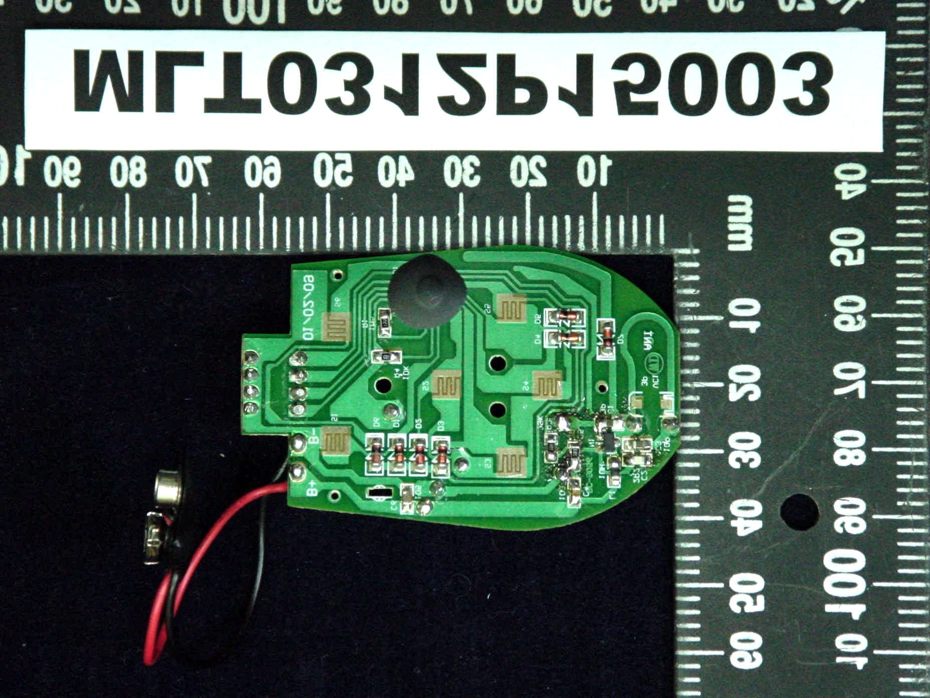
Click to zoom
Application Details
- Equipment Class
- DSC - Part 15 Security/Remote Control Transmitter
- Date of Grant
- Feb 03, 2004
- Application Purpose
- Original Equipment
- Date of Application
- Feb 03, 2004
- Equipment Note
- Remote Control Transmitter
- Frequency Range
- 316.50000000 - 316.50000000
- Country
- Taiwan
Documents & Files
Document Text
Text extracted from the exhibit documents filed with the FCC. Open a document above to read the original.
Users Manual
ThisremotecontrolhastwomodesincludeFanmodeandLightmode Fanmode 1PressHforHighspeed 2PressMforMiddlespeed 3PressLforLowspeed 4PressOfftoshutdownFanmode Lightmode 1Presson/offtocontrolLightonoroff 2PressDIMforLightdimmer Federal Communication Commission Interference Statement This equipment has been tested and found to comply with the limits for a Class B digital device, pursuant to Part 15 of the FCC Rules. These limits are designed to provide reasonable protection against harmful interference in a residential installation. This equipment generates, uses and can radiate radio frequency energy and, if not installed and used in accordance with the instructions, may cause harmful interference to radio communications. However, there is no guarantee that interference will not occur in a particular installation. If this equipment does cause harmful interference to radio or television reception, which can be determined by turning the equipment off and on, the user is encouraged to try to correct the interference by one of the following measures: • Reorient or relocate the receiving antenna. • Increase the separation between the equipment and receiver. • Connect the equipment into an outlet on a circuit different from that to which the receiver is connected. • Consult the dealer or an experienced radio/TV technician for help. This device complies with Part 15 of the FCC Rules. Operation is subject to the following two conditions: (1) This device may not cause harmful interference, and (2) this device must accept any interference received, including interference that may cause undesired operation. Caution:. Any changes or modifications not expressly approved by the party responsible for compliance could void the user's authority to operate this equipment.
Block Diagram
123456 A B C D 654321 D C B A Title NumberRevisionSize B Date:25-Dec-2003Sheet of File:C:\Client98\Sheet_1.SchDrawn By: ANTENNA MCUKEY INPUTRF OUTPUT
Cover Letter(s)
PRECISION INDUSTRIAL CO., LTD NO.192 Shun-Reen Rd. Wu-Fong Taichung Taiwan TEL:886-4-3391802 FAX:886-4-3304924 MESSERS: Max Light Technology Co.,Ltd DATE: 01/02/2004 POWER OF ATTORNEY SUBJECT: FCC APPLICATION We, the undersigned, hereby authorize Max Light Technology Co.,Ltd. To act on our behalf in all matters relating to application for equipment authorization of our model: TP10 including the signing of all documents relating to these matters. Any and all acts carried out by Max Light Technology Co.,Ltd. On our behalf shall have the same effect as acts of our own. Applicant: FEGO PRECISION INDUSTRIAL CO., LTD. By: BRUCE CHANG Signature Printed Title: DIRECTOR
Cover Letter(s)
1 Chris Harvey From:MLTLab [[email protected]] Sent:Monday, February 02, 2004 5:39 PM To:[email protected] Cc:Country Huang Subject:Fw: ??: Fw: Need Information AN04T3576 FCC ID: M8CTP10 Importance:High REPORTN.pdf (1 MB) Dear Chris, Please be informed that we have revised the report as you request on your web site. At the meanwhile, please find the attachment of revised report for your reference. Please let us know if you have any questions for the revised report. Thanks for your help. With Best Regards, Patty Huang > From: "Chris Harvey" <[email protected]> > To: <[email protected]>; "Chris Harvey" <[email protected]> > Cc: <[email protected]> > Sent: Wednesday, January 28, 2004 8:29 AM > Subject: RE: ??: Fw: Need Information AN04T3576 FCC ID: M8CTP10 > > > > Patty, yes pleased include that statement in the report along with a time > > period as measured. If there is a time period, such as the > > transmitter stops transmitting 100msec after release of button then > > add that measurement. If it stops transmitting much less than 5 > > seconds, then > please > > state that. > > > > I hope this is helpful, > > > > Chris harvey > > -----Original Message----- > > From: [email protected] [mailto:[email protected]] > > Sent: Tuesday, January 27, 2004 11:19 AM > > To: [email protected] > > Cc: [email protected] > > Subject: ??: Fw: Need Information AN04T3576 FCC ID: M8CTP10 > > > > Dear Chris, > > > > Please kindly advise that the following statement is added on the > > report if accepted. Thanks for your help. 2 > > > > > > 7.4.7. Verification of De-activation after 5 seconds > > This device stops transmitting once the activation button in > > depressed. > > > > > > Looking forward to having your advise. > > > > With Best Regards, > > Patty Huang > > > > > > > > ----- Original Message ----- > > From: "Chris Harvey" <[email protected]> > > To: <[email protected]> > > Cc: "Mike Kuo" <[email protected]> > > Sent: Friday, January 16, 2004 12:25 AM > > Subject: FW: Need Information AN04T3576 FCC ID: M8CTP10 > > > > > > > The review of the above referenced application has been performed. > > > > > > I could not locate a measurement or compliance statement of > > > compliance > > with > > > the requirements of FCC 15.231(a)(1), copied below. Please > > > provide this > > > information: > > > 15.231(a)(1): A manually operated transmitter shall employ a > > > switch that will automatically deactivate the transmitter within > > > not more than > > > 5 seconds of being released. > > > > > > The items indicated above must be submitted before processing can > continue > > > on the above referenced application. Failure to provide the > > > requested information within 30 days of the original e-mail date > > > may result in application dismissal and forfeiture of the filing > > > fee. Also, please > note > > > that partial responses increase processing time and should not be > > submitted. > > > Any questions about the content of this correspondence should be > directed > > to > > > the e-mail address listed below the name of the sender. > > > > > > Please respond directly to [email protected] > > > > > > Best regards, > > > > > > Chris Harvey > > > [email protected] > > > 443-622-3300 > > > 3 > > > > > > > > ----- ?????? ----- > > > > > > > > > > ------------------------------------------------- > > This mail sent through Seednet Webmail http://webmail.seed.net.tw > > >
ID Label/Location Info
MAX LIGHT Report Number: MLT0312P15003 Technology Lab Label Format: Label Position: This device complies with Part15 of the FCC Rules. Operation is subject to the following two conditions: (1)This device may not cause harmful interference,and (2)This device must accept any interference received ,including. Interference that may cause undesired operation. FCC ID: M8CTP10 Model No. : TP10 Rear View Equipment Lable 1.5cmX2.0cm
Internal Photos
MAX LIGHT Report Number: MLT0312P15003 Technology Lab MAX LIGHT Report Number: MLT0312P15003 Technology Lab MAX LIGHT Report Number: MLT0312P15003 Technology Lab MAX LIGHT Report Number: MLT0312P15003 Technology Lab MAX LIGHT Report Number: MLT0312P15003 Technology Lab
Operational Description
FAN REMOTE CONTROL 1 RF signal is generated by the micro controller unit (SM5028RF). It sends a series of pulse to RF circuit. 2 RF circuit uses RLC oscillator to adjust the frequency. 3 When MCU sends signal to RF circuit, the RLC generates a ASK format signal to antenna. 4 The main function keys are HI, MIDDLE, LOW, OFF, Light ON/OFF and Light dimmer. 5 There are six codes emitted by the remote controller, each key has its corresponding code.
Schematics
1234 A B C D 4321 D C B A 0 Protel Technology Inc. 4675 Stevens Creek Blvd. Suite 200 Santa Clara, CA 95051 USA 025-Dec-200317:59:15C:\Documents and Settings\hyt\\TP10 FCC.sch Title Size:Number: Date:File: Revision: SheetofTime: A4 A SNL 1 2 3 4 8 7 6 5 DP1 SW DIP-4 S4 S3 S2 S1 R1 1M5 R2 100K R3 1K C1 3P C2 1P C3 8P C4 103 L1 1UH D1 D2 VCC H L LIGHT ON/OFF M FAN () DIMMER D3 D4 D5 D6 1 1 2 2 3 3 4 4 5 5 6 6 7 7 8 8 9 9 10 10 11 11 12 12 13 13 14 14 15 15 16 16 17 17 18 18 U1 SM5028RF ANT VC 03/12/25 N1N2 N3 N4 N5 N6 N7 N8 N9 N10 N11 N18 N13 N14 N15 N16 N17 N8 N9 N10 N11 N12 N13 N14 GND GND GND GND VCC VCC N1 C3838 R4 10K VCC VCCN8 VCC S5 S6 1 B+ 1 B- C6 104 S1 S2 S3 S4 S5 S6 D8 1N4148 R1 22K
Test Report
Product : Fan remote control system for fan control appliances. Applicant : FEGO Precision IndustrialCo., Ltd. FCC ID : M8CTP10 Model : TP10 Report No. : MLT0312P15003 Issue Date : January 8, 2004 Test By Max Light Technology Co.,Ltd. Room 5, 8F, No.125, Section 3 Roosevelt Road, Taipei, Taiwan., R.O.C. Tel: 886-2-363-2447 Fax: 886-2-363-2597 T T h h e e t t e e s s t t r r e e p p o o r r t t c c o o n n s s i i s s t t s s o o f f 3 3 0 0 p p a a g g e e s s i i n n t t o o t t a a l l . . I I t t m m a a y y b b e e d d u u p p l l i i c c a a t t e e d d c c o o m m p p l l e e t t e e l l y y f f o o r r l l e e g g a a l l u u s s e e w w i i t t h h t t h h e e a a l l l l o o w w a a n n c c e e o o f f t t h h e e a a p p p p l l i i c c a a n n t t . . I I t t s s h h a a l l l l n n o o t t b b e e r r e e p p r r o o d d u u c c e e d d e e x x c c e e p p t t i i n n f f u u l l l l , , w w i i t t h h o o u u t t t t h h e e w w r r i i t t t t e e n n a a p p p p r r o o v v a a l l o o f f o o u u r r l l a a b b o o r r a a t t o o r r y y . . MAX LIGHT MEASUREMENT REPORT Page: 2/30 Report Number: MLT0312P15003 FCC ID: M8CTP10 Technology Lab Table of Contents : MAX LIGHT MEASUREMENT REPORT Page: 3/30 Report Number: MLT0312P15003 FCC ID: M8CTP10 Technology Lab CERTIFICATION We here by verify that : The test data, data evaluation, test procedures and equipment configurations shown in this report were made in accordance with the procedures given in ANSI C63.4-1992. All test were conducted by MLT (Max Light Technology Co.,Ltd) Room 5, 8F, No.125, Section 3 Roosevelt Road, Taipei, Taiwan, R.O.C Also, we attest to the accuracy of each. We further submit that the energy emitted by the sample EUT tested as described in the report is in compliance with radiated emission limit of FCC Rules Part 15 Subpart C Section 15.231. EUT : Fan remote control system for fan control appliances. Applicant : FEGO Precision IndustrialCo., Ltd. NO. 947 LIN- SEN RD., WU FONG SHIANG, TAICHUNG HSIEN, TAIWAN Manufacturer : FEGO PRECISION INDUSTRIAL CO., LTD. NO. 947 LIN- SEN RD., WU FONG SHIANG, TAICHUNG HSIEN, TAIWAN Model No : TP10 FCC ID : M8CTP10 Prepared by : Approved by : Country Huang Roger Chen MAX LIGHT MEASUREMENT REPORT Page: 4/30 Report Number: MLT0312P15003 FCC ID: M8CTP10 Technology Lab 1.1 Introduction The following measurement report is submitted on behalf of FEGO Precision IndustrialCo., Ltd. In support of an Intentional Periodic Radiator certification in accordance with Part 2 Subpart J and Part 15 Subpart A And C of the Commission’s and Regulations. 1.2 Description of EUT EUT : Fan remote control system for fan control appliances. Applicant : FEGO Precision IndustrialCo., Ltd. NO. 947 LIN- SEN RD., WU FONG SHIANG, TAICHUNG HSIEN, TAIWAN Manufacturer : FEGO PRECISION INDUSTRIAL CO., LTD. NO. 947 LIN- SEN RD., WU FONG SHIANG, TAICHUNG HSIEN, TAIWAN Model No : TP10 FCC ID : M8CTP10 Power Type : Powered by DC 9V Battery The EUT(TP10) is Remote Control of Temperature Controller. The operation frequency is 316.50 MHz. Press the button on remote transmitter, can set the H/M/L & FAN/DIM &ON/OFF button. MAX LIGHT MEASUREMENT REPORT Page: 5/30 Report Number: MLT0312P15003 FCC ID: M8CTP10 Technology Lab 1.3 Description of Support Equipment The EUT itself forms a system. No support equipment is required for its normal operation. 1.4 Configuration of System Under Test 1.5 Test Procedure All measurements contained in this report were performed according to the techniques described in Measurement procedure ANSI C63.4-1992 "Measurement of Intentional Radiators." EUT MAX LIGHT MEASUREMENT REPORT Page: 6/30 Report Number: MLT0312P15003 FCC ID: M8CTP10 Technology Lab 1.6 General Test Condition The conditions under which the EUT operates were varied to determine their effect on the equipment's emission characteristics. The final configuration of the test system and the mode of operation used during these tests was chosen as that which produced the highest emission levels. However, only those conditions which the EUT was considered likely to encounter in normal use were investigated. MAX LIGHT MEASUREMENT REPORT Page: 7/30 Report Number: MLT0312P15003 FCC ID: M8CTP10 Technology Lab The EUT operates solely by the battery. According to the rule of Section 15.207(c), the EUT exempt to the power line conducted test. MAX LIGHT MEASUREMENT REPORT Page: 8/30 Report Number: MLT0312P15003 FCC ID: M8CTP10 Technology Lab 3.1 General Configuration: Prior to open-field testing, the EUT was placed in a shielded enclosure and scanned at a close distance to determine its emission characteristics. The physical arrangement of the EUT was varied (within the scope of arrangements likely to be encountered in actual use) to determine the effect on the unit's emanations in amplitude, directivity, and frequency. The exact system configuration which produced the highest emissions was noted so it could be reproduced later during the open-field tests. This was done to ensure that the final measurements would demonstrate the worst-case interference potential of the EUT. 3.2 General Configuration: Final radiation measurements were made on a three-meter, open-field test site. The EUT system was placed on a nonconductive turntable which is 0.8 meters height, top surface 1.0 x 1.5 meter. The spectrum was examined from 250 MHz to 4 GHz in order to cover the whole spectrum below10th harmonic which could generate from the EUT. During the test,EUT was set to transmit continuously and the switch was positioned to yield the maximum duty cycle which had measured before radiated emissions test. A nonconductive material surrounded the EUT to supporting the EUT for standing on tree orthogonal planes. At each condition, the EUT was rotated 360 degrees, and the antenna was raised and lowered from one to four meters to find the maximum emission levels. Measurements were taken using both horizontal and vertical antenna polarization. The field stren…
Text truncated - open the document above for the full version.
Test Setup Photos
MAX LIGHT MEASUREMENT REPORT Page: 11/30 Report Number: MLT0312P15003 FCC ID: M8CTP10 Technology Lab 3.4 Test Configuration: Front View of The Test Configuration MAX LIGHT MEASUREMENT REPORT Page: 12/30 Report Number: MLT0312P15003 FCC ID: M8CTP10 Technology Lab Rear View of The Test Configuration
Contact Information
Applicant
Bruce Chang(Director)
886 4 339-1802Fax: 886 4 330-4924
Test Firm
Max Light Technology Co., Ltd.Jesse Tien
Technical Specifications
| # | Rule Parts | Frequency Range | Power Output |
|---|---|---|---|
| 1 | 15.231 | 316.5 MHz - 316.5 MHz | - |
Other Applications from Fego Precision Industrial Co Ltd

M8C-EEC118RF433
Jul 28, 2024Remote control transmitter
Equipment Class
DSC - Part 15 Security/Remote Control Transmitter
M8C-TP36RF433-152
Apr 02, 2024Remote control transmitter
Equipment Class
DSC - Part 15 Security/Remote Control Transmitter
M8C-TP48RF433
Jun 29, 2021Remote Controller
Equipment Class
DSC - Part 15 Security/Remote Control Transmitter
M8C-TP50RF433
Jun 26, 2021Remote Controller
Equipment Class
DSC - Part 15 Security/Remote Control Transmitter
M8CTP40RF304
Feb 22, 2020Transmitter
Equipment Class
DSC - Part 15 Security/Remote Control Transmitter