M8CTR110BLRF Transmiter
Fego Precision Industrial Co Ltd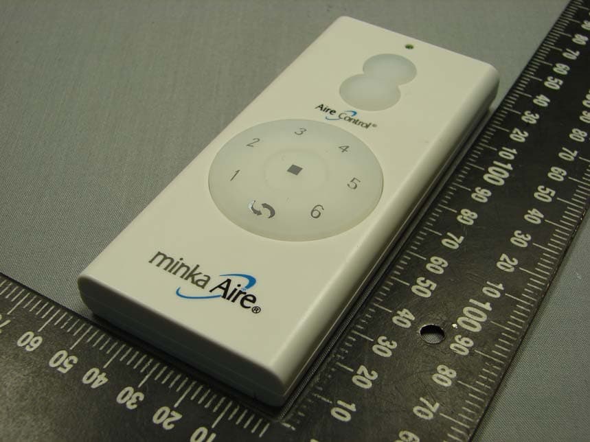
Click to zoom
Application Details
- Equipment Class
- DSC - Part 15 Security/Remote Control Transmitter
- Date of Grant
- Apr 16, 2013
- Application Purpose
- Original Equipment
- Date of Application
- Apr 15, 2013
- Equipment Note
- RF Transmiter
- Frequency Range
- 433.90000000 - 433.90000000
- Country
- Taiwan
Documents & Files
Document Text
Text extracted from the exhibit documents filed with the FCC. Open a document above to read the original.
Users Manual
Manual design and all elements of manual design are protected by U.S. Fede This product is protected by United States Federal and/or State Law, including Patent, Trademark and/or Copyright laws. ral and/or State Law, including Patent, Trademark and/or Copyright Laws. warranty is for one (1) year from the date of purchase from an authorized Minka-Aire dealer. This warranty is only valid to the original purchaser or user against all defects in material and workmanship (light bulbs excluded) for one (1) full year. Additionally, Minka-Aire warrants the motor only for the lifetime of the Minka Aire ceiling fan (excluding wall controls and electrical components), to the original purchaser or user. The warranty is voided with the use of any non- Minka-Aire electrical devices, E.g., wall controls or electrical dimmer switches, etc... The warranty is void once the original purchaser or user ceases to own the fan or the fan is moved from its original point of installation. The warranty is void with the use of any hanger bracket (non-Minka Aire or non-fan specific) other than the hanger bracket supplied & installed with this specific fan. To obtain the name of the Minka-Aire authorized dealer nearest you call the Minka-Aire customer care department at 1-800-307-3267, or contact Minka-Aire through www.minkagroup.net and write to: “Ask Mr. Minka” to answer any questions or if you require assista nce. To obtain warranty servic during the warranty period, the purchaser should return the fan with the sales receipt to the original place of purchase. The authorized Minka-Aire dealer, at its sole discretion, will either repair or replace the fan after verifying the legitimacy of the warranty claim. Replacement is subject to availability of the same model. If the model is unavailable it will be replaced by one of equ al value. This is a limited warranty; the original purchaser or user is responsible for the cost of removal and reinstallation of repaired or replacement product. ® ® ® ® Date Purchased Store Purchased Model Number Serial Number F853 Warranty Service Information CONTENTS 1151W. Bradford Court, Corona CA 92882 For Customer Assistance Call: 1-800-307-3267 SAFETY FIRST1 PACKAGE CONTENTS2 BEG IN INSTALLATION3 HANG ING THE FAN4 ELECTRI CAL CONNECTIONS5 ATTACHING THE FAN BLADES7 ATTACHING THE BOTTOM CAP AND RING 8 OPER ATING THE REMOTE CONTROL/WALL CONTROL 9 MAINTENANCE10 TROUBLESHO OTING11 FINISHING THE INSTALLATION6 SPECIFICATIONS 12 1. Before you begin installing the fan, shut power off at the circuit breaker of the fuse box. 2. Be cautious! Read all instructions and safety information before installing your new fan. Review accompanying assembly diagrams. 3. Make sure that all electrical connections comply with local codes, ordinances, or National Electrical Codes. Hire a qualified electrician or consult a do-it-yourself wiring handbook if you are unfamiliar with installing electrical wiring. 4. Make sure the installation site you choose allows the fan blades to rotate without any obstructions. Allow a minimum clearance of 7 feet from the floor and 18 inches from the tip of the blades to the wall. 5. NOTE: THIS CEILING FAN EXCEEDS THE MAXIMUM WEIGHT SPECIFIED BY UL FOR HANGING FROM A STANDARD OUTLET BOX. SPECIAL REINFORCEMENT OF THE CEILING IS REQUIRED FOR INSTALLATION. 6. CAUTION: Use the wood screws provided for fan installation. The wood screws must go through the outlet box via the knock outs and secured directly to the building joist. 7. After you install the fan, make sure that all mounting components are secured to prevent the fan from falling. 8. Do not insert anything into the fan blades while the fan is operating. 9. Turn the fan off and wait for the blades to stop completely before cleaning or performing any maintenance. 1 SAFETY FIRST WARNING TO REDUCE THE RISK OF FIRE, ELECTRIC SHOCK OR OTHER PERSONAL INJURY. MOUNT FAN DIRECTLY TO THE BUILDING JOIST USING TH E WOOD SCREWS AND WASHERS PROVIDED WITH THE FAN. THE WOOD SCREWS MUST GO THROUGH THE OUTLET BOX VIA THE KNOCK OUTS. CONSULT A QUALIFIED ELECTRICIAN IF IN DOUBT. TO REDUCE THE RISK OF PERSONAL INJURY, DO NOT BEND THE BLADE HOLDERS WHILE INSTALLING, BALANCING THE BLADES, O R CLEANING THE FAN. DO NOT INSERT FOREIGN OBJECTS BETWEEN ROTATING FAN BLADES. TO REDUCE THE RISK OF FIRE OR ELECTRIC SHOCK, DO NOT USE THIS FAN WITH ANY SOLID-STATE SPEED CONTROL DEVICE. TO REDUCE THE RISK OF FIRE OR ELECTRONIC SHOCK, THIS FAN ONLY CAN USE THIS FAN ONLY CAN USE 120DC-3-1 RECEIVER AND RC500 REMOTE CONTROL ONLY. NOTE:The important safeguards and instructions appearing in this manual are not meant to cover all possible conditions and situations that may occur. It must be understood that common sense, caution and care are factors which can not be built into this product. These factors must be supplied by the person (s) installing, caring for and operating the unit. NOTE: READ AND SAVE ALL INSTRUCTIONS! 1. Fan motor/housing ass'y 2.Canopy 3.Fan blade 4.Coupling cover 5.Canopy cover 6.Hanger bracket 7.Bottom cap 9.Standard 6"downrod assembly 8.Ring 10. Minimun 3-1/2" length downrod (for close to ceiling mounting only) 11. Remote control 2 PACKAGE CONTENTS A. Blade attachment hardware: #10-24x12mm hex screw (7pcs) B. Mounting Hardware: #8-32x38mm screw(2pcs) #10x38mm wood screw (2pcs) 3/16"(Ø5.2x8.4x1.0mm) spring washer(2pcs) Ø5x14x1mm flat washer (2pcs) 5/32"(Ø4.4x9.4x0.5-1.0mm -10 tooth) wash(2 pcs) C. #8-32x7mm texture hex screws (7pcs) D. M3 L hex wrentch(1pcs) E. Wire nut(3pcs) G. Balance kit H. Glove I. Clean cloth BEGIN INSTALLATION MOUNTING OPTIONS If there isn't an existing mounting box,then read the following instructions.Shut the power off at the circuit breaker or fuse box. NOTE: THIS CEILING FAN EXCEEDS THE MAXIMUM WEIGHT SPECIFIED BY UL FOR HANGING FROM A STANDARD OUTLET BOX. SPECIAL REINFORCEMENT OF THE CEILING IS REQUIRED FOR INSTALLATION. Secure the ceiling fan's hanging bracket directly from the building structure via the outlet box. F…
Text truncated - open the document above for the full version.
Users Manual
Black(hot)Green or bare copper (ground) Black ("ac in l") Ground(green) (connect toground wire on hanger bracke if no house ground wire exists.) White (neutral) White ("ac in n") Fig.11 Step 2. If your outlet box has a GROUND wire (Green or Bare Copper) connect this wire to the Hanger Ball and Hanger Bracket Ground wires. If your outlet box does not have a Ground Wire, then connect the Hanger Ball and Hanger Bracket Ground Wires together. Secure wire connection with the plastic wire nut provided. (Fig. 11) After all splices are made, check to make sure there are no loose strands. As an additional precaution we suggest to secure the plastic wire connectors to the wires with electrical tape. NOTICE: This device complies with Part 15 of FCC rules. Operation is subject to the following two conditions: (1) This device may not cause harmful interference, and (2) this device must accept any interference received, including interference that may cause undesired operation. WARNING: Changes or modifications not expressly approved by the party responsible for compliance could viod the user’s authority to operate the equipment. AVIS : Cet appareil est conforme à la section 15 des règlements de la FCC. Opération est sujette aux deux conditions suivantes: (1) cet appareil ne doit pas émettre de brouillage nuisible, et (2) cet appareil doit accepter toute interférence reçue, y compris les interférences pouvant entraîner un fonctionnement indésirable. AVERTISSEMENT : Les changements ou modifications non expressément approuvés par la partie responsable de la conformité pourraient viod autorisation de l'utilisateur à faire fonctionner l'équipement. Step 1. Remove 1 of the 2 screws from the bottom of the hanger bracket and loosen the other one half a turn from the screw head. (Fig. 12) Step 2. Slide the canopy up towards the hanger bracket and place the key hole on the canopy over the screw on the hanger bracket, turn canopy until it locks in place at the narrow section of the key holes. (Fig. 13) Step 3. Align the circular hole on canopy with the remaining hole on the hanger bracket, secure by tightening the two set screws. (Fig. 14) Step 4. Twist the canopy hole cap to fit it on canopy. FINISHING THE INSTALLATION Fig.12Fig.13Fig.14 6 Attach the fan blade to the blade holder on motor using the hex wrench provided in the screw pack. (Fig. 15) ATTACHING THE FAN BLADES Fig.15 Blade Holder Receiver And Box Hex Wrentch Screw Blade 7 Align the holes on the bottom cap and the holes on the ring to the holes on the blades and using the hex wrench and hex screws provided secure both to the fan blades. (Fig.16) ATTACHING THE BOTTOM CAP AND RING Fig. 16 Blade Screw Ring Hex Wrentch Bottom Cap 8 9 NOTE: THIS FAN HAS BEEN PRECISION BALANCED AT THE FACTORY AND WILL NOT NEED TO BE BALANCED AGAIN. cold 3 4 within 3 Minutes of turning the fans AC power on. the lowest Speed setting. The fan will continue to spin until the "STOP" button has been pressed. The DC motor has a built in safety against obstruction during operation, if the fan motor senses a obstruction it will get locked and will not rotate until the power has been disconnected for 10 seconds. The "D" that appears on the back of the remote control next to the frequency dip switches is used when using CFL bulbs only. Leaving the dip switch in the "D" setting will allow for dimming capability. In the "ON" position it will disable the Dimming function. Fig 17 Fig 18 SUMMER OPERATION WINTER OPERATION Speed settings for warm or cold weather depend on factors such as room size, ceiling height and number of fans. NOTE: To change the direction of the rotation of the blades the fan must be in operation mode. Warm Weather (forward) A DOWNWARD airflow creates a cooling effect as shown in Figure 17. This allows you to set your air conditioner on a warmer setting without affecting your comfort. Cool Weather (Reverse) An UPWARD airflow moves warmer air off the ceiling area as shown in Figure 18.This allows you to set your heating unit on a cooler setting without affecting your comfort. Here are some suggestions to help you maintain your fan. 1. Because of the fan's matural novement,some connections may become loose. Check the support connections,brackets, and blade attachments twice a year. Make sure they are secure (It is not necessary to remove fan from ceiling. ) 2. Clean your fan periodically to help maintain its new appearance over the years. Do not use water when cleaning. This could damage the motor,or the wood,or possibly cause an electrical shock. 3. Use only a soft brush or lint-free cloth to avoid scratching the finish. The plating is sealed with a lacquer to minimize discoloration or tarnishing. 4. You can apply a light coat of furniture polish to the wood for additional protection and enhanced beauty. Cover small scratches with a light application of shoe polish. 5. There is no need to oil your fan. The motor has permanently lubricated bearings. 10 CARE OF YOUR FAN WARNING MAKE SURE THE POWER IS OFF AT THE ELECTRICAL PANEL BOX BEFORE YOU ATTEMPT ANY REPAIRS. REFER TO THE SECTION, "MAKING ELECTRICAL CONNECTIONS". SYMPTOM Fan Wobble SOLUTION 1.NOTE: All blade sets are grouped by weight. Because wood and plastic blades vary in density, the fan may wobble even though blades are matched. 2.Make sure outlet box is secured to building structure, if necessary use the wood screws provided to further secure outlet box to joist. 3 . Make sure hanger bracket is secure to the outlet box, screws are tight. SYMPTOM Fan will not start SOLUTION SYMPTOM Fan sound noisy SOLUTION 1. Allow a 24-hour "break in" period. Most noises associated with a new fan will go away during this time. 2. Make sure all blade attachment screws are tight. 3. Make sure outlet box is secured to building structure, if necessary use the wood screws provided to further secure outlet box to joist. 4. Make sure hanger bracket is secure to the outlet box, screws are tight. TROUBLESHOOTING 11 1.Check to make sure…
Text truncated - open the document above for the full version.
Cover Letter(s)
電話 886-4-23391802 傳真 886-4-23399374 統一編號 84430243 協記精密工業股份有限公司 FEGO Precision Industrial Co., Ltd. 台中縣霧峰鄉 413 林森路 947 號 947 Lin-Sen Rd. Wu-Fong Tai-Chung 413 Taiwan ROC Date: 28 March, 2013 Federal Communications Commission Office of Engineering and Technology Equipment Authorization Division 7345 Oakland Mills Road Columbia, Maryland 21046 Subject: Permanent Confidentiality request for FCC ID: M8CTR110BL To Whom It May Concern, Pursuant to sections 0.457 and 0.459 of CFR 47, the applicant requests permanent confidential treatment of the following information accompanying this application: Block Diagrams Schematics Operational Descriptions The above materials contain trade secrets and proprietary information not customarily released to the public. The public disclosure of these matters might be harmful to the applicant and provide unjustified benefits to its competitors. Sincerely, Bruce Chang / President _____________________________ (Signature)
Cover Letter(s)
電話 886-4-23391802 傳真 886-4-23399374 統一編號 84430243 協記精密工業股份有限公司 FEGO Precision Industrial Co., Ltd. 台中縣霧峰鄉 413 林森路 947 號 947 Lin-Sen Rd. Wu-Fong Tai-Chung 413 Taiwan ROC AGENCY AUTHORIZATION LETTER To whom it may concern: We, the undersigned FEGO Precision Industrial Co., Ltd , hereby authorize Max Light Technology Co. Ltd. (MLT) of Taiwan to act on our behalf in all matters relating to all processes required in the FCC Part 15 approval and any communication needed with the national authority. Any and all acts carried out by MLT on our behalf shall have the same effects as acts of our own. For questions regarding the authorization, please contact us. Thank you! Sincerely yours, _____________________________________ (Signature) Original written signature of authorized signer: Bruce Chang / President Printed name of authorized signer / Title Date: March 28, 2013
External Photos
Report Number: MLT1303P15001 Photograph of EUT
ID Label/Location Info
Report Number: MLT1303P15001 Label Format: Label Position: Equipment Label 19mmX29mm Rear View This device complies with Part15 of the FCC Rules. Operation is subject to the following two conditions: (1) This device may not cause harmful interference, and (2) This device must accept any interference received , including Interference that may cause undesired operation. Trade Name : FEGO Model No. : TR110BL FCC ID: M8CTR110BL
Internal Photos
Report Number: MLT1303P15001 Report Number: MLT1303P15001
Test Report
Page: 1 / 28 Report Number: MLT1303P15001 (FCC : Part 15 Subpart C / ANSI C63.4-2003) Product : RF Transmitter Trade Name : FEGO Model No. : TR110BL Applicant : FEGO Precision Industrial Co.,Ltd Applicant Address : 947 Lin-Sen Rd.Wu-Fong Tai-Chung 413 Taiwan ROC Page: 2 / 28 Report Number: MLT1303P15001 Report Number MLT1303P15001 Applicant FEGO Precision Industrial Co.,Ltd Product RF Transmitter Sample Received Date 2013/3/15 Sample Tested Date 2013/3/15 ~2013/3/26 Report Prepared By Jesse Tien Signature Date Prepared 2013/4/8 Report Authorized By Roger Chen Signature Date Authorized 2013/4/8 Test By Max Light Technology Co., Ltd. Room 5, 8F, No.125, Section 3 Roosevelt Road, Taipei, Taiwan., R.O.C. Office : Tel: 886-2-2363-2447 Fax: 886-2-2363-2597 Lab. : Tel: 886-2-2663-3486 Fax: 886-2-2663-3582 It may be duplicated completely for legal use with the allowance of the applicant. It shall not be reproduced except in full, without the written approval of our laboratory. Page: 3 / 28 Report Number: MLT1303P15001 Table of Contents : History of Test Report .............................................................................................................. 4 1. General......................................................................................................................6 2. Conducted Emissions Requirements......................................................................... 8 3. Radiated Emissions Requirements............................................................................ 9 4. Transmitter Bandwidth Measurements.................................................................... 19 5. Transmitter Duty Cycle Measurements................................................................... 21 6. Verification of De-activation after 5 seconds ...........................................................25 Appendix I - EUT Test Setup ................................................................................................. 27 Appendix II – Brand / Trade Name & Model No. Multiple Listee ............................................ 28 Page: 4 / 28 Report Number: MLT1303P15001 History of Test Report Original Report Issue Date: 2013/4/8 ■ No additional attachment □ additional attachments were issued as in the following record: Attachment No. Issue Date Description MLT1303P15001 2013/4/8 Original report Page: 5 / 28 Report Number: MLT1303P15001 CERTIFICATION We here by verify that : The test data, data evaluation, test procedures and equipment configurations shown in this report were made in accordance with the procedures given in ANSI C63.4-2003. All test were conducted by MLT(Max Light Technology Co., Ltd) Room 5, 8F, No.125, Section 3 Roosevelt Road, Taipei, Taiwan, R.O.C Also, we attest to the accuracy of each. We further submit that the energy emitted by the sample EUT tested as described in the report is in compliance with radiated emission limit of FCC Rules Part 15 Subpart C Section 15.231. Applicant Name FEGO Precision Industrial Co.,Ltd Applicant Address 947 Lin-Sen Rd.Wu-Fong Tai-Chung 413 Taiwan ROC Manufacturer Name FEGO Precision Industrial Co.,Ltd Manufacturer Address 947 Lin-Sen Rd.Wu-Fong Tai-Chung 413 Taiwan ROC Equipment RF Transmitter Model No TR110BL FCC ID M8CTR110BL Report Prepared By Jesse Tien Signature Report Authorized By Roger Chen Signature Page: 6 / 28 Report Number: MLT1303P15001 1. General 1.1 Introduction The following measurement report is submitted on behalf of FEGO Precision Industrial Co.,Ltd In support of an Intentional Periodic Radiator certification in accordance with Part 2 Subpart J and Part 15 Subpart A and C of the Commission’s and Regulations. 1.2 Customer Details Applicant Name FEGO Precision Industrial Co.,Ltd Applicant Address 947 Lin-Sen Rd.Wu-Fong Tai-Chung 413 Taiwan ROC Manufacturer Name FEGO Precision Industrial Co.,Ltd Manufacturer Address 947 Lin-Sen Rd.Wu-Fong Tai-Chung 413 Taiwan ROC 1.3 Technical data of EUT Equipment RF Transmitter Model No TR110BL FCC ID M8CTR110BL Power Type Powered by 12V Battery (23AE) The EUT is a remote transmitter. The operation frequency is 433.9MHz. 1.4 Description of Support Equipment The EUT itself forms a system. No support equipment is required for its normal operation. Page: 7 / 28 Report Number: MLT1303P15001 1.5 Configuration of System Under Test 1.6 Test Procedure All measurements contained in this report were performed according to the techniques described in Measurement procedure ANSI C63.4: 2003 "Measurement of Intentional Radiators." 1.7 General Test Condition The conditions under which the EUT operates were varied to determine their effect on the equipment's emission characteristics. The final configuration of the test system and the mode of operation used during these tests was chosen as that which produced the highest emission levels. However, only those conditions which the EUT was considered likely to encounter in normal use were investigated. The EUT is a manually activated device and it will follow the 15.231(b) requirement. EUT Page: 8 / 28 Report Number: MLT1303P15001 2. Conducted Emissions Requirements The EUT operates solely by the battery. According to the rule of Section 15.207(c), the EUT exempt to the power line conducted test. Page: 9 / 28 Report Number: MLT1303P15001 3. Radiated Emissions Requirements 3.1 General Configuration: Prior to open-field testing, the EUT was placed in a shielded enclosure and scanned at a close distance to determine its emission characteristics. The physical arrangement of the EUT was varied (within the scope of arrangements likely to be encountered in actual use) to determine the effect on the unit's emanations in amplitude, directivity, and frequency. The exact system configuration which produced the highest emissions was noted so it could be reproduced later during the open-field tests. This was done to ensure that the final measurements would demonstrate the worst-case interference potential of the EUT. 3.2 General C…
Text truncated - open the document above for the full version.
Test Setup Photos
Report Number: MLT1303P15001 Photograph of Radiated Measurement Front View of The Test Configuration Rear View of The Test Configuration Report Number: MLT1303P15001
Contact Information
Applicant
Bruce Chang(Director)
886 4 339-1802Fax: 886 4 330-4924
Technical Contact
Max Light Technology Co., Ltd.Jesse Tien
[email protected]886-2-2663-3486
8F-5, No.125, Sec 3, Roosevelt Rd. · Taipei City · Taiwan
Test Firm
Max Light Technology Co., Ltd.Jesse Tien
Technical Specifications
| # | Rule Parts | Frequency Range | Power Output |
|---|---|---|---|
| 1 | 15.231 | 433.9 MHz - 433.9 MHz | - |
Other Applications from Fego Precision Industrial Co Ltd

M8C-EEC118RF433
Jul 28, 2024Remote control transmitter
Equipment Class
DSC - Part 15 Security/Remote Control Transmitter
M8C-TP36RF433-152
Apr 02, 2024Remote control transmitter
Equipment Class
DSC - Part 15 Security/Remote Control Transmitter
M8C-TP48RF433
Jun 29, 2021Remote Controller
Equipment Class
DSC - Part 15 Security/Remote Control Transmitter
M8C-TP50RF433
Jun 26, 2021Remote Controller
Equipment Class
DSC - Part 15 Security/Remote Control Transmitter
M8CTP40RF304
Feb 22, 2020Transmitter
Equipment Class
DSC - Part 15 Security/Remote Control Transmitter