MHI-CAWCB5005.15 - 5.35 GHz UNII CardBusTransceiver model CAWC
Card Access Inc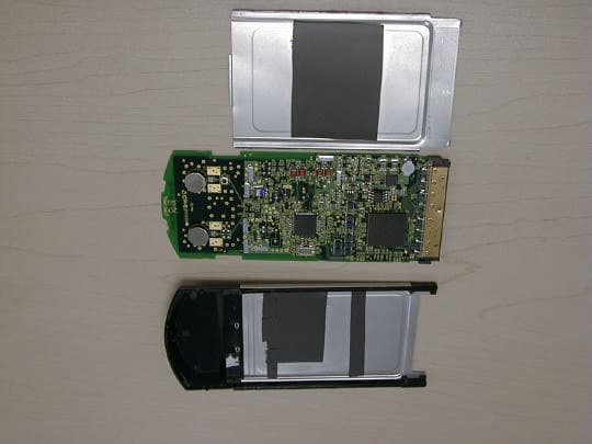
Click to zoom
Application Details
- Equipment Class
- NII - Unlicensed National Information Infrastructure TX
- Date of Grant
- Oct 14, 2001
- Application Purpose
- Original Equipment
- Date of Application
- Aug 02, 2001
- Equipment Note
- 5.15 - 5.35 GHz UNII CardBusTransceiver model CAWC
- Frequency Range
- 5180.00000000 - 5320.00000000
- Company
- Card Access Inc
- Country
- United States
Documents & Files
Document Text
Text extracted from the exhibit documents filed with the FCC. Open a document above to read the original.
Users Manual
C C A A W W C C B B 5 5 0 0 0 0 P P C C C C a a r r d d Quick Start Guide http://www.insertwebaddresshere.com/ Part No. 00-0000-000 Published July 2001 Card Access Corporation 0000 Street Address City, State Zip Copyright © 2001. All rights reserved. No part of this documentation may be reproduced in any form or by any means or used to make any derivative work (such as translation, transformation, or adaptation) without the written permission of Card Access Corporation. Card Access Corporation reserves the right to update and otherwise change the content of this document without being obligated to provide notification of revision. Card Access Corporation provides this documentation without term, warranty, or condition of any kind, either expressed or implied, including (but not limited to) the implied terms, warranties, or conditions of merchantability, satisfactory quality, and appropriateness for a particular purpose. Card Access Corporation may improve or otherwise change the product(s) and/or the program(s) described in this documentation at any time. The product described in this documentation includes a license agreement as a separate document in a directory file named NAME.TXT. If you are unable to locate a copy, please contact Card Access Corporation and a copy will be provided to you. United States Government Legend If you are the United States government agency, then this documentation and the software described herein are provided to you on the following conditions: Insert text here. All technical data.... Unless otherwise indicated, Card Access Corporation registered trademarks are registered in the United States and may or may not be registered in other countries. Card Access Corporation, the Card Access Corporation logo, and Product Name are registered trademarks of Card Access Corporation. Microsoft, Windows, and Windows NT are registered trademarks of Microsoft Corporation. All other company and product names may be trademarks of the respective companies with which they are associated. Export Restrictions: Insert text here. – 1 – X Quick Start Guide This Quick Start Guide is intended for users familiar with PC Card and driver installation for Windows 98, Windows ME, and Windows 2000. Refer to "Installing the Documentation" on page four of this Quick Start Guide for information on setting up the online documentation. Installation for Windows 98, ME, and Windows 2000 Before installing the driver, you will need a copy of the operating system installation media, usually a CD supplied with your computer or operating system. On Windows 98 systems, the installation files are sometimes archived on the hard disk in C:\WINDOWS\OPTIONS\CABS. On Windows 2000 systems, you may be prompted to load operating system files from the Windows 2000 installation disk. You will also need the End User Utilities CD supplied with your Card Access PC Card. the Setup program installs configuration utilities in the Network application in the Control Panel. Run Setup from the End User Utilities CD 1 1 . . Turn on your computer. 2 2 . . Put the End User Utilities CD in the CD-ROM drive. The setup program should start automatically. If it does not start, you can run it manually by selecting Run from the Start menu and running SETUP.EXE from the CD-ROM Drive. 3 3 . . On the Card Access WLAN Menu screen, select Installation for Windows. 4 4 . . Select Adapter Installation Instructions. Follow the instructions as they appear on the screen. 5 5 . . When prompted, insert the Card Access PC Card into the PC Card slot (Figure 1). Align the card properly before putting it in the slot. Insert the card firmly without forcing until it seats snugly. CAUTION: Forcing a misaligned card into the slot can damage the computer or the card. The driver-installation procedure guides you through the steps standard for your operating system. If you are unfamiliar with driver-installation procedures, refer to the Network Interface Card User Guide for details. You will be asked to supply CDs or directory-path information for the End User Utilities CD and your operation-system software. The setup program will install and open the Network application in the Control Panel as part of the driver-installation process. 6 6 . . Enter the name of the Wireless LAN Service Area of the wireless network to which your computer will connect. The name you enter here must be identical to the name assigned to the access point. Capitalization, characters, and spacing must match exactly. – 2 – i X NOTE: If the access point you wish to associate with is set for encryption, you must also enable encryption on the wireless client. Click Advanced to go to screens where you can enable and configure encryption. You must set the wireless client for the same encryption algorithm and Shared Key values as the access point it will associate with. Refer to the Network Interface Card User Guide for more details about configuring encryption. 7 7 . . Dave the configuration settings and exit by clicking OK. 8 8 . . Restart your computer. 9 9 . . Make sure that the network protocol parameters, including the IP address, gateway, and subnet mask, are set correctly for your computer. 1 1 0 0 . . When the system reboots, restart the setup program and install any other required components. Card Access Corporation recommends that you install the wireless LAN applications so you can access the utilities described in the Network Interface Card User Guide. 1 1 1 1 . . Restart your computer. Orienting the Antenna The PC Card antenna is attached to the end of the PC Card. Caution: Do not attempt to remove the antenna on the PC Card. If you pull on or bend the antenna, you might break the antenna and cause permanent damage to the card. Follow these guidelines for optimum use of the antenna: • Keep the area around the antenna clear from materials that could block radio transmission, such as metal objects, electronic devices, and cordless telephones. • If necessary, move your not…
Text truncated - open the document above for the full version.
External Photos
Inside View of Covers and PCB: (Echo Sorb Material Located on Top and Bottom Covers) Top Cover Assembled: Completed Assembly Backside View
ID Label/Location Info
CAWCB500 Label Dimensions and Placement Top Label: Label Dimensions = 2.48 x 1.55 in. Label Material = .002in TC/249 White Mylar. Label Adhesive = Permanent Adhesive. Label Placement: Both top and bottom labels must be centered in the recessed area of the top and bottom metal covers. Bottom Label: (Same Dimension as top label) 2.48 in 1.55 in
ID Label/Location Info
Model CAWCB500 Card Access TM 802.11a CardBus Card This device complies with Part 15 of the FCC Rules and Canada RSS-210. Operation is subject to the following conditions: (1) This device may not cause harmful interference, and (2) this device must accept any interference received, including interference that may cause undesired operation. This Class B digital apparatus complies with Canada ICES-003. FCC ID: MHI-CAWCB500 CANADA: REV: MAC: ©Copyright Card Access, Inc. 2001
RF Exposure Info
SAR COMPLIANCE TESTING OF CARD ACCESS MODEL MHI-CAWCB500 5.15 TO 5.35 GHz CARDBUS CARD INSERTED INTO A LAPTOP COMPUTER July 18, 2001 Submitted to: Mr. Nathan Mueller Design Engineer Card Access 71 North 490 West American Fork, UT 84003 Submitted by: Om P. Gandhi Professor of Electrical Engineering University of Utah 50 S Central Campus Dr., Rm. 3280 Salt Lake City, UT 84112-9206 SAR COMPLIANCE TESTING OF CARD ACCESS MODEL MHI-CAWCB500 5.15 TO 5.35 GHz CARDBUS CARD INSERTED INTO A LAPTOP COMPUTER I. Introduction The U.S. Federal Communications Commission (FCC) has adopted limits of human exposure to RF emissions from mobile and portable devices that are regulated by the FCC [1]. The FCC has also issued Supplement C (Edition 97-01) to OET Bulletin 65 [2] and a more recent version of the same [3] defining both the measurement and the computational procedures that should be followed for evaluating compliance of mobile and portable devices with FCC limits for human exposure to radiofrequency emissions. We have used both the measurement and computational procedures for SAR compliance testing of the Card Access CardBus card (FCC ID: MHI-CAWCB500) inserted into a laptop computer. A photograph of the unit with the CardBus card inserted into the laptop computer is given in Fig. 1. A picture of the Model CAWCB500 CardBus card placed on the laptop is given in Fig. 2. For spatial diversity, the CardBus card uses two 5 GHz Side Stem Antennas each of geometry and dimensions given in Fig. 3. The antenna feed of width 1.75 mm and length 1.8 mm shown in Fig. 3 is mounted on a substrate of thickness 10 mils (0.25 mm) and dielectric constant 4.25. The two antennas are placed with a center-to-center spacing of 24.23 mm over a ground plane of width 43 mm and approximate length 45 mm. At any given time, only one of the two antennas is working either for the transmission or the reception mode. The Card Access Model CAWCB500 CardBus card operates with a transmit power to up to 16 dBm (40 mW). Since the wireless PC may possibly be placed on a user's lap where the RF antennas would be the closest to the body, a planar phantom model was used both for SAR calculations as well as for SAR measurements. 2 II. Computation of SAR Distributions The Finite Difference Time-Domain Method One of the most successful and versatile methods for SAR calculations is the finite-difference time-domain (FDTD) method. This method was first proposed by Yee [4] and later developed by Taflove and colleagues [5-7], Holland [8], and Kunz and Lee [9]. This method has been extensively used for calculations of the distributions of electromagnetic (EM) fields and SARs in anatomically-based models of the human body for whole-body or partial-body exposures due to far-field or near-field irradiation conditions [10, 11]. In this method, the time-dependent Maxwell's curl equations ∇×E=-μ ∂H ∂t ,∇×H=σE+ε ∂E ∂t (1) are implemented for a lattice of sub volumes or "cells" that may be cubical or parallelepiped with different dimensions δ x , δ y , and δ z in x-, y-, or z-directions, respectively. The components of E and H are positioned about each of the cells as shown in Fig. 4 and calculated alternately with half-time steps where the time step δt = δ/2c where δ is the smallest of the dimensions used for each of the cells and c is the maximum phase velocity of the fields in the modeled space. Since some of the modeled volume is air, c corresponds to the velocity of EM waves in air. The details of the method are given in several of the above referenced publications [4-9] and will, therefore, not be repeated here. In the FDTD method, it is necessary to represent not only the scatterer/absorber such as the human body or a part thereof, but also any near-field sources/s such as the Side Stem Antenna of Fig. 3 mounted into a laptop computer. Since the SAR distribution is critically dependent on the antenna geometry and its placement vis à vis the lossy planar model simulant of the human lap, this region was modeled with an FDTD cell size of 0.6 × 0.6 × 0.6 mm. This choice of the cell dimensions allowed a proper 3 representation of the stem antenna height (3.6 mm), its width (1.75 or nearly 1.8 mm), the top loading circular hat (diameter 8.4 mm) and the antenna feed of width 1.75 or 1.8 mm and length 1.8 mm), the ground plane of dimensions (42 × 74.4 mm) and the separation between the bottom of the ground plane to the top of the lap-simulant model of 1.08 cm (18 cells). For SAR calculations, we have assumed a planar muscle-simulant lossy phantom at a distance of 1.08 cm below the CardBus card ground plane to account for a part of the thickness of the PC keyboard. For this planar model of dimensions 13.8 × 10.8 × 5.4 cm modeled by 230 × 180 × 90 cells (of dimension 0.6 mm), we have used muscle-simulant dielectric properties of ε r = 49.22 and conductivity σ = 4.32 S/m taken from the FCC website [www.fcc.gov/fcc-bin/dielec.sh]. Similar to the FDTD cell size used for modeling of the antenna, this planar tissue-simulant is also modeled by a cell size of 0.6 mm. A graphical representation of the SAR distributions calculated for the surface layer and for three additional layers at depths of 3, 6, and 9 mm are shown in Fig. 5, respectively. For all of these calculations, the antenna excited for a total radiated power of 16 dBm (40 mW) is assumed to be in the upper right hand corner which explains the high SARs for the phantom underneath. The calculated power absorbed by the entire phantom is 8.20 mW (20.5% of the conducted power) and the peak 1-g SAR is 0.176 W/kg. For SAR calculations, we have also used a second tissue-simulant phantom which is a proper representation of the rectangular box phantom used for experimental SAR measurements (see Fig. 7). This box phantom described in detail in Section V uses an acrylic base of thickness 6.35 mm and dielectric constant ε r = 2.56. For the present calculations, we have represented this base by 10 layers of FDTD cells thu…
Text truncated - open the document above for the full version.
Test Report
File: R44239 August 2, 2001 Chief, Equipment Authorization Branch, Authorization and Evaluation Division, Office of Engineering and Technology FEDERAL COMMUNICATIONS COMMISSION P.O. Box 358315 Pittsburgh, PA 15251-5315 Subject: FCC Part 15, Subpart E Specifications, CAWCB500 Gentlemen: The enclosed documents constitute a formal submittal and application for a Grant of Equipment Authorization pursuant to Subpart E of Part 15 of FCC Rules (CFR 47) regarding intentional radiators. Data within this report demonstrates that the equipment tested complies with the FCC limits for intentional radiators. Elliott Laboratories, as duly authorized agent prepared this submittal. A copy of the letter of our appointment as agent is enclosed. If there are any questions or if further information is needed, please contact Elliott Laboratories for assistance. Sincerely, Mark Briggs Director of Engineering MB/ pjp Enclosures: Agent Authorization Letter Emissions Test Report with Exhibits File: R44239 Page 1 of 18 Electromagnetic Emissions Test Report and Application for Grant of Equipment Authorization pursuant to FCC Part 15, Subpart E Specifications for Unlicensed National Information Infrastructure Devices on the CardAccess Model: CAWCB500 FCC ID: MHI-CAWCB500 GRANTEE: CardAccess 837 South 500 West, Suite 200 Bountiful, UT 84010 TEST SITE: Elliott Laboratories, Inc. 684 W. Maude Avenue Sunnyvale, CA 94086 REPORT DATE: July 26, 2001 FINAL TEST DATE: July 23, 2001 AUTHORIZED SIGNATORY: ______________________________ Mark Briggs Director of Engineering This report shall not be reproduced, except in its entirety, without the written approval of Elliott Laboratories, Inc. Elliott Laboratories, Inc. -- EMC Department Test Report Report Date: July 26, 2001 File: R44239 Page 2 of 18 TABLE OF CONTENTS COVER PAGE..................................................................................................................................................................................1 TABLE OF CONTENTS...............................................................................................................................................................2 SCOPE.............................................................................................................................................................................................4 OBJECTIVE...................................................................................................................................................................................4 STATEMENT OF COMPLIANCE..............................................................................................................................................4 EMISSION TEST RESULTS.......................................................................................................................................................5 CONDUCTED INTERFERENCE VOLTAGE – AC POWER PORTS.................................................................................5 OUTPUT POWER AND POWER SPECTRAL DENSITY - 15.407 (A)..............................................................................5 PEAK EXCURSION RATIO - 15.407 (A) (6).........................................................................................................................5 UNDESIRABLE EMISSIONS (SPURIOUS EMISSIONS) - 15.407 (B)...............................................................................6 AUTOMATIC DISCONTINUATION - 15.407 (C)...............................................................................................................6 ANTENNA REQUIREMENTS................................................................................................................................................6 INTERFERENCE TO CO-CHANNEL MSS OPERATIONS – 15.407(E)............................................................................7 RADIO FREQUENCY RADIATION EXPOSURE REQUIREMENTS – 15.407(F)...........................................................7 FREQUENCY STABILITY – 15.407(G)..................................................................................................................................7 MEASUREMENT UNCERTAINTIES....................................................................................................................................7 EQUIPMENT UNDER TEST (EUT) DETAILS..........................................................................................................................8 GENERAL...................................................................................................................................................................................8 ENCLOSURE..............................................................................................................................................................................8 MODIFICATIONS....................................................................................................................................................................8 SUPPORT EQUIPMENT..........................................................................................................................................................8 EUT INTERFACE PORTS........................................................................................................................................................9 EUT OPERATION.....................................................................................................................................................................9 TEST SITE....................................................................................................................................................................................10 GENERAL INFORMATION..................................................................................................................................................10 CONDUCTED EMISSIONS CONSIDERATIONS.....................…
Text truncated - open the document above for the full version.
Test Report
File: R44239 addendum.doc Page 1 of 14 Addendum to Electromagnetic Emissions Test Report and Application for Grant of Equipment Authorization pursuant to FCC Part 15, Subpart E Specifications for Unlicensed National Information Infrastructure Devices on the CardAccess Model: CAWCB500 FCC ID: CAWCB500 GRANTEE: CardAccess 837 South 500 West, Suite 200 Bountiful, UT 84010 TEST SITE: Elliott Laboratories, Inc. 684 W. Maude Avenue Sunnyvale, CA 94086 REPORT DATE: August 7, 2001 FINAL TEST DATE: August 6, 2001 AUTHORIZED SIGNATORY: ______________________________ Mark Briggs Director of Engineering This report shall not be reproduced, except in its entirety, without the written approval of Elliott Laboratories, Inc. Elliott Laboratories, Inc. -- EMC Department Test Report Report Date: August 7, 2001 File: R44239 addendum.doc Page 2 of 14 pages TABLE OF CONTENTS COVER PAGE..................................................................................................................................................................................1 TABLE OF CONTENTS...............................................................................................................................................................2 SCOPE.............................................................................................................................................................................................3 STATEMENT OF COMPLIANCE..............................................................................................................................................3 EMISSION TEST RESULTS.......................................................................................................................................................4 OUTPUT POWER AND POWER SPECTRAL DENSITY - 15.407 (A)..............................................................................4 PEAK EXCURSION RATIO - 15.407 (A) (6).........................................................................................................................4 UNDESIRABLE EMISSIONS (SPURIOUS EMISSIONS) - 15.407 (B)...............................................................................5 MEASUREMENT UNCERTAINTIES....................................................................................................................................5 EQUIPMENT UNDER TEST (EUT) DETAILS..........................................................................................................................6 GENERAL...................................................................................................................................................................................6 SUPPORT EQUIPMENT..........................................................................................................................................................6 EUT INTERFACE PORTS........................................................................................................................................................6 EUT OPERATION.....................................................................................................................................................................6 TEST SITE......................................................................................................................................................................................7 GENERAL INFORMATION....................................................................................................................................................7 RADIATED EMISSIONS CONSIDERATIONS....................................................................................................................7 MEASUREMENT INSTRUMENTATION..................................................................................................................................8 RECEIVER SYSTEM.................................................................................................................................................................8 INSTRUMENT CONTROL COMPUTER..............................................................................................................................8 POWER METER........................................................................................................................................................................8 FILTERS/ATTENUATORS.....................................................................................................................................................8 ANTENNAS..............................................................................................................................................................................9 ANTENNA MAST AND EQUIPMENT TURNTABLE......................................................................................................9 INSTRUMENT CALIBRATION.............................................................................................................................................9 TEST PROCEDURES.................................................................................................................................................................10 EUT AND CABLE PLACEMENT.........................................................................................................................................10 RADIATED EMISSIONS.......................................................................................................................................................10 CONDUCTED EMISSIONS FROM ANTENNA PORT.....................................................................................................10 SPECIFICATION LIMITS AND SAMPLE CALCULATIONS...........................................................................................11 OUTPUT POWER LIMITS, SECTION 15.407 (A)............................................................................................…
Text truncated - open the document above for the full version.
Test Setup Photos
Test Configuration Photographs, Page 1 of 4 EXHIBIT 3: Radiated Emissions Test Configuration Photographs Digital Device Radiated Emissions Configuration, 30 – 1000 MHz Test Configuration Photographs, Page 2 of 4 Spurious Radiated Emissions Configuration, 1 – 40 GHz Test Configuration Photographs, Page 3 of 4 EXHIBIT 4: Conducted Emissions Test Configuration Photographs Test Configuration Photographs, Page 4 of 4 Conducted Emissions Configuration
Contact Information
Applicant
James A Stout(Vice President Engineering)
Technical Contact
Elliott LaboratoriesMark R Briggs
[email protected]408 245 7800
684 W. Maude Avenue · Sunnyvale, California · United States
Non-Technical Contact
Card AccessQuinn Kunz
[email protected]801 292 2909
Test Firm
Elliott Laboratories LLCDavid Bare
Technical Specifications
| # | Rule Parts | Frequency Range | Power Output |
|---|---|---|---|
| 1 | 15E | 5.18 GHz - 5.32 GHz | 22.90 mW |
Other Applications from Card Access Inc
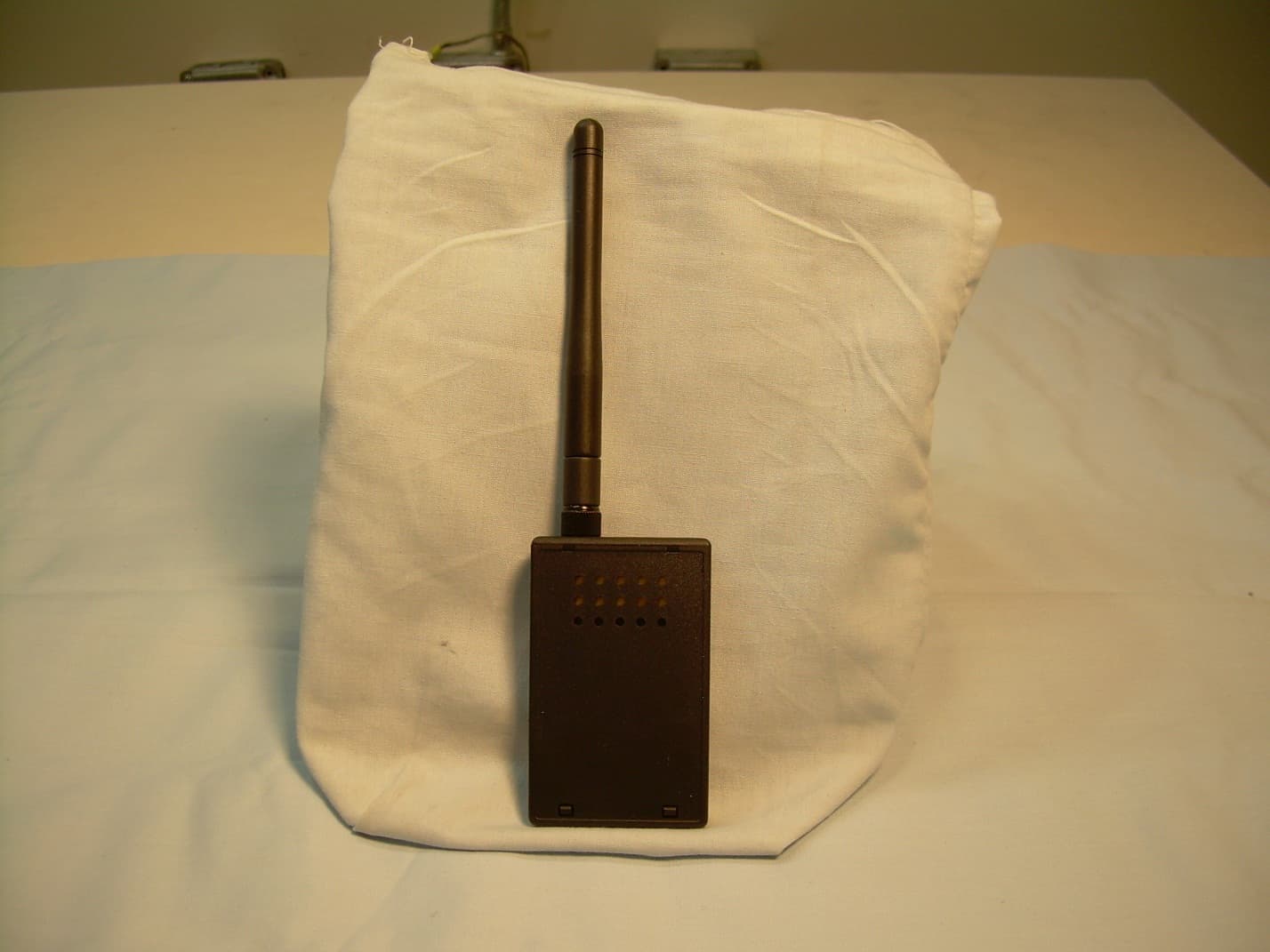
MHIZXT
Feb 12, 2014ZigBee Extender
Equipment Class
DTS - Digital Transmission System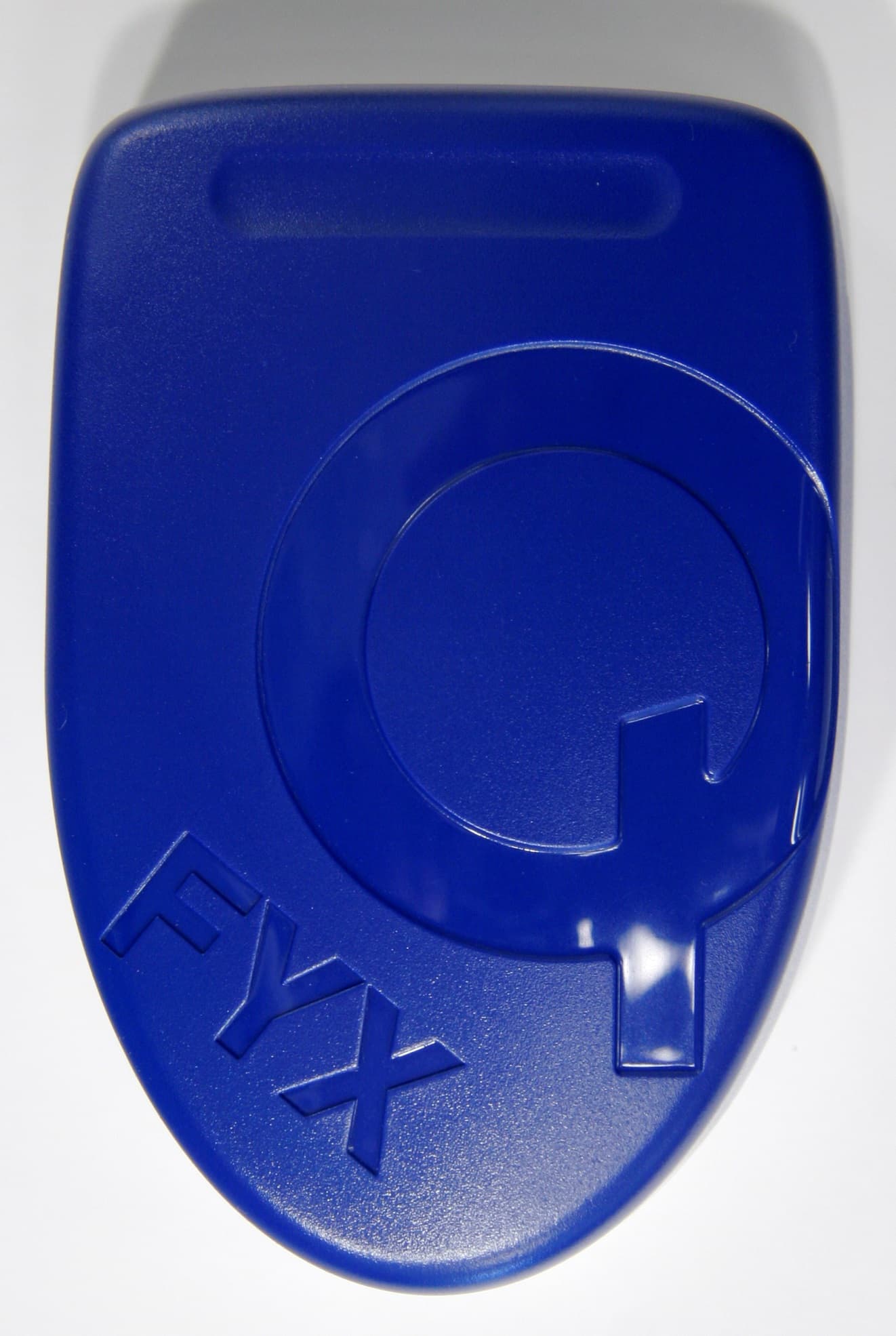
MHIFYX-1
May 11, 2013WLAN 802.11bgn 2.4GHz 1x1 and BLE v4.0 Bridge
Equipment Class
DTS - Digital Transmission System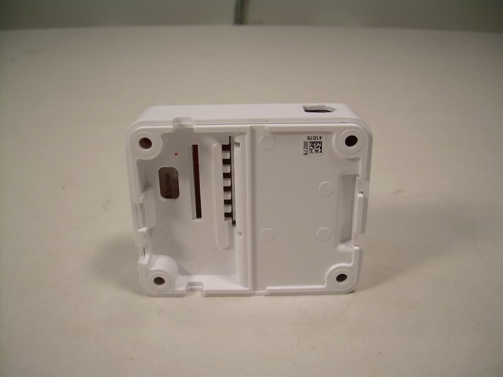
MHISUB10A
Feb 29, 2012Home Automation Appliance
Equipment Class
DTS - Digital Transmission System
MHIZGB20
Jan 06, 2011Card Access Security Sensor Bridge V2
Equipment Class
DTS - Digital Transmission SystemMHI751001
Nov 01, 1995PCMCIA Serial Interface Card
Equipment Class
JBP - Part 15 Class B Computing Device Peripheral