MHISUB10AHome Automation Appliance
Card Access Inc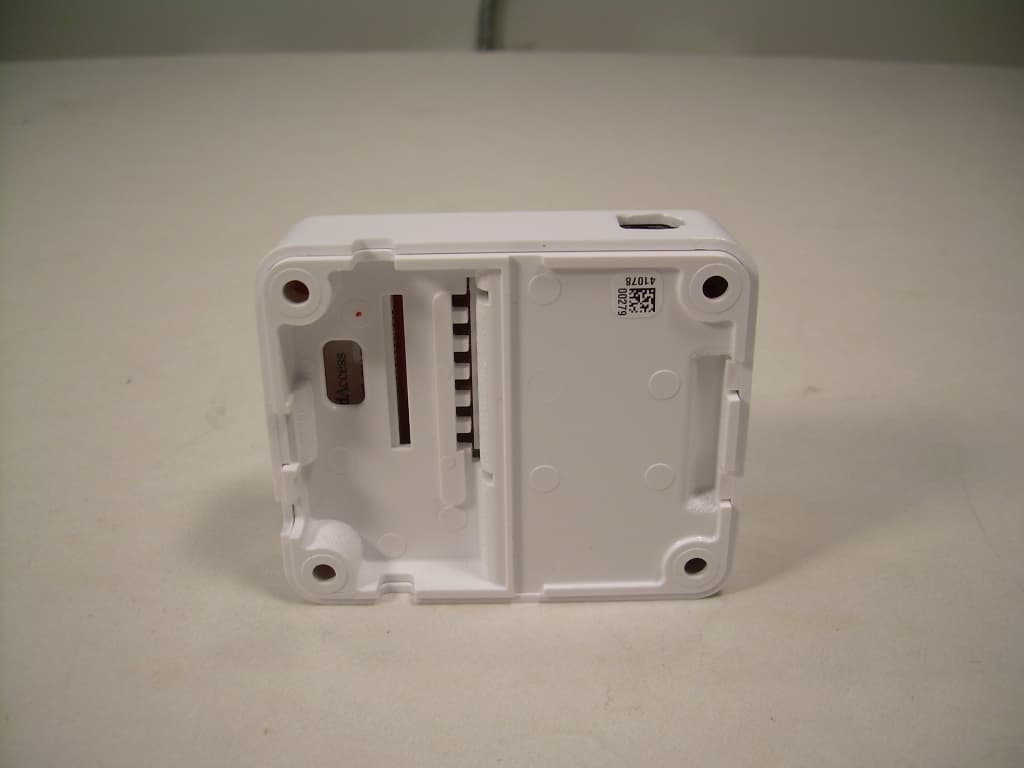
Click to zoom
Application Details
- Equipment Class
- DTS - Digital Transmission System
- Date of Grant
- Feb 29, 2012
- Application Purpose
- Original Equipment
- Date of Application
- Feb 29, 2012
- Equipment Note
- Home Automation Appliance
- Frequency Range
- 2405.00000000 - 2475.00000000
- Company
- Card Access Inc
- Country
- United States
Documents & Files
Document Text
Text extracted from the exhibit documents filed with the FCC. Open a document above to read the original.
Users Manual
• For help on the installation or operation of this product, email or call Card Access Product Support. Please provide your exact model number and the MAC ID/Serial Number for the device. You may contact Product Support by phone (801-748-4900, extension 2), by e-mail ([email protected]) or on the Internet at www.cardaccess-inc.com/automation/support. Regulatory Compliance The Card Access Smart Appliance Module complies with standards established by the following regulatory bodies: Federal Communications Commission (FCC), Conformité Européenne (CE), and Restriction of Hazardous Substances (RoHS). FCC FCC ID: MHISUB10A This device complies with Part 15 of the FCC Rules. Operation is subject to the following two conditions: (1) this device may not cause harmful interference, and (2) this device must accept any interference received, including interference that may cause undesired operation. This equipment has been tested and found to comply with the limits for a Class B digital device, pursuant to Part 15 of the FCC Rules. These limits are designed to provide reasonable protection against harmful interference in a residential installation. This equipment generates, uses, and can radiate radio frequency energy and, if not installed and used in accordance with the instructions, may cause harmful interference to radio communications. However, there is no guarantee that interference will not occur in a particular installation. If this equipment does cause harmful interference to radio or television reception, which can be determined by turning the equipment off and on, the user is encouraged to try to correct the interference by one or more of the following measures: • Reorient or relocate the receiving antenna. • Increase the separation between the equipment and receiver. • Connect the equipment into an outlet on a circuit different from that to which the receiver is connected. • Consult the dealer or an experienced radio/TV technician for help. IMPORTANT! Changes or modifications not expressly approved by Card Access, Inc. void the user’s authority to operate the equipment. Industry Canada IC 3681C-SUB10A This Class B digital apparatus complies with Canadian ICES-003. Cet appareil numérique de la classe B est conforme à la norme NMB-003 du Canada. This device complies with Industry Canada license-exempt RSS standard(s). Operation is subject to the following two conditions: (1) this device may not cause interference, and (2) this device must accept any interference, including interference that may cause undesired operation of the device. Le présent appareil est conforme aux CNR d’Industrie Canada applicables aux appareils radio exempts de licence. L’exploitation est autorisée aux deux conditions suivantes: (1) l’appareil ne doit pas produire de brouillage, et (2) l’utilisateur de l’appareil doit accepter tout brouillage radioélectrique subi, même si le brouillage est susceptible d’en compromettre le fonctionnement. CE We, Card Access, Inc. of 11778 South Election Road, Suite 260, Salt Lake City, Utah, 84020 USA, declare under our sole responsibility that the product, the Card Access Smart Appliance Module™, Model Number SUB10A-ZP to which this declaration relates, is in conformity with the following standards and / or other normative documents: EN60950, EN55022, N55024 We hereby declare that the above named product is in conformity with the essential requirements and other relevant provisions of Directive 1999/5/EC. The conformity assessment procedure referred to in Article 10(3) and detailed in Annex II of Directive 1999/5/EC has been followed. SUB-ZERO / WOLF Smart Appliance Module™ For Home Automation™ Supported Models and Requirements The Card Access Smart Appliance Module™ is designed for installation into specific SUB-ZERO / Wolf appliances. Installation should be completed by an authorized Control4® Dealer. The module requires a Control4 Home Controller running Composer 2.1.0 or higher. Important Safety Instructions WARNING! You should install this device in accordance with all national and local electrical codes. IMPORTANT! Improper use or installation of this device can result in LOSS OF/DAMAGE TO PROPERTY. IMPORTANT! Using this product in any manner other than outlined in this document voids your warranty. Also, Card Access is NOT responsible or otherwise liable in any way for any damage resulting from the misuse of this product. See the section of this document entitled WARRANTY for details. What Is Included. You will find the following items inside the Smart Appliance Module package: • Bubble bag containing one (1) Wireless Smart Appliance Module - Tray assembly (to be mounted to a wall or other flat surface) - Cover assembly and attached radio/logic board ( to be connected to the Tray Assembly) • Installation Guide / DriverWorks Driver Download Web Address • One (1) RJ-12 Control Cable • Two (2) Cable Zip Ties • One (1) Velcro Attachment Strip Pre-Installation The Card Access Smart Appliance Module™ integrates quickly and easily into your Control4 system. Prior to installing the Smart Appliance Module, the Control4 Controller being used in the project will need to be assigned a Control4, 4Store account. To create a 4Store account follow the directions below: • Go to http://www.4store.com and create an account for the Home Controller in the project. • Download the SUB-ZERO or WOLF app: SUB-ZERO for the refrigerator, and WOLF for the oven. • After loading Composer, go to the Agents Tab and add the 4Store Agent. Enter the account information for the 4Store account you have just created. Save the information and click the update button. This will load the SUB-ZERO app and make it appear on the Navigator. • The Home Controller must be running version 2.1 or higher for correct operation. If the Home Controller is running an earlier version and needs to be updated, ensure the update is completed prior to installing the SUB-ZERO / WOLF Smart Appliance Module. • After the 4S…
Text truncated - open the document above for the full version.
Block Diagram
Reed Switch Thermistor LEDs Processor 8MHz Crystal 32kHz Crystal Zigbee Radio 2.4GHz 16MHz Crystal RF Switch PA RF Switch LNA Antenna RS-485 Converter 6P6C Connector 12VDC SUB10A-ZP BLOCK DIAGRAM
External Photos
Front View of the EUT Back View of the EUT
ID Label/Location Info
SUB10A‐ZP LABEL AND PLACEMENT:
Internal Photos
Internal View of the EUT – Back Housing Removed View of the Component Side of the PCB
Operational Description
11778 So. Election Road, Suite 260 Salt Lake City, UT 84020 Ph. (801) 748-4900 Fax (801) 748-4901 SUB10A-ZP RS-485 to Zigbee Operation Description This device (SUB10A-ZP) is designed to work with the Control4 home automation system and should be installed according to the instructions in the User Manual installation guide. From that point the operation is automatic with no user intervention. It is designed to connect to appliances such as refrigerators and ovens to allow them to be incorporated into the automation system. It also has an internal reed switch that can be activated from an external magnet. There is an internal thermistor for sensing ambient temperature. The device connects to the appliance through a 6P6C connector which provides power to the device and an RS-485 serial connection. It is a serial-to-Zigbee bridge that creates a packet and transmits it to the system allowing communication between the system and the appliance. The result of this information and any action associated with it depends on how the installer programs the Control4 system. In addition to the packet transmissions generated by appliance events, the unit will also periodically check in with the system. The radio is a Zigbee radio using 15 channels from 2.405 GHz up to 2.465 GHz. The transmit power is 10dBm. This is an 802.15.4 radio and it uses O-QPK modulation.
Parts List/Tune Up Info
Daughter Card Part ReferenceDescriptionManufacturer 1Mfg 1 Part Number C1 C20.1uF ±10% 100V X7R 0805 Ceramic Chip CapacitorTaiyo YudenHMK212B7104KG-T C310uF ±10% 16V X5R 0805 Ceramic Chip CapacitorMurataGRM21BR61C106KE15L J113x1 100mil SMT Termination Type Header THRSullinsGEC13SBSN-M89 J2Modular Connector 6 Position R/A SMTMolex44144-0005 U13.3V Low Power 30Mbps RS485/RS422 Transceiver SO8IntersilISL43485IBZ-T Main Unit Part ReferenceDescriptionManufacturer 1Mfg 1 Part Number C1,C2,C3,C10,C 11,C12,C17,C35, C60,C66,C68 0.1uF 10V 10% X5R 0402 Ceramic SMDKemetC0402C104K8PACTU C48,C560.1uF 100V 10% X7R 0805 Ceramic SMD Kemet Taiyo Yuden C0805C104K1RACTU HMK212B7104KG-T C50, C511.0uF 6.3V 20% X5R 0402 Ceramic SMD Murada Panasonic GRM155R60J105KE19D ECJ-0EB0J105M C4,C7,C54,C550.01uF 16V 10% X7R 0402 Ceramic SMDKemetC0402C103K3RACTU C5,C6,C15,C1618pF 50V 5% C0G 0402 Ceramic SMDKemetC0402C180J5GACTU C8,C9,C13,C18, C19,C20,C47 68pF 50V 5% C0G 0402 Ceramic SMDKemetC0402C680J5GAC C14,C41,C42,C4 3,C52,C53,C57 10uF 6.3V 10% X5R 0805 Ceramic SMD Panasonic AVX ECJ-2FB0J106K 08056D106KAT2A C25,C26,C27,C2 9,C30,C32,C33,C 34,C36,C37,C38 8.2pF 50V ±0.25pF NP0 0402 Ceramic SMD AVX Murata 04025A8R2CAT2A GRM1555C1H8R2CZ01 D C245.6pF 50V ±0.25pF C0G 0402 Ceramic SMD Murata AVX GRM1555C1H5R6DZ01 D 04025A5R6CAT2A C28,C312.2pF 50V 0.25pF C0G 0402 Ceramic SMDYAGEOCC0402CRNPO9BN2R2 C21,C23,C39 1.0pF 50V 0.25pF COG 0402 HFLLC SMDMurata GJM1555C1H1R0CB01 D C401.8pF 50V 0.25pF C0G 0402 Ceramic SMD Murata GJM1555C1H1R8CB01 D C44,C454.7uF 6.3V 20% X5R 0603 Ceramic SMDPanasonicECJ-1VB0J475M C49,C58,C59,C6 1,C63,C64,C65,C 7110uF 35V +80-20% Y5V 1206 Ceramic SMDTaiyo Yuden GMK316F106ZL-T C73220uF 35V 20% Elect 8mmDx11.5mmT Rad THPanasonicECA-1VM221BJ D5,D1 MMBD1505A, 200mA 200V Dual Low Leakage Diodes (SMD) Common AnodeFairchildMMBD1505A D71A 20V Schottky Rectifier Diode (SMD) On Semi MICRO SEMI MBRM120LTG UPS120ETR13 D2 MMBD1504A, 200mA 200V Dual Low Leakage Diodes (SMD) Common CathodeFairchildMMBD1504A J11TH Header 5MM Pitch 6 PositionRia Connect31046106 LED1,LED2Bi-color LED (green/red) in 0603-size SMD packageAgilentHSMF-C165 L13.3uH 30mA 10% 0805 monolithic SMDMurataLQM21NN3R3K10L L2,L47.5nH 5% 0402 HF Multilayer Chip InductorMurataLQG15HS7N5J02D L35.6nH 5% 0402 HF Multilayer Chip InductorMurataLQG15HS5N6S02D L5,L1010nH 5% 0402 HF Multilayer Chip InductorMurataLQG15HS10NJ02D L63.6nH 5% 0402 HF Multilayer Chip InductorMurataHK10053N6S-T L7HF Monolithic Chip Inductor, 2.7nH ±0.3nH LQG (SMD)Murata LQG15HS2N7S02D L81.8uH 50mA 10% 0805 SMDMurataLQM21NN1R8K10D L968uH 220mA 10% 1812 Chip Coil SMDMurata LQH43CN680K03L L11,L134.7nH 0.1nH 0402 HF Film Chip InductorMurataLQP15MN4N7B02D L12,L141.8nH 0.1nH 0402 HF Film Chip InductorMurataLQP15MN1N8B02D Q1,Q2NPN Silicon RF Transistor Infineon Technologies BFP420E6327 Q3NPN General Purpose AmplifierDiodes Inc. MMBT2222A-7-F Q4,Q6,Q7,Q9, Q101.25W, 1.8V (G-S), P-Channel MOSFETFairchild FDN306P R1,R31,R35,R39, R40,R41,R48 1.0M ohm 5% 1/16W 0402 Chip Resistor KOARK73B1ETTP105J R32.0 ohm 5% 1/16W 0402 Chip ResistorKOARK73B1ETTP2R0J R443.2k ohm 1% 1/16W 0402 Chip ResistorDaleCRCW04024322FKEA R23,R24,R46,R4 7,R531.0k ohm 5% 1/8W 0805 Chip ResistorDaleCRCW08051K00JNEA R622.0 ohm 1% 1/16W 0402 Chip Resistor YageoRC0402FR-0722RL R7,R37150 ohm 1% 1/16W 0402 Chip ResistorPanasonic ERJ-2RKF1500X R12,R13,R14,R3 668 ohm 5% 1/16W 0402 Chip ResistorPanasonicERJ2GEJ680X R5,R8,R426.81k ohm 1% 1/16W 0402 Chip Resistor KOARK73H1ETTP6811F R1024.9k ohm 1% 1/16W 0402 Chip Resistor Dale KOA CRCW04022492FKEA RK73H1ETTP2492F R11,R20,R21,R2 8,R29,R34,R25,R 5910.0k ohm 1% 1/16W 0402 Chip Resistor Dale KOA CRCW04021002FKEA RK73H1ETTP1002 R15,R17,R38,R5 60 ohm 0402 Chip JumperRohmMCR01MZSJ000 R45,R57,R58,R6 00 ohm 0805 Chip JumperDaleCRCW08050000ZOEA R2210k ohm 5% 0805 NTC ThermistorMurataNCP21XV103J03RA R26,R33,R44 340k ohm 1% 1/16W 0402 Chip Resistor KOARK73H1ETTP3403F R304.32k ohm 1% 1/16W 0402 Chip ResistorPanasonicERJ2RKF4321X R541.0k ohm 5% 1/16W 0402 Chip Resistor Yageo Rohm RC0402JR-071KL MCRC01MZPJ102 R271 ohm 5% 1/16W 0402 Chip ResistorYageoRC0402JR-071RL SW4 Switch,Tactile, 6mm, Height 4.3mm, 160g, No Ground, SMD C&K Components PTS645SM43SMTR LFS SW2Switch Reed MAG Plastic SMTCoto Technology CT10-1540-G1 U1 1Mb SPI DataFlash SO8 AtmelAT45DB011D-SH-B U2Atmega128L 8-bit microcontroller (128K programmable flash) AtmelATMEGA128L-8MU U32.4GHz IEEE 802.15.4/ZigBee-ready RF Tranceiver CC2420 EmberEM2420/TR U4,U6GaAs MMIC for L, S-band SPDTNECUPG2214TB-A U5NC7WZ04, UHS Dual Inverter (w/ TinyLogic)FairchildNC7WZ04P6X U81.5A Inverting Swtching RegulatorOn Semi MC34063ADR2G U93.3V Regulated, Low-ripple Charge Pump Texas Instruments TPS60213DGS U12Reset Monitor 2.63V SC70On SemiMAX803SQ263T1G Y132.786KHz 12.5P 20PPM SMD CrystalCitizen CMR200T- 32.768KDZFUT Y28.000MHz 18P 20PPM SMD CrystalMurataCSTCE8M00G55-RO Y316.000MHz 18P 20PPM SMD CrystalMMDI18PC1-16.000MHZT Z1TVS_Bidirectional_5V_SOT23_6 Comchip Technology Corporation CEBS065V0-G Z2TVS_Bidirectional_36V_SMBOn Semi1SMB36CAT3G
RF Exposure Info
Maximum Permissible Exposure Calculation The Card Access device, model number SUB10A-ZP, has an RF power into the antenna of 10 dBm or 10 mW. The antenna gain is 2 dBi. The unit is designed to be mounted in a fixed position near an appliance of a house and therefore the distance from the antenna to any person will typically be greater than 1 meter. The power density for continuous transmit would be calculated as: (10mW) (2) 0.16 W/cm 2 4(100cm) 2 The limit for general population uncontrolled exposure is 1 mW/cm 2 . Even if the device was as close as 2 cm, the power density would be 0.4 mW/cm 2 . The exposure limit is also time-averaged. This device transmits in short bursts of typically 200mS or less, with several seconds between transmissions (possibly several minutes). Time-averaged over 30 minutes, the exposure is much less than continuous transmit.
Schematics
55 44 33 22 11 D D C C B B A A MODE SELECT DNS DNS FIREBUTTON ID BUTTON DNSDNS DNS DNSDNS DNS DNS DNS DNSDNS DNS DNS DNS DNS THERMISTOR FL_CS_LEN_FL_L FL_MOSI/TDOFL_SCKFL_CS_LFL_MISO EN_FL_L FL_MISO FL_SCK +3.3V +3.3V+3.3V +3.3V +3.3V +3.3V +3.3V +3.3V +3.3V +3.3V TDI 4TMS 4TCK 4 FL_MOSI/TDO 4PA0 4PA1 4PA2 4PA3 4PA4 4PA5 4PA6 4PA7 4AREF 4 M 4 SDA 4RXD1 4SCL 4TXD1 4RESET 3,4 PWR1 3 PWR2 3 V_BATT 3 VREG_EN 2 SI 2 RXD0 4 RADIO_CAP_CHRG 3 CS_L 2 SNZ_L 3 RESET_L 2 RADIO_PWR_ON 3 FIFOP 2 SO 2 EXT_V 3 SFD 2 CCA 2 FIFO 2 TXD0 4 OC3A 4 T3 3,4 SCK 2,4 HUMIDITY 4TEMPERATURE 4 ICP3 4 PG2 4 CHIPCAP_PWR 4 TitleDocument NumberDate: Sheet of Proprietary 1 5 Wednesday, January 11, 2012 SUB10A-ZP - CPUC:\PROJECTS\SUB ZERO\DAUGHTERCARD\SCHEMATIC\SCH-SUB10A-ZP-100.DSN TitleDocument NumberDate: Sheet of Proprietary 1 5 Wednesday, January 11, 2012 SUB10A-ZP - CPUC:\PROJECTS\SUB ZERO\DAUGHTERCARD\SCHEMATIC\SCH-SUB10A-ZP-100.DSN TitleDocument NumberDate: Sheet of Proprietary 1 5 Wednesday, January 11, 2012 SUB10A-ZP - CPUC:\PROJECTS\SUB ZERO\DAUGHTERCARD\SCHEMATIC\SCH-SUB10A-ZP-100.DSN R2110.0k C660.1uF C74DNS ATmega128L U2 PEN_L 1 RXD0/(PDI) PE0 2 (TXD0/PDO) PE1 3 (XCK0/AIN0) PE2 4 (OC3A/AIN1) PE3 5 (OC3B/INT4) PE4 6 (OC3C/INT5) PE5 7 (T3/INT6) PE6 8 (ICP3/INT7) PE7 9 (SS_L) PB0 10 (SCK) PB1 11 (MOSI) PB2 12 (MISO) PB3 13 (OC0) PB4 14 (OC1A) PB5 15 (OC1B) PB6 16 PG0(WR_L) 33 PG1(RD_L) 34 PC0 (A8) 35 PC1 (A9) 36 PC2 (A10) 37 PC3 (A11) 38 PC4 (A12) 39 PC5 (A13) 40 PC6 (A14) 41 PC7 (A15) 42 PG2(ALE) 43 PA7 (AD7) 44 PA6 (AD6) 45 PA5 (AD5) 46 PA4 (AD4) 47 PA3 (AD3) 48 PA2 (AD2) 49 PA1 (AD1) 50 PA0 (AD0) 51 VCC2 52 GND2 53 PF7 (ADC7/TDI) 54 PF6 (ADC6/TDO) 55 PF5 (ADC5/TMS) 56 PF4 (ADC4/TCK) 57 PF3 (ADC3) 58 PF2 (ADC2) 59 PF1 (ADC1) 60 PF0 (ADC0) 61 AREF 62 AGND 63 AVCC 64 GND3 65 (OC2/OC1C) PB7 17 TOSC2/PG3 18 TOSC1/PG4 19 RESET_L 20 VCC1 21 GND1 22 XTAL2 23 XTAL1 24 (SCL/INT0) PD0 25 (SDA/INT1) PD1 26 (RXD1/INT2) PD2 27 TXD1/INT3) PD3 28 (ICP1) PD4 29 (XCK1) PD5 30 (T1) PD6 31 (T2) PD7 32 Si2305DS Q10 3 1 2 R411.0M R52DNS R391.0M D3 MMBD1504 1 2 3 L13.3uH C618pF R2010.0k R24 1.0k Q5 MMBT2222A 1 32 SW2REED 1 2 SW4PUSH-RT R13 68 C30.1uF R471.0k Y1 32.768kHz C20.1uF R33340k R170 R11.0M C40.01uF R600 C10.1uF C480.1uF C600.1uF R12 68 R49100 J11Header 123456 C460.1uF Q8 MMBT2222A 1 32 R504.32k R5910.0k R580 R18DNS C560.1uF RL2 G6L-1F 24 58 R9 DNS R401.0M T R2210k R570 C690.1uFR531.0k R43DNS 0 Z1 CEBS065V 1 5 3 6 2 4 SW1PUSH-RT RED GRN LED1 HSMF-C165 13 24 RL1 G6L-1F 24 58 R19DNS R36 68 SPK1 R450 R14 68 R44340k Y2 8.000MHz R61 0 U1 AT45DB011D-SH SO 8 GND 7 RST_L 3 WP_L 5 CS_L 4 SI 1 VCC 6 SCK 2 R23 1.0k RED GRN LED2 HSMF-C165 13 24 R461.0k C518pF R514.32k 55 44 33 22 11 D D C C B B A A UPG2214TB CNT1 CNT2 IN->OUT1 IN->OUT2 DNS 0 0 3.3 3.3 ON ON OFF OFF VPA VLNA +3.3VZ +3.3VPA +3.3VLNA +3.3VPA +3.3VLNA +3.3VZ +1.8V +3.3VPA+3.3VLNA +3.3VZ +1.8V +1.8V +1.8V +1.8V +1.8V +3.3VPA +1.8V +3.3VLNA +1.8V +3.3VZ +1.8V +1.8V VREG_EN 1SI 1CS_L 1RESET_L 1SO 1SCK 1,4FIFOP 1CCA 1SFD 1FIFO 1 TitleDocument NumberDate: Sheet of Proprietary 2 5 Wednesday, January 11, 2012 SUB10A-ZP - Zigbee RadioC:\PROJECTS\SUB ZERO\DAUGHTERCARD\SCHEMATIC\SCH-SUB10A-ZP-100.DSN TitleDocument NumberDate: Sheet of Proprietary 2 5 Wednesday, January 11, 2012 SUB10A-ZP - Zigbee RadioC:\PROJECTS\SUB ZERO\DAUGHTERCARD\SCHEMATIC\SCH-SUB10A-ZP-100.DSN TitleDocument NumberDate: Sheet of Proprietary 2 5 Wednesday, January 11, 2012 SUB10A-ZP - Zigbee RadioC:\PROJECTS\SUB ZERO\DAUGHTERCARD\SCHEMATIC\SCH-SUB10A-ZP-100.DSN C1618pF L47.5nH C1518pF C268.2pF CC2420 U3 VCO_GUARD 1 AVDD_VCO 2 AVDD_PRE 3 AVDD_RF1 4 GND1 5 RF_P 6 TXRX_SWITCH 7 RF_N 8 GND2 9 AVDD_SW 10 NC1 11 NC2 12 GND_CENTER 49 DVDD3.3 25 DVDD1.8 26 SFD 27 CCA 28 FIFOP 29 FIFO 30 CS_L 31 SCLK 32 SI 33 SO 34 DVDD_RAM 35 NC5 36 AVDD_XOSC16 37 XOSC16_Q2 38 XOSC16_Q1 39 NC6 40 VREG_EN 41 VREG_OUT 42 VREG_IN 43 AVDD_IF1 44 R_BIAS 45 ATEST2 46 ATEST1 47 AVDD_CHP 48 NC3 13 AVDD_RF2 14 AVDD_IF2 15 NC4 16 AVDD_ADC 17 DVDD_ADC 18 DGND_GUARD 19 DGUARD 20 RESET_L 21 DGND 22 DSUB_PADS 23 DSUB_CORE 24 C328.2pF R86.81k C868pF R4 43.2k C282.2pF R16 DNS 0 R56.81k C308.2pF C110.1uF C120.1uF R1110.0k C231.0pF J4 SMA C1368pF C968pF C1868pF C378.2pF C211.0pF U4 UPG2214TB OUT1 1 GND 2 OUT2 3 CNT2 4 IN 5 CNT1 6 Y3 16.000MHz L510nH C170.1uF L35.6nH L72.7nH C2068pF L114.7nH C245.6pF C312.2pF R37150 Q3 MMBT2222A 1 32 R1024.9k L141.8nH C1410uF PCB1 2.4 GHz 1 C550.01uF L27.5nH Q2 BFP420 1 32 4 C540.01uF L1010nH C100.1uF L121.8nH C258.2pF R150 R380 R7150 C388.2pF R622.0 U5 NC7WZ04 A1 1 GND 2 A2 3 Y2 4 VCC 5 Y1 6 C22DNS R32.0 C298.2pF C391.0pFC401.8pF C278.2pF C350.1uF L63.6nH Q1 BFP420 1 32 4 C70.01uF L134.7nH C1968pF C368.2pF C348.2pF U6 UPG2214TB OUT1 1 GND 2 OUT2 3 CNT2 4 IN 5 CNT1 6 C338.2pF 55 44 33 22 11 D D C C B B A A DNS 4.14V DNS DNS DNS VIN VIN +3.3V VIN +3.3VZ +3.3V +3.3V Vdc 4 BATTERY 4 PWR1 1 PWR2 1 V_BATT 1SNZ_L 1EXT_V 1RADIO_CAP_CHRG 1RADIO_PWR_ON 1T3 1,4 RESET 1,4 TitleDocument NumberDate: Sheet of Proprietary 3 5 Wednesday, January 11, 2012 SUB10A-ZP - Power SupplyC:\PROJECTS\SUB ZERO\DAUGHTERCARD\SCHEMATIC\SCH-SUB10A-ZP-100.DSN TitleDocument NumberDate: Sheet of Proprietary 3 5 Wednesday, January 11, 2012 SUB10A-ZP - Power SupplyC:\PROJECTS\SUB ZERO\DAUGHTERCARD\SCHEMATIC\SCH-SUB10A-ZP-100.DSN TitleDocument NumberDate: Sheet of Proprietary 3 5 Wednesday, January 11, 2012 SUB10A-ZP - Power SupplyC:\PROJECTS\SUB ZERO\DAUGHTERCARD\SCHEMATIC\SCH-SUB10A-ZP-100.DSN L8 1.8uH R31 1.0M Si2305DS Q6 3 1 2 C511.0uF C6410uF D7 MBRM120LG 12 R481.0M U11MAX803 1 2 3 C454.7uF C680.1uF C6510uF L968uH C7110uF C5210uF R304.32k C4768pF R26340k R541.0k R55 DNS C5910uF C670.1uF U9 TPS60213 LBI 1 GND 2 C1- 3 C1+ 4 OUT 5 C2+ 6 IN 7 C2- 8 SNZ_L 9 LBO 10 Si2305DS Q4 3 1 2 C4310uF C4110uF R2810.0k U8 MC34063A Sw Col 1 Sw Emit 2 Timing Cap 3 GND 4 Comp Inv In 5 VCC 6 Ipk 7 Driver Col 8 R426.81k C4910uF C501.0uF C5710uF Si2305DS Q9 3 1 2 J5 2 AA Batt Holder +| C5310uF Z236V 12 C6110uF C6310uF Si2305DS Q7 3 1 2 R2510.0k D1 MMBD1505 12 3 R351.0M R32 D2 …
Text truncated - open the document above for the full version.
Test Report
Nemko-CCL, Inc. 1940 West Alexander Street Salt Lake City, UT 84119 801-972-6146 Test Report Certification Test Of: SUB10A-ZP FCC ID: MHISUB10A Test Specification: FCC PART 15, Subpart C Test Report Serial No: 193697-3.1 Applicant: Card Access Inc. 11778 South Election Road, Suite 260 Salt Lake City, UT 84020 Date of Test: December 12 & 13, 2011 Issue Date: December 21, 2011 Accredited Testing Laboratory By: NVLAP Lab Code 100272-0 Nemko-CCL, Inc. TEST REPORT: 193697-3.1 FCC ID#: MHISUB10A Page 2 of 55 CERTIFICATION OF ENGINEERING REPORT This report has been prepared by Nemko-CCL, Inc. to document compliance of the device described below with the requirements of Federal Communications Commission (FCC) Part 15, Subpart C. This report may be reproduced in full, partial reproduction may only be made with the written consent of the laboratory. The results in this report apply only to the sample tested. - Applicant: Card Access Inc. - Manufacturer: Card Access Inc. - Brand Name: Card Access - Model Number: SUB10A-ZP - FCC ID Number: MHISUB10A On this 21 st day of December 2011, I, individually, and for Nemko-CCL, Inc., certify that the statements made in this engineering report are true, complete, and correct to the best of my knowledge, and are made in good faith. Although NVLAP has recognized that the Nemko-CCL, Inc. EMC testing facilities are in good standing, this report must not be used to claim product certification, approval, or endorsement by NVLAP, NIST, or any agency of the federal government. Nemko-CCL, Inc. Tested by: Norman P. Hansen EMC Technician Nemko-CCL, Inc. TEST REPORT: 193697-3.1 FCC ID#: MHISUB10A Page 3 of 55 TABLE OF CONTENTS PAGE SECTION 1.0 CLIENT INFORMATION .................................................................................4 SECTION 2.0 EQUIPMENT UNDER TEST (EUT) ..................................................................5 SECTION 3.0 TEST SPECIFICATION, METHODS & PROCEDURES .............................9 SECTION 4.0 OPERATION OF EUT DURING TESTING ..................................................15 SECTION 5.0 SUMMARY OF TEST RESULTS ...................................................................16 SECTION 6.0 MEASUREMENTS, EXAMINATIONS AND DERIVED RESULTS ..........17 APPENDIX 1 TEST PROCEDURES AND TEST EQUIPMENT ..........................................36 APPENDIX 2 PHOTOGRAPHS ................................................................................................44 APPENDIX 3 TRANSMITTER DUTY CYCLE CALCULATIONS .....................................55 Nemko-CCL, Inc. TEST REPORT: 193697-3.1 FCC ID#: MHISUB10A Page 4 of 55 SECTION 1.0 CLIENT INFORMATION 1.1 Applicant: Company Name: Card Access Inc. 11778 South Election Road, Suite 260 Salt Lake City, UT 84020 Contact Name: James A. Stout Title: Vice President Engineering 1.2 Manufacturer: Company Name: Card Access Inc. 11778 South Election Road, Suite 260 Salt Lake City, UT 84020 Contact Name: James A. Stout Title: Vice President Engineering Nemko-CCL, Inc. TEST REPORT: 193697-3.1 FCC ID#: MHISUB10A Page 5 of 55 SECTION 2.0 EQUIPMENT UNDER TEST (EUT) 2.1 Identification of EUT: Brand Name: Card Access Model Number: SUB10A-ZP Serial Number: 4107800279 2.2 Description of EUT: The SUB10A-ZP is a device that bridges between an RS-485 signal from an appliance such as a refrigerator or stove to Zigbee, to allow the appliance to be joined into a Zigbee network. Status and control signals will be passed between the appliance and the Zigbee controller. Power to the device comes through the same connector as the RS-485 signals. For testing, power to the SUB10A-ZP was supplied over the RS-485 port using a CUI 41-12-300, 12 VDC at 300 mA power supply or a V-infinity 3A-061WP12, 9 – 12 VDC at 660 mA, power supply. The SUB10A-ZP transceiver operates using 15 channels, spaced 5 MHz apart, in the 2400 MHz to 2483.5 MHz frequency band. The SUB10A-ZP transceiver uses a trace on the PCB for the antenna. Testing was performed with the EUT placed on 3 orthogonal axes and at the upper channel (2475 MHz), the middle channel (2440 MHz), and the lower channel (2405 MHz). See the plots of the channels below. dBm 0 -10 -20 -30 -40 -50 -60 -70 -80 -90 -100 Trace A Start: 2.402500 GHzStop: 2.427500 GHz Trace A Lower 5 channels 1 1 2.405000 GHz -5.4000 dBm 2 2 2.410075 GHz -5.1000 dBm 3 3 2.415075 GHz -5.8000 dBm 4 4 2.420050 GHz -5.8000 dBm 5 5 2.425025 GHz -5.8000 dBm Nemko-CCL, Inc. TEST REPORT: 193697-3.1 FCC ID#: MHISUB10A Page 6 of 55 dBm 0 -10 -20 -30 -40 -50 -60 -70 -80 -90 -100 Trace A Start: 2.427500 GHzStop: 2.452500 GHz Trace A Middle 5 channels 11 2.430000 GHz -6.5000 dBm 2 2 2.435075 GHz -5.5000 dBm 3 3 2.440075 GHz -6.2000 dBm 4 4 2.445050 GHz -6.1000 dBm 5 5 2.450025 GHz -5.3000 dBm dBm 0 -10 -20 -30 -40 -50 -60 -70 -80 -90 -100 Trace A Start: 2.452500 GHzStop: 2.477500 GHz Trace A Upper 5 channels 1 1 2.455000 GHz -7.4000 dBm 2 2 2.460075 GHz -8.1000 dBm 3 3 2.465075 GHz -8.2000 dBm 4 4 2.470050 GHz -7.6000 dBm 5 5 2.475025 GHz -7.5000 dBm This report covers the circuitry of the devices subject to FCC Part 15, Subpart C. The circuitry of the device subject to FCC Part 15, Subpart B has been tested and found to comply. See Nemko-CCL report #193697-2.1. 2.3 EUT and Support Equipment: The EUT and support equipment used during the test are listed below: Nemko-CCL, Inc. TEST REPORT: 193697-3.1 FCC ID#: MHISUB10A Page 7 of 55 Brand Name Model Number Serial Number FCC ID Number or Compliance Description Name of Interface Ports / Interface Cables BN: Card Access MN: SUB10A-ZP ( Note 1) SN: 4107800279 MHISUB10A RS-485 to Zigbee Adapter See Section 2.4 BN: Lenovo MN: T510 SN: R9-AK6TH DoC Computer USB/USB cable BN: Parallax MN: USBto232 SN: None None USB to RS-232 Adapter USB/USB cable RS-232/DB9 connector BN: Serial Comm MN: CON-485-PIE SN: None None RS-232 to RS-485 Adapter RS-232/DB9 connector RS485/DB9 connector with attached 6 conductor ribbon cable to Modular 6 pin connector with 6 conductor mod…
Text truncated - open the document above for the full version.
Test Setup Photos
Front View Radiated Disturbance Worst Case Configuration On-Edge Placement Back View Radiated Disturbance Worst Case Configuration On-Edge Placement Front View Radiated Disturbance Configuration – Vertical Placement Back View Radiated Disturbance Configuration – Vertical Placement View Radiated Disturbance Configuration – Horizontal Placement Front View Conducted Disturbance Worst Case Configuration Back View Conducted Disturbance Worst Case Configuration
Contact Information
Applicant
James A Stout(Vice President Engineering)
Test Firm
VPI TechnologyJason Stewart
[email protected]801-495-2310
Technical Specifications
| # | Rule Parts | Frequency Range | Power Output |
|---|---|---|---|
| 1 | 15C | 2.40 GHz - 2.48 GHz | 11.46 mW |
Other Applications from Card Access Inc
MHIZXT
Feb 12, 2014ZigBee Extender
Equipment Class
DTS - Digital Transmission System
MHIFYX-1
May 11, 2013WLAN 802.11bgn 2.4GHz 1x1 and BLE v4.0 Bridge
Equipment Class
DTS - Digital Transmission System
MHIZGB20
Jan 06, 2011Card Access Security Sensor Bridge V2
Equipment Class
DTS - Digital Transmission System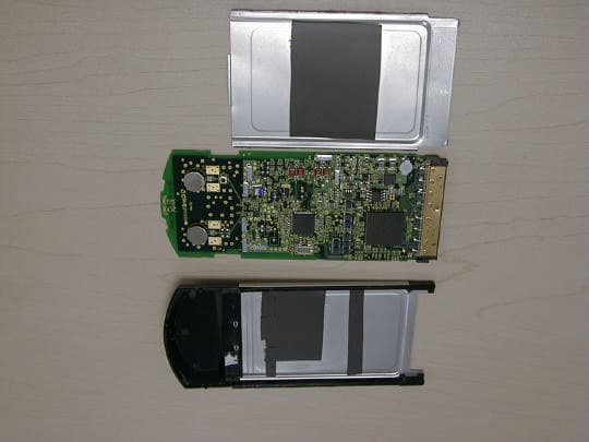
MHI-CAWCB500
Oct 14, 20015.15 - 5.35 GHz UNII CardBusTransceiver model CAWC
Equipment Class
NII - Unlicensed National Information Infrastructure TXMHI751001
Nov 01, 1995PCMCIA Serial Interface Card
Equipment Class
JBP - Part 15 Class B Computing Device Peripheral