MHIZXTZigBee Extender
Card Access Inc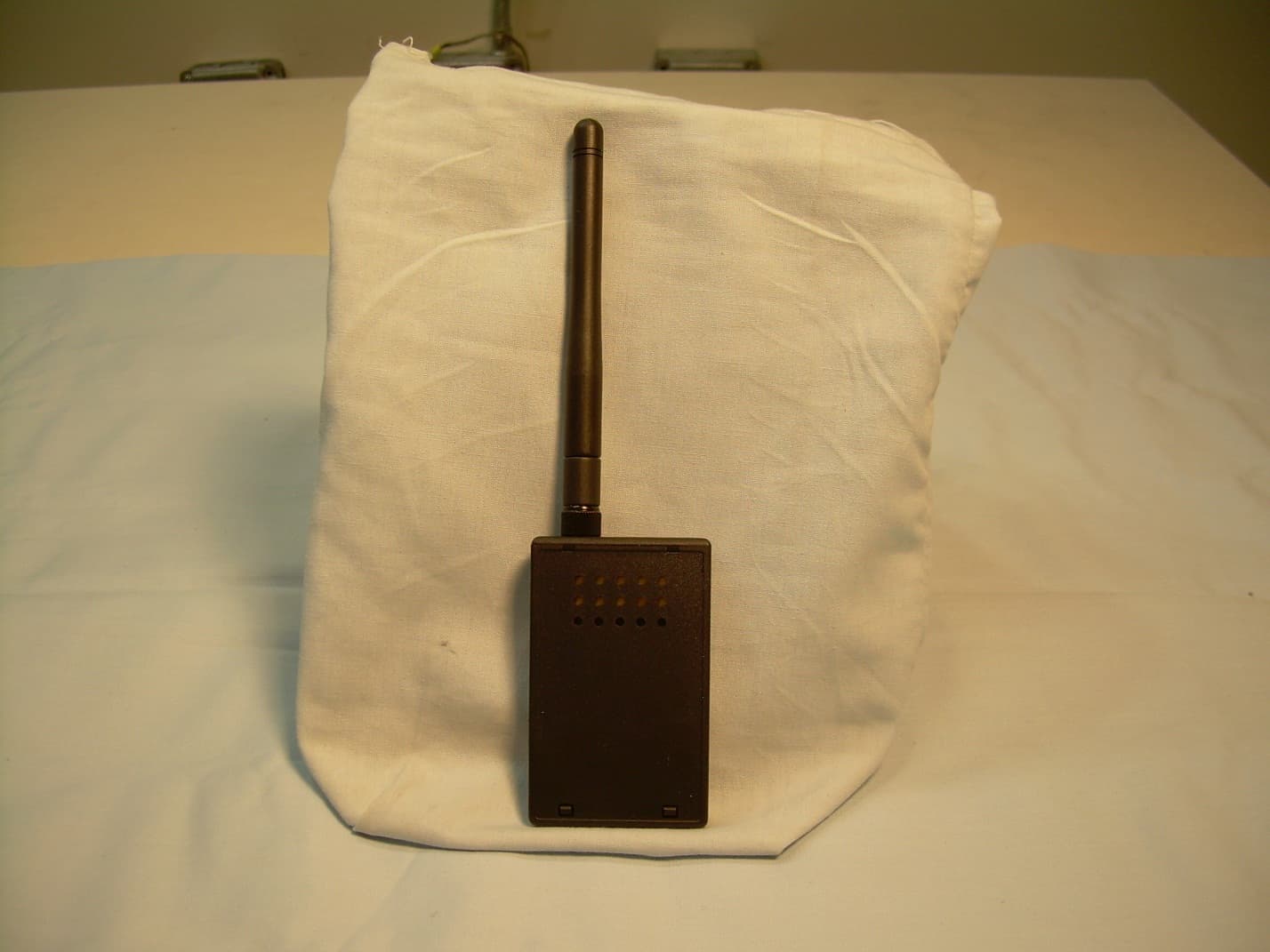
Click to zoom
Application Details
- Equipment Class
- DTS - Digital Transmission System
- Date of Grant
- Feb 12, 2014
- Application Purpose
- Original Equipment
- Date of Application
- Feb 11, 2014
- Equipment Note
- ZigBee Extender
- Frequency Range
- 2405.00000000 - 2475.00000000
- Company
- Card Access Inc
- Country
- United States
Documents & Files
Document Text
Text extracted from the exhibit documents filed with the FCC. Open a document above to read the original.
Users Manual
ZigBee Extender 3 Features The Card Access ZigBee Extender 3 operates as a ZigBee® (IEEE 802.15.4) router and mesh extender. The Extender is designed to improve ZigBee signal latency that can occur when ZigBee devices are installed on the fringes of a ZigBee mesh network. The Extender is also used to extend the ZigBee network into distant or hard-to-reach areas. The ZigBee Extender 3 works with your Control4® system and should be located within 500 feet of another routing node. For optimal results, the Extender should be located in areas of the project where the mesh may be weak or non-existent. The Extender should not be placed next to a Home Controller. Supported Models and Requirements This documentation applies to the following Card Access products: ZXT30 ZigBee Extender 3 Requires a Control4 Home Controller with Composer 2.0 or higher. Important Safety Instructions WARNING! You should install this device in accordance with all national and local electrical codes. IMPORTANT! This product is not intended for direct connections to AC mains (120V/220V). Refer to specifications. IMPORTANT! Improper use or installation of this device can result in LOSS OF/DAMAGE TO PROPERTY. IMPORTANT! Using this product in any manner other than outlined in this document voids your warranty. Also, Card Access is NOT responsible or otherwise liable in any way for any damage resulting from the misuse of this product. See the section of this document entitled WARRANTY for details. What Is Included: One (1) ZigBee Extender 3 device One (1) North American 5V DC power supply One (1) wall mounting Velcro strip One (1) Button Press Guide/LED Color Code instruction card Specifications Power Source: 5VDC Power Supply Power Usage: 65 mA at 5V Device Temperature Range: Operational -20°F to 158°F (-28°C to 70°C) Humidity 5% to 95% Non-Condensing Storage -20°F to 158°F (-28°C to 70°C) Dimensions (LxWxD): 2.80”(L) x 1.75”(W) x 0.57(D)” (77.1mm x 44.5mm x 14.4mm) The ZigBee Extender 3 is NOT waterproof and must be kept out of direct contact with water. The product must NOT be immersed. Communications: ZigBee (IEEE 802.15.4) 2.4 GHz, 15-channel, spread spectrum radio Installation 1. Place the Extender in a location that ensures: •Easy access to an outlet •ZigBee mesh networking efficiency NOTE: Make sure the Extender gets good ZigBee wireless reception by: •Ensuring it is within 500 feet of another ZigBee device. •Ensuring the device is not installed by other electrical equipment that may cause interference with the ZigBee signal (such as some cordless telephones or other devices that operate on the 2.4 GHz frequency). •Avoiding exposure to extreme environmental conditions. 2. Add the driver to your project by searching the Composer Online Driver Database. Search Device Type “other” Manufacturer “Card Access” a. If you’d prefer, you can download the ZigBee Extender 3 DriverWorks Driver from the Card Access web site: www.cardaccess-inc.com/automation/drivers. Copy the Driver to the "Control4 / Drivers" folder on your PC. (The Control4 Drivers folder should be located under "My Documents" on your PC.) b. Launch Composer. If Composer is already running, shut it down and restart it. c. Using Composer, make a connectioOnn to Director. Select the System Design Tab to add the ZigBee Extender 3 Driver. The Driver is found by selecting the Search Tab and then the Local Database. The device type is "other" and the manufacturer is Card Access. 3. Power up the Extender using the supplied 5V Power Supply. In Composer, choose Connections and click the Network Tab. Next click on the unidentified "Card Access ZigBee Extender 3" device. Identify the Extender in Composer by pressing the clear identification button on the top of the Module four (4) times. The LED should start flashing yellow. Once the Extender is identified in the system, the LED will turn solid blue. If identification fails the LED will blink green several times and go back to solid green. 4. Once the Extender's MAC ID address appears in the Identify dialog box, click "Close" to close the dialog box. 5. After a few seconds, the Extender's LED should change to a solid BLUE color, indicating it is successfully identified in the Control4 project. Troubleshooting Button Press Guide 4 button presses to identify and join ZigBee network. 9 button presses to reset to factory defaults. 13 button presses to remove it from the network. 15 button presses to reboot. LED Color Codes. Button will be: GREEN when unprovisioned. YELLOW when scanning for a network. RED when it can’t find a network. BLUE when it joins the network. Card Access Product Support: For help on the installation or operation of this product, email or call Card Access Product Support. Please provide your exact model number and the MAC ID/Serial Number for the device. You may contact Product Support by phone (801-748-4900 x 2), by e-mail ([email protected]) or on the Internet at http://www.cardaccess-inc.com/automation/support. Regulatory Compliance The Card Access ZigBee Extender 3 complies with relevant standards established by the following regulatory bodies: Federal Communications Commission (FCC), Conformité Européene (CE), and Restriction of Hazardous Substances (RoHS). FCC FCC ID: MHIZXT This device complies with Part 15 of the FCC Rules. Operation is subject to the following two conditions: (1) this device may not cause harmful interference, and (2) this device must accept any interference received, including interference that may cause undesired operation. This equipment has been tested and found to comply with the limits for a Class B digital device, pursuant to Part 15 of the FCC Rules. These limits are designed to provide reasonable protection against harmful interference in a residential installation. This equipment generates, uses, and can radiate radio frequency energy and, if not installed and used in accordance with the instructions, may cause harmful interference to radio commun…
Text truncated - open the document above for the full version.
External Photos
Front View of the EUT Back View of the EUT
ID Label/Location Info
Label placement on lower back of unit
Internal Photos
View of the Component Side of the PCB View of the Trace Side of the PCB
RF Exposure Info
Maximum Permissible Exposure Calculation The Zigbee Extender, model number ZXT30, has an RF power into the antenna of 16.27 dBm or 42.4 mW. The antenna gain is 2.0 dBi. The unit is designed to be mounted in a fixed position on a wall or door of a house and therefore the distance from the antenna to any person will typically be greater than 1 meter. The power density for continuous transmit would be calculated as: (42.4mW) (2.0) = 0.675 μW/cm 2 4π(100cm) 2 The limit for general population uncontrolled exposure at 2.4GHz is 1 mW/cm 2 . The exposure limit is also time-averaged. This device transmits in short bursts of typically 200mS or less, with several seconds between transmissions (possibly several minutes). Time-averaged over 30 minutes, the exposure is much less than continuous transmit.
Test Report
Nemko-CCL, Inc. 1940 West Alexander Street Salt Lake City, UT 84119 801-972-6146 Test Report Certification Test Of: ZXT30 FCC ID: MHIZXT Test Specifications: FCC PART 15, Subpart C Test Report Serial No: 248530-3.1 Applicant: Card Access Inc. 11778 South Election Road, Suite 260 Salt Lake City, UT 84020 U.S.A Dates of Test: November 19 and 20, 2013 Report Issue Date: December 2, 2013 Accredited Testing Laboratory By: NVLAP Lab Code 100272-0 Nemko-CCL, Inc. TEST REPORT: 248530-3.1 REPORT ISSUE DATE: 12/02/2013 Page 2 of 52 TRF-15.247 DTS SUBC Issue 1 Sep 2013 CERTIFICATION OF ENGINEERING REPORT This report has been prepared by Nemko-CCL, Inc. to document compliance of the device described below with the requirements of Federal Communications Commission (FCC) Part 15, Subpart C. This report may be reproduced in full, partial reproduction may only be made with the written consent of the laboratory. The results in this report apply only to the sample tested. - Applicant: Card Access Inc. - Manufacturer: Card Access Inc. - Brand Name: Card Access - Model Number: ZXT30 - FCC ID: MHIZXT On this 2 nd day of December 2013, I, individually and for Nemko-CCL, Inc., certify that the statements made in this engineering report are true, complete, and correct to the best of my knowledge, and are made in good faith. Although NVLAP has recognized that the Nemko-CCL, Inc. EMC testing facilities are in good standing, this report must not be used to claim product certification, approval, or endorsement by NVLAP, NIST, or any agency of the federal government. Nemko-CCL, Inc. Tested by: Norman P. Hansen Test Technician Reviewed by: Thomas C. Jackson General Manager Nemko-CCL, Inc. TEST REPORT: 248530-3.1 REPORT ISSUE DATE: 12/02/2013 Page 3 of 52 TRF-15.247 DTS SUBC Issue 1 Sep 2013 TABLE OF CONTENTS PAGE SECTION 1.0 CLIENT INFORMATION .................................................................................4 SECTION 2.0 EQUIPMENT UNDER TEST (EUT)..................................................................5 SECTION 3.0 TEST SPECIFICATION, METHODS & PROCEDURES .............................7 SECTION 4.0 OPERATION OF EUT DURING TESTING..................................................13 SECTION 5.0 SUMMARY OF TEST RESULTS ...................................................................14 SECTION 6.0 MEASUREMENTS AND RESULTS ...............................................................15 APPENDIX 1 TEST PROCEDURES AND TEST EQUIPMENT .........................................36 APPENDIX 2 PHOTOGRAPHS ................................................................................................42 APPENDIX 3 TRANSMITTER DUTY CYCLE CALCULATIONS.....................................52 Nemko-CCL, Inc. TEST REPORT: 248530-3.1 REPORT ISSUE DATE: 12/02/2013 Page 4 of 52 TRF-15.247 DTS SUBC Issue 1 Sep 2013 SECTION 1.0 CLIENT INFORMATION 1.1 Applicant: Company Name: Card Access Inc. 11778 South Election Road, Suite 260 Salt Lake City, UT 84020 U.S.A. Contact Name: James A. Stout Title: Vice President Engineering 1.2 Manufacturer: Company Name: Card Access Inc. 11778 South Election Road, Suite 260 Salt Lake City, UT 84020 U.S.A. Contact Name: James A. Stout Title: Vice President Engineering Nemko-CCL, Inc. TEST REPORT: 248530-3.1 REPORT ISSUE DATE: 12/02/2013 Page 5 of 52 TRF-15.247 DTS SUBC Issue 1 Sep 2013 SECTION 2.0 EQUIPMENT UNDER TEST (EUT) 2.1 Identification of EUT: Brand Name: Card Access Model Number: ZXT30 Serial Number: None Dimensions: 7 cm x 4.5 cm x 1.5 cm without antenna 2.2 Description of EUT: The ZXT30 is a transceiver designed to extend the Zigbee network range in Control4 home control systems. The ZXT30 is powered by a Phihong PSM03A-050, 5 V power supply. The antenna used is a Pulse W1030 dipole with a maximum gain of 2.0 dBi. The transceiver used 15 channels in the 2400 MHz – 2483.5 MHz frequency range. A list of the channel assignments is shown in the table below. Channel Frequency (MHz) Channel Frequency (MHz) Channel Frequency (MHz) Channel Frequency (MHz) 11 2405 15 2425 19 2445 23 2465 12 2410 16 2430 20 2450 24 2470 13 2415 17 2435 21 2455 25 2475 14 2420 18 2440 22 2460 This report covers the circuitry of the devices subject to FCC Part 15, Subpart C. The circuitry of the device subject to FCC Subpart B was found to be compliant and is covered in Nemko-CCL, Inc. report 248530-2. 2.3 EUT and Support Equipment: The FCC ID numbers for all the EUT and support equipment used during the test are listed below: Brand Name Model Number Serial Number FCC ID Number or Compliance Description Name of Interface Ports / Interface Cables BN: Card Access MN: ZXT30 (Note 1) SN: None MHIZXT Zigbee range extender See Section 2.4 Note: (1) EUT Nemko-CCL, Inc. TEST REPORT: 248530-3.1 REPORT ISSUE DATE: 12/02/2013 Page 6 of 52 TRF-15.247 DTS SUBC Issue 1 Sep 2013 2.4 Interface Ports on EUT: There are no interface ports on the EUT. 2.5 Modification Incorporated/Special Accessories on EUT: The following modifications were made to the EUT by the Client during testing to comply with the specification. This report is not complete without an accompanying signed attestation, that the product will have all of the documented modifications incorporated into the product when manufactured and placed on the market. 1. The maximum power setting to be incorporated in the EUT firmware was set to –5 for channels 11 – 24 and -7 for channel 25. The –7 power setting at channel 25 was required to meet the emissions in the restricted bands limit of §15.209 at 2483.5 MHz. The emissions and band edge were found compliant at channel 24 with the power setting of –5. Nemko-CCL, Inc. TEST REPORT: 248530-3.1 REPORT ISSUE DATE: 12/02/2013 Page 7 of 52 TRF-15.247 DTS SUBC Issue 1 Sep 2013 SECTION 3.0 TEST SPECIFICATION, METHODS & PROCEDURES 3.1 Test Specification: Title: FCC PART 15, Subpart C (47 CFR 15) 15.203, 15.207, and 15.247 Limits and methods of measurement of radio interference characteristics of radio frequency devices. …
Text truncated - open the document above for the full version.
Test Setup Photos
Front View Radiated Disturbance Worst Case Configuration – Vertical Back View Radiated Disturbance Worst Case Configuration – Vertical Back View Radiated Disturbance – Horizontal Configuration Back View Radiated Disturbance – On Edge Configuration Front View Conducted Disturbance Worst Case Configuration Back View Conducted Disturbance Worst Case Configuration
Contact Information
Applicant
James A Stout(Vice President Engineering)
Test Firm
Nemko-CCL, IncThomas Jackson
Technical Specifications
| # | Rule Parts | Frequency Range | Power Output |
|---|---|---|---|
| 1 | 15C | 2.40 GHz - 2.48 GHz | 42.40 mW |
Other Applications from Card Access Inc
MHIFYX-1
May 11, 2013WLAN 802.11bgn 2.4GHz 1x1 and BLE v4.0 Bridge
Equipment Class
DTS - Digital Transmission System
MHISUB10A
Feb 29, 2012Home Automation Appliance
Equipment Class
DTS - Digital Transmission System
MHIZGB20
Jan 06, 2011Card Access Security Sensor Bridge V2
Equipment Class
DTS - Digital Transmission System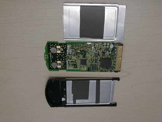
MHI-CAWCB500
Oct 14, 20015.15 - 5.35 GHz UNII CardBusTransceiver model CAWC
Equipment Class
NII - Unlicensed National Information Infrastructure TXMHI751001
Nov 01, 1995PCMCIA Serial Interface Card
Equipment Class
JBP - Part 15 Class B Computing Device Peripheral