MHIZGB20Card Access Security Sensor Bridge V2
Card Access Inc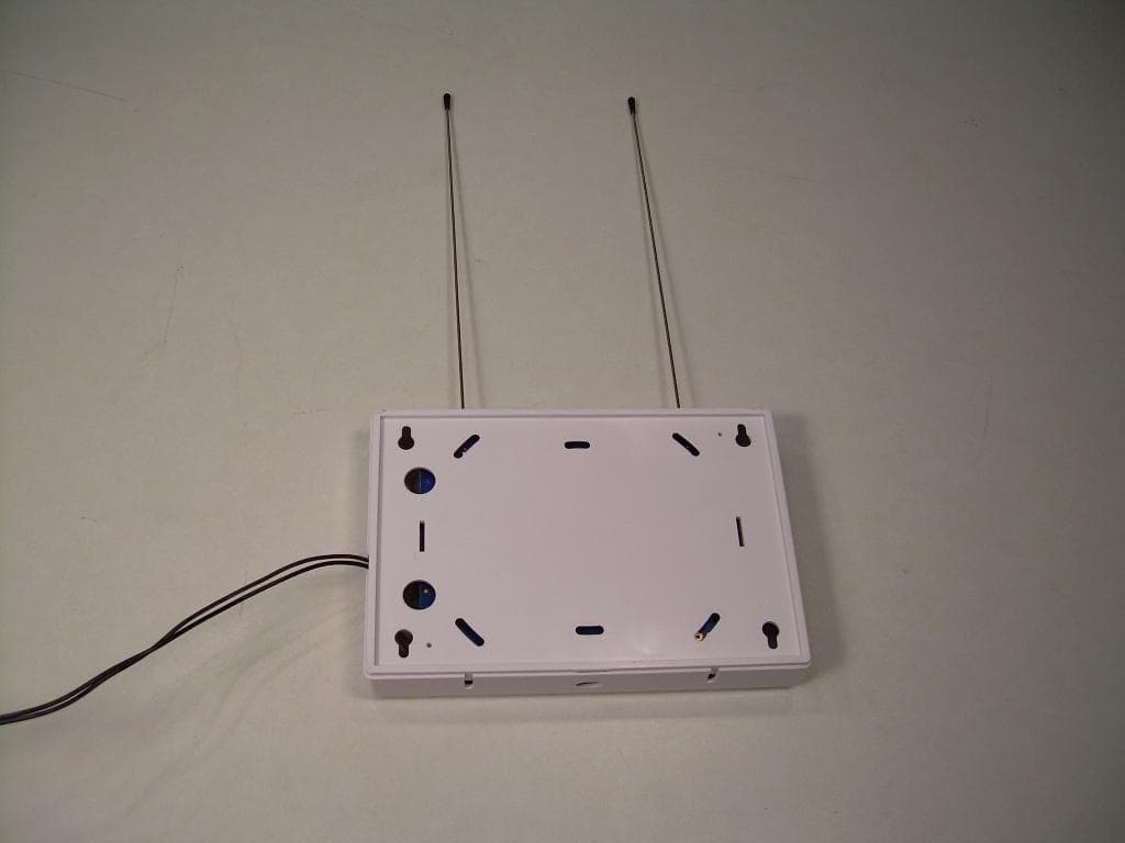
Click to zoom
Application Details
- Equipment Class
- DTS - Digital Transmission System
- Date of Grant
- Jan 06, 2011
- Application Purpose
- Original Equipment
- Date of Application
- Jan 06, 2011
- Equipment Note
- Card Access Security Sensor Bridge V2
- Frequency Range
- 2405.00000000 - 2475.00000000
- Company
- Card Access Inc
- Country
- United States
Documents & Files
Document Text
Text extracted from the exhibit documents filed with the FCC. Open a document above to read the original.
Users Manual
_________________________________________________________________________________________________________________________ Card Access Security Sensor Bridge V2 Page 1 of 12 Quick Start & Installation Guide Card Access, Inc. Security Sensor Bridge V2 Model Number: ZGB20 Quick Start and Installation Guide Card Access Security Sensor Bridge Quick Start and Installation Guide Easily bridge inexpensive security sensors into home automation -- with or without a security panel* _________________________________________________________________________________________________________________________ Card Access Security Sensor Bridge V2 Page 2 of 12 Quick Start & Installation Guide Card Access, Inc. Welcome and congratulations on your purchase of the Card Access Security Sensor Bridge. This Quick Start & Installation Guide is an overview of configuring your Security Sensor Bridge with a Control4 System. This guide assumes that you are a qualified and trained Control4 dealer. *NOTICE: THE SECURITY SENSOR BRIDGE V2 IS INTENDED FOR HOME AUTOMATION PURPOSES ONLY. THIS IS NOT A SECURITY SYSTEM. Introduction The Card Access Security Sensor Bridge is a device capable of receiving and interpreting signals from GE/ITI sensors and integrating these signals with a Control4 System via the Control4 ZigBee wireless mesh. This device gives the homeowner the ability to utilize the wide range of GE sensors available as accessories to the Control4 system. The device consists of a self-contained, wall-mountable bridge in a plastic enclosure. It is powered by a 12V DC adapter. Specifications ZGB20 Specifications Dimensions 6.75” x 4.5” x 1.5” (excluding antennas) Weight 0.5 Lbs (0.23Kg) Maximum Ambient Operational Temperature 140°F (60°C) Power Input 12VDC, 100mA Operational Environment Type 1 Device shall be mounted in a dry, moisture-protected location. Site Requirements and Wiring Options • Allow at least 10 inches of clearance above the enclosure for the antennas. • Avoid mounting locations that expose the module to moisture. • Avoid areas with excessive metal or electrical wiring including furnace and utility rooms. If unavoidable, mount on or near metal with the antenna extending above the metallic surfaces as shown in Figure 1. • Ensure that an electrical source is accessible for the DC power adaptor. Figure 1 - Mounting on or near metal Tools and Supplies Needed To complete the installation, you will need the following tools and supplies: • Screwdrivers _________________________________________________________________________________________________________________________ Card Access Security Sensor Bridge V2 Page 3 of 12 Quick Start & Installation Guide Card Access, Inc. • Drill with bits • Mounting screws and anchors (included) Mounting The bridge can be mounted on any interior wall (protected from the elements) by following these steps: 1. Remove the cover by pressing in the button on the bottom of the enclosure and rocking the cover outward. 2. Hold the bridge base against the mounting surface and mark the four (4) mounting holes and two (2) wire access holes as shown in Figure 2. Remember to leave at least 10 in. (25 cm) above the bridge for the antennas. NOTE: The circuit board may be hinged out of the bridge base plastics to gain better access to the mounting holes by pulling outward on the retaining latch with a finger. 3. Drill holes and insert the appropriate anchors. 4. Use the wire access holes to route the wires from the DC power supply (included) into the bridge base. 5. Secure the bridge base to the wall with the pan head screws provided. Figure 2 – Bridge Base Plastics Wiring To wire the DC power supply to the bridge, do the following: 1. Remove AC power (if applied) to the included DC power supply. 2. Wire leads of DC power supply into terminal block on the lower right side of the board. Polarity of the wires does not matter. 3. Install metal antennas into outer slots of terminal blocks at top of board. 4. Replace cover. Control4 Software Installation / Operation Instructions NOTE: The Card Access Security Sensor Bridge and GE Sensors use Control4 DriverWorks™ drivers, which are not included with Composer software. They must be downloaded from the Card Access website and manually installed. Download and Install Drivers: 1. Go to http://www.cardaccess-inc.com/automation/drivers 2. Download the drivers you will need to use in your project. 3. Copy them to the appropriate folder on the computer you will be using to configure the project, typically “My Documents\control4\Drivers\” _________________________________________________________________________________________________________________________ Card Access Security Sensor Bridge V2 Page 4 of 12 Quick Start & Installation Guide Card Access, Inc. Add the Security Sensor Bridge V2 (ZGB20) to your Composer project: 1. In System Design view in Composer, select the ‘Card Access ZGB20’ driver from the Search tab and drag it into your project (see figure at right). 2. Identification is similar to other Control4 ZigBee devices: Go to Connections view in Composer and choose the ‘Network’ tab. Find the Card Access Security Sensor Bridge device in the device list and highlight it. Then click the ‘Identify’ button at the top of the screen. 3. When prompted to identify the unit, press the ID button on the Bridge by using a paper clip inserted through the small hole located on the face of the Bridge. Press the button four times in succession. The ‘BUS’ LED on the Security Sensor Bridge will begin blinking as it attempts to join the ZigBee mesh and identify into the Control4 project. 4. When the Security Sensor Bridge has successfully joined the ZigBee mesh and identified, the address of the bridge will appear in the identification window. Click the ‘Close’ button. To add additional Security Sensor Bridges to your Composer project: 1. When using two or more Security Sensor Bridges in the project, you must first add one ZGB20 driver for the first Security…
Text truncated - open the document above for the full version.
External Photos
Front View of the EUT Back View of the EUT
Internal Photos
View of the Component Side of the PCB View of the Trace Side of the PCB
Test Report
Nemko-CCL, Inc. 1940 West Alexander Street Salt Lake City, UT 84119 801-972-6146 Test Report Certification Test Of: ZGB20 FCC ID: MHIZGB20 Test Specification: FCC PART 15, Subpart C Test Report Serial No: 161048-2.1 Applicant: Card Access Inc. 11778 South Election Road, Suite 260 Salt Lake City, UT 84020 Date of Test: November 1, 2010 Issue Date: November 16, 2010 Accredited Testing Laboratory By: NVLAP Lab Code 100272-0 Nemko-CCL, Inc. TEST REPORT: 161048-2.1 FCC ID#: MHIZGB20 Page 2 of 46 2 CERTIFICATION OF ENGINEERING REPORT This report has been prepared by Nemko-CCL, Inc. to document compliance of the device described below with the requirements of Federal Communications Commission (FCC) Part 15, Subpart C. This report may be reproduced in full, partial reproduction may only be made with the written consent of the laboratory. The results in this report apply only to the sample tested. - Applicant: Card Access Inc. - Manufacturer: Card Access Inc. - Brand Name: Card Access Security Sensor Bridge V2 - Model Number: ZGB20 - FCC ID Number: MHIZGB20 On this 16 th day of November 2010, I, individually, and for Nemko-CCL, Inc., certify that the statements made in this engineering report are true, complete, and correct to the best of my knowledge, and are made in good faith. Although NVLAP has recognized that the Nemko-CCL, Inc. EMC testing facilities are in good standing, this report must not be used to claim product certification, approval, or endorsement by NVLAP, NIST, or any agency of the federal government. Nemko-CCL, Inc. Tested by: Norman P. Hansen EMC Technician Nemko-CCL, Inc. TEST REPORT: 161048-2.1 FCC ID#: MHIZGB20 Page 3 of 46 3 TABLE OF CONTENTS PAGE SECTION 1.0 CLIENT INFORMATION .................................................................................4 SECTION 2.0 EQUIPMENT UNDER TEST (EUT) .................................................................5 SECTION 3.0 TEST SPECIFICATION, METHODS & PROCEDURES .............................8 SECTION 4.0 OPERATION OF EUT DURING TESTING ..................................................14 SECTION 5.0 SUMMARY OF TEST RESULTS ...................................................................15 SECTION 6.0 MEASUREMENTS, EXAMINATIONS AND DERIVED RESULTS ..........16 APPENDIX 1 TEST PROCEDURES AND TEST EQUIPMENT ..........................................29 APPENDIX 2 PHOTOGRAPHS ................................................................................................37 APPENDIX 3 MANUFACTURER’S STATEMENT/ATTESTATION .................................46 Nemko-CCL, Inc. TEST REPORT: 161048-2.1 FCC ID#: MHIZGB20 Page 4 of 46 4 SECTION 1.0 CLIENT INFORMATION 1.1 Applicant: Company Name: Card Access Inc. 11778 South Election Road, Suite 260 Salt Lake City, UT 84020 Contact Name: James Stout Title: Vice President Engineering 1.2 Manufacturer: Company Name: Card Access Inc. 11778 South Election Road, Suite 260 Salt Lake City, UT 84020 Contact Name: James Stout Title: Vice President Engineering Nemko-CCL, Inc. TEST REPORT: 161048-2.1 FCC ID#: MHIZGB20 Page 5 of 46 5 SECTION 2.0 EQUIPMENT UNDER TEST (EUT) 2.1 Identification of EUT: Brand Name: Card Access Security Sensor Bridge V2 Model Number: ZGB20 Serial Number: None 2.2 Description of EUT: The ZGB20 is a sensor bridge to the Zigbee network. Signals from sensors operating at 433.92 MHz or 319.5 MHz are received and then transmitted over a Zigbee network. The ZGB20 contains a receiver, operating at either 319.5 MHz or 433.92 MHz, and a Zigbee transceiver operating in the 2400 – 2483.5 MHz band. The ZGB20 is powered from a Shen Zhen Jodeway Electron Co. Ltd. JOD-S-120050A, 12 Vdc power supply. . The ZGB20 uses 15 channels in the 2400 to 2483.5 MHz frequency range. The antenna is a trace on the PCB. See the plots below. dBm 0 -10 -20 -30 -40 -50 -60 -70 -80 -90 -100 T race A Start: 2.402500 GHzStop: 2.427500 GHz T race ALower 5 channels 1 1 2.405000 GHz -5.4000 dBm 2 2 2.410075 GHz -5.1000 dBm 3 3 2.415075 GHz -5.8000 dBm 4 4 2.420050 GHz -5.8000 dBm 5 5 2.425025 GHz -5.8000 dBm Nemko-CCL, Inc. TEST REPORT: 161048-2.1 FCC ID#: MHIZGB20 Page 6 of 46 6 dBm 0 -10 -20 -30 -40 -50 -60 -70 -80 -90 -100 T race A Start: 2.427500 GHzStop: 2.452500 GHz T race AMiddle 5 channels 11 2.430000 GHz -6.5000 dBm 2 2 2.435075 GHz -5.5000 dBm 3 3 2.440075 GHz -6.2000 dBm 4 4 2.445050 GHz -6.1000 dBm 5 5 2.450025 GHz -5.3000 dBm dBm 0 -10 -20 -30 -40 -50 -60 -70 -80 -90 -100 T race A Start: 2.452500 GHzStop: 2.477500 GHz T race AUpper 5 channels 1 1 2.455000 GHz -7.4000 dBm 2 2 2.460075 GHz -8.1000 dBm 3 3 2.465075 GHz -8.2000 dBm 4 4 2.470050 GHz -7.6000 dBm 5 5 2.475025 GHz -7.5000 dBm This report covers the circuitry of the devices subject to FCC Part 15, Subpart C. The circuitry of the device subject to FCC Part 15, Subpart B is covered in Nemko-CCL, Inc. report #161048-1.1. Nemko-CCL, Inc. TEST REPORT: 161048-2.1 FCC ID#: MHIZGB20 Page 7 of 46 7 2.3 EUT and Support Equipment: The FCC ID numbers for all the EUT and support equipment used during the test are listed below: Brand Name Model Number Serial Number FCC ID Number or Compliance Description Name of Interface Ports / Interface Cables BN: Card Access MN: ZGB20 SN: None MHIZGB20 Sensor Bridge See Section 2.4 2.4 Interface Ports on EUT: There are no interface ports on the EUT. 2.5 Modification Incorporated/Special Accessories on EUT: There were no modifications or special accessories required to comply with the specification. This report is not complete without an accompanying signed attestation, included as Appendix 3, that the product will have all of the documented modifications incorporated into the product when manufactured and placed on the market. Nemko-CCL, Inc. TEST REPORT: 161048-2.1 FCC ID#: MHIZGB20 Page 8 of 46 8 SECTION 3.0 TEST SPECIFICATION, METHODS & PROCEDURES 3.1 Test Specification: Title: FCC PART 15, Subpart C (47 CFR 15) 15.203, 15.207, and 15.247 Limits and methods of measurement of radio interference characteristics o…
Text truncated - open the document above for the full version.
Test Setup Photos
Front View Radiated Disturbance Worst Case Configuration Back View Radiated Disturbance Worst Case Configuration Front View Conducted Disturbance Worst Case Configuration Back View Conducted Disturbance Worst Case Configuration
Contact Information
Applicant
James A Stout(Vice President Engineering)
Test Firm
VPI TechnologyJason Stewart
[email protected]801-495-2310
Technical Specifications
| # | Rule Parts | Frequency Range | Power Output |
|---|---|---|---|
| 1 | 15C | 2.40 GHz - 2.48 GHz | 4.57 mW |
Other Applications from Card Access Inc
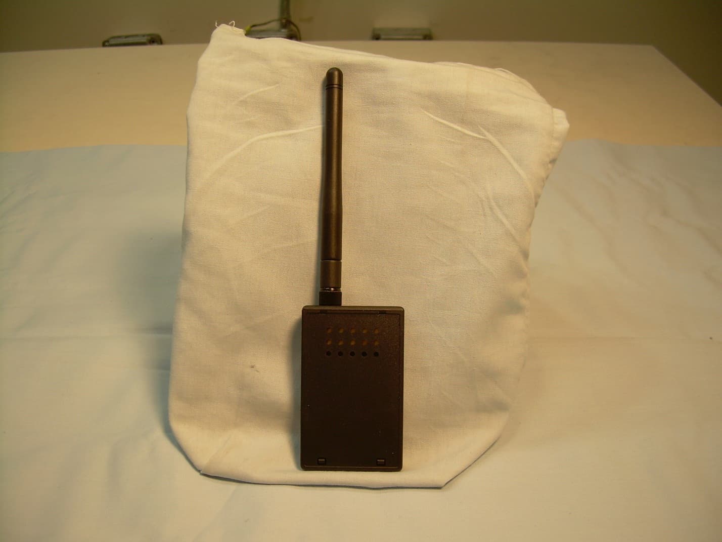
MHIZXT
Feb 12, 2014ZigBee Extender
Equipment Class
DTS - Digital Transmission System
MHIFYX-1
May 11, 2013WLAN 802.11bgn 2.4GHz 1x1 and BLE v4.0 Bridge
Equipment Class
DTS - Digital Transmission System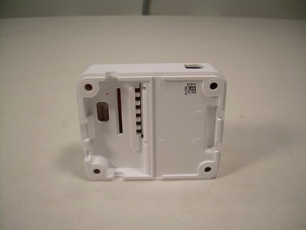
MHISUB10A
Feb 29, 2012Home Automation Appliance
Equipment Class
DTS - Digital Transmission System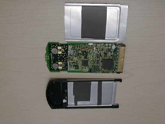
MHI-CAWCB500
Oct 14, 20015.15 - 5.35 GHz UNII CardBusTransceiver model CAWC
Equipment Class
NII - Unlicensed National Information Infrastructure TXMHI751001
Nov 01, 1995PCMCIA Serial Interface Card
Equipment Class
JBP - Part 15 Class B Computing Device Peripheral