MI7-ECSHPA80TXRF Amplifier
IP Mobilenet, LLC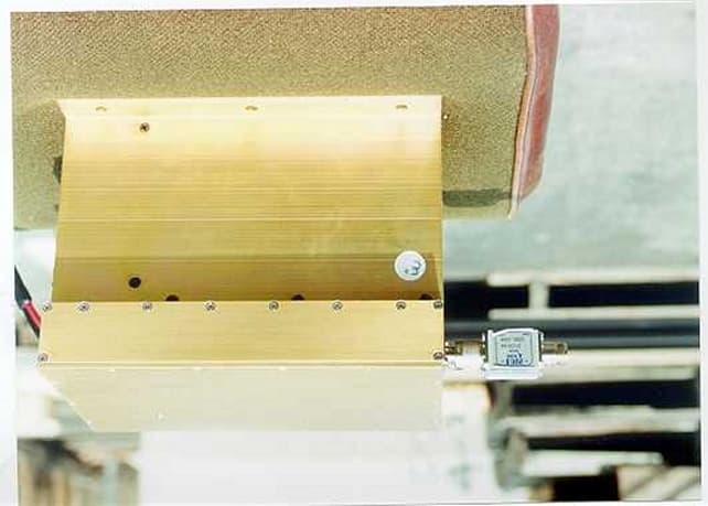
Click to zoom
Application Details
- Equipment Class
- AMP - Amplifier
- Date of Grant
- May 08, 2001
- Application Purpose
- Original Equipment
- Date of Application
- Mar 21, 2001
- Equipment Note
- RF Amplifier
- Frequency Range
- 851.00000000 - 866.00000000
- Company
- IP Mobilenet, LLC
- Country
- United States
Documents & Files
Document Text
Text extracted from the exhibit documents filed with the FCC. Open a document above to read the original.
Users Manual
FCC ID: MI7-ECSHPA80TX A1 A A p p p p e e n n d d i i x x A A FCC ID: MI7-ECSHPA80TX A2 E E L L E E C C T T R R O O C C O O M M I I N N V V A A D D R R t t m m M M O O B B I I L L E E D D A A T T A A A A N N D D V V O O I I C C E E S S Y Y S S T T E E M M C C O O M M P P O O N N E E N N T T HPA8 800 MHZ HIGH POWER AMPLIFIER PRODUCT SUPPORT MANUAL Document Number 516-80075 Revision X2 11909 East Telegraph Road, Santa Fe Springs, CA 90670-3785 Voice: (562) 946-9493 Fax: (562) 949-0223 FCC ID: MI7-ECSHPA80TX Ai NOTICES INVADR tm is a registered trademark of ElectroCom Systems, Inc. Contents copyrighted 2001 by ElectroCom Systems, Inc. All rights reserved. FCC ID: MI7-ECSHPA80TX Aii CONTENTS 1. Introduction .................................................................................... 1 1.1 Scope ...................................................................................... 1 1.2 Reference Materials ................................................................ 2 1.2.1 ElectroCom Documents ............................................... 2 1.3 Product Description ................................................................ 3 1.4 Product Features ..................................................................... 3 2. Interface Description ..................................................................... 4 3. Installation ..................................................................................... 4 3.1 Unpacking ............................................................................... 4 3.2 Installation .............................................................................. 5 3.2.1 Typical Rack Installation .............................................. 5 3.2.2 Installation Instructions ................................................ 5 4. Theory of Operation ...................................................................... 6 4.1 Thermal Equilibration System ............................................... 6 4.2 RF Amplifier Section ............................................................. 7 5. Maintenance .................................................................................. 9 6. Specifications ................................................................................ 9 7. Warranty and Service .................................................................... 10 7.1 Warranty ................................................................................. 10 7.2 Warranty/Non-Warranty Service ............................................ 10 8. Diagrams and Lists ........................................................................ 11 8.1 Block Diagram 8.2 Schematic Diagram 8.3 Interconnection Diagram 8.4 Board Parts List FCC ID: MI7-ECSHPA80TX A1 1. Introduction 1.1 Scope This document describes the hardware of the HPA8 High Power Amplifier as follows: Section 1: Overview of the unit and its features. Section 2: Interfaces (e.g. connectors, power sources, etc.). Section 3: Installation procedure. Section 4: Circuit theory. Section 5: Maintenance procedures. Section 6: Specifications. Section 7: Warranty and warranty/non-warranty service information. Section 8: Diagrams and lists. FCC ID: MI7-ECSHPA80TX A2 1.2 Reference Materials 1.2.1 ElectroCom Documents (attached) The following ElectroCom documents are provided as attachments to Section 8: NUMBERDOCUMENT NO.DESCRIPTION 1HPA8Block Diagram 2502-80228Interconnection Diagram 3502-80228Schematic Diagram 4502-80292PWA Parts List FCC ID: MI7-ECSHPA80TX A3 1.3 Product Description The ElectroCom HPA8 High Power Amplifier was designed specifically to operate with the ElectroCom IP8B Base Station Data Transceiver. Basically, the unit amplifies the RF output of the IP8B, providing up to 80 watts of RF power for the antenna system. The HPA8 is intended for base station use only. For enhanced reliability, the HPA8 incorporates a four power amplifier module design which permits “graceful” degradation of output power under fault conditions. This means the unit will continue to operate (albeit at gradually reduced power levels) despite failures in up to three power amplifier modules. The useful life of the HPA8 is extended by a 3-stage thermal “equilibration” scheme. “Equilibration” refers to the act of equalizing the operating temperatures of the four power amplifier modules. By doing so, and by keeping the temperature within reasonable limits, heat stress on the modules is minimized. This results in longer operating life for the modules, and increased overall reliability for the HPA8. The HPA8 is equipped with over-temperature and over-voltage protection. To prevent damage from excessive heat, or from a defective power supply, the cabinet temperature and power supply voltage is monitored at all times. 1.4 Product Features The HPA8 High Power Amplifier features: • 80 watts RF output (typical). • Covers 851-866 MHz • Four power amplifier module design. • Graceful degradation of power under fault conditions. • 3-stage thermal equilibration protection system. • Over-temperature protection. • Over-voltage protection. • 13.8 VDC operation. • Compact size, rugged construction. FCC ID: MI7-ECSHPA80TX A4 2. Interface Description As shown in section 8.3, the HPA8 has the following interface connections: J1 RF input. Typically connects to the IP8B Base Station Data Transceiver. J2 RF output. Typically connects to the antenna system components in the rack. WARNING! Do not remove the harmonic filter, or operate the HPA8 without the filter installed. Excessive harmonic emissions may result. J3 DC power connector. Plugs into a 13.8 volt (nominal), 25 amp (or greater) DC power supply. J4 Control interface connector. The transmit keying input connects to the IP8B Base Station Data Transceiver via an INVADR I/O Interface Board mounted on the rack. The high temperature alarm output may be connected to an alarm monitoring system, or to the ALARM connector on the INVADR I/O Interface Board. 3. Insta…
Text truncated - open the document above for the full version.
Cover Letter(s)
To whom it may concern, I recently sumitted a Form 731 with an incorrect FCC Id number Confirmation # EA100393 and FCC ID:MI7ECSHPA80TX. The correct ID number should read as follows MI7-ECSHPA80TX. Please change Form 731 so that all the paper work reflects the correct Id number. If you have any questions please contact myself or Bryan Broaddus at ([email protected]). Thank you, Fred Gurule DNB Engineering, Inc. \ [email protected]
Cover Letter(s)
To whom it may concern, I recently sumitted a Form 731 with an incorrect FCC Id number Confirmation # EA100393 and FCC ID:MI7ECSHPA80TX. The correct ID number should read as follows MI7-ECSHPA80TX. Please change Form 731 so that all the paper work reflects the correct Id number. If you have any questions please contact myself or Bryan Broaddus at ([email protected]). Thank you, Fred Gurule DNB Engineering, Inc. [email protected]
External Photos
FCC ID: MI7-ECSHPA80TX External Photos FCC ID: MI7-ECSHPA80TX
ID Label/Location Info
FCC ID: MI7-ECSHPA80TX FCC ID: LABEL NOTES: Label will be constructed of 0.02 inch aluminum as shown on the equipment with permanent adhesive. All information on the label will be etched or stamped. Both methods will exceed the expected lifetime of the equipment. The label will be large enough to allow all information to be legible.
ID Label/Location Info
FCC ID: MI7-ECSHPA80TX FCC ID: LABEL NOTES: Label will be constructed of 0.02 inch aluminum as shown on the equipment with permanent adhesive. All information on the label will be etched or stamped. Both methods will exceed the expected lifetime of the equipment. The label will be large enough to allow all information to be legible.
Internal Photos
FCC ID: MI7-ECSHPA80TX Internal Photos
Operational Description
FCC ID: MI7-ECSHPA80TX A1 A A p p p p e e n n d d i i x x A A FCC ID: MI7-ECSHPA80TX A2 E E L L E E C C T T R R O O C C O O M M I I N N V V A A D D R R t t m m M M O O B B I I L L E E D D A A T T A A A A N N D D V V O O I I C C E E S S Y Y S S T T E E M M C C O O M M P P O O N N E E N N T T HPA8 800 MHZ HIGH POWER AMPLIFIER PRODUCT SUPPORT MANUAL Document Number 516-80075 Revision X2 11909 East Telegraph Road, Santa Fe Springs, CA 90670-3785 Voice: (562) 946-9493 Fax: (562) 949-0223 FCC ID: MI7-ECSHPA80TX Ai NOTICES INVADR tm is a registered trademark of ElectroCom Systems, Inc. Contents copyrighted 2001 by ElectroCom Systems, Inc. All rights reserved. FCC ID: MI7-ECSHPA80TX Aii CONTENTS 1. Introduction .................................................................................... 1 1.1 Scope ...................................................................................... 1 1.2 Reference Materials ................................................................ 2 1.2.1 ElectroCom Documents ............................................... 2 1.3 Product Description ................................................................ 3 1.4 Product Features ..................................................................... 3 2. Interface Description ..................................................................... 4 3. Installation ..................................................................................... 4 3.1 Unpacking ............................................................................... 4 3.2 Installation .............................................................................. 5 3.2.1 Typical Rack Installation .............................................. 5 3.2.2 Installation Instructions ................................................ 5 4. Theory of Operation ...................................................................... 6 4.1 Thermal Equilibration System ............................................... 6 4.2 RF Amplifier Section ............................................................. 7 5. Maintenance .................................................................................. 9 6. Specifications ................................................................................ 9 7. Warranty and Service .................................................................... 10 7.1 Warranty ................................................................................. 10 7.2 Warranty/Non-Warranty Service ............................................ 10 8. Diagrams and Lists ........................................................................ 11 8.1 Block Diagram 8.2 Schematic Diagram 8.3 Interconnection Diagram 8.4 Board Parts List FCC ID: MI7-ECSHPA80TX A1 1. Introduction 1.1 Scope This document describes the hardware of the HPA8 High Power Amplifier as follows: Section 1: Overview of the unit and its features. Section 2: Interfaces (e.g. connectors, power sources, etc.). Section 3: Installation procedure. Section 4: Circuit theory. Section 5: Maintenance procedures. Section 6: Specifications. Section 7: Warranty and warranty/non-warranty service information. Section 8: Diagrams and lists. FCC ID: MI7-ECSHPA80TX A2 1.2 Reference Materials 1.2.1 ElectroCom Documents (attached) The following ElectroCom documents are provided as attachments to Section 8: NUMBERDOCUMENT NO.DESCRIPTION 1HPA8Block Diagram 2502-80228Interconnection Diagram 3502-80228Schematic Diagram 4502-80292PWA Parts List FCC ID: MI7-ECSHPA80TX A3 1.3 Product Description The ElectroCom HPA8 High Power Amplifier was designed specifically to operate with the ElectroCom IP8B Base Station Data Transceiver. Basically, the unit amplifies the RF output of the IP8B, providing up to 80 watts of RF power for the antenna system. The HPA8 is intended for base station use only. For enhanced reliability, the HPA8 incorporates a four power amplifier module design which permits “graceful” degradation of output power under fault conditions. This means the unit will continue to operate (albeit at gradually reduced power levels) despite failures in up to three power amplifier modules. The useful life of the HPA8 is extended by a 3-stage thermal “equilibration” scheme. “Equilibration” refers to the act of equalizing the operating temperatures of the four power amplifier modules. By doing so, and by keeping the temperature within reasonable limits, heat stress on the modules is minimized. This results in longer operating life for the modules, and increased overall reliability for the HPA8. The HPA8 is equipped with over-temperature and over-voltage protection. To prevent damage from excessive heat, or from a defective power supply, the cabinet temperature and power supply voltage is monitored at all times. 1.4 Product Features The HPA8 High Power Amplifier features: • 80 watts RF output (typical). • Covers 851-866 MHz • Four power amplifier module design. • Graceful degradation of power under fault conditions. • 3-stage thermal equilibration protection system. • Over-temperature protection. • Over-voltage protection. • 13.8 VDC operation. • Compact size, rugged construction. FCC ID: MI7-ECSHPA80TX A4 2. Interface Description As shown in section 8.3, the HPA8 has the following interface connections: J1 RF input. Typically connects to the IP8B Base Station Data Transceiver. J2 RF output. Typically connects to the antenna system components in the rack. WARNING! Do not remove the harmonic filter, or operate the HPA8 without the filter installed. Excessive harmonic emissions may result. J3 DC power connector. Plugs into a 13.8 volt (nominal), 25 amp (or greater) DC power supply. J4 Control interface connector. The transmit keying input connects to the IP8B Base Station Data Transceiver via an INVADR I/O Interface Board mounted on the rack. The high temperature alarm output may be connected to an alarm monitoring system, or to the ALARM connector on the INVADR I/O Interface Board. 3. Insta…
Text truncated - open the document above for the full version.
Parts List/Tune Up Info
FCC ID: MI7-ECSHPA80TX Parts List FCC ID: MI7-ECSHPA80TX FCC ID: MI7-ECSHPA80TX FCC ID: MI7-ECSHPA80TX
Test Report
FCC ID: MI7-ECSHPA80TX 1 Application for Certification For an RF Power Amplifier ElectroCom Systems 11909 E. Telegraph Rd. Santa Fe Springs, CA 90670-3728 RF Amplifier: Model # HPA8 FCC ID: MI7-ECSHPA80TX REPORT # RA054930/10120 This report was prepared in accordance with the requirements of the FCC Rules and Regulations Part 2, Subpart J, 2.1031 through 2.1057, Part 90 and other applicable sections of the rules as indicated herein. Prepared By: Fred Gurule DNB Engineering, Inc. 3535 W. Commonwealth Ave. Fullerton, CA 92833 4 MARCH 2001 FCC ID: MI7-ECSHPA80TX 2 TABLE OF CONTENTS Section Title Sheet # 1.0ADMINISTRATIVE DATA3 1.1Certificatio ns a nd Q ua lificatio ns3 1.2Meas ure me nts a nd Repea tab ility Info rma tio n3 Note: Paragraph numbers in this report follow the application section numbers found in the FEDERAL COMMUNICATIONS COMMISSION Rules and Regulations, Part 2, Subpart J for Certification of electronic equipment. 2.1033 (C) (1)Application for Certification4 2.1033 (C) (2)FCC Identifier4 2.1033 (C) (3)Installation and Operating Instructions4 2.1033 (C) (4)Type of Emissions4 2.1033 (C) (5)Frequency Range5 2.1033 (C) (6)Operating Power5 2.1033 (C) (7)Maximum Power Allowed in Applicable part(s) of the Rules5 2.1033 (C) (8)Final RF Amplifier Input Power C haracteristics5 2.1033 (C) (9)Tune Up Procedure5 2.1033 (C) (10)Schematic Diagram and C ircuit Description6 2.1033 (C) (11)Equipment Identification Plate6 2.1033 (C) (12) Equipment Photographs7 - 11 2.1033 (C) (13)Digital Modulation Techniques12 2.1033 (C) (14)Test Data12 2.1046Measurement of RF Power Output12 - 15 2.1049Measurement of Occupied Bandwidth16 - 20 FIGURE 1 :BLOCK DIAGRAM (Occ up ied Ba nd wid th te sts )17 2.1051Spurious Emissions at Antenna Terminals21 - 32 FIGURE 2: BLOCK DIAGRAM (Spurious Emissions tests)22 2.1053Measurement of Field Strength of Spurious Radiation33 Table 1: Field Strength of Spurious Radiation35 2.1055Measurement of Frequency Stability36 2.1057Frequency Spectrum to be Investigated36 APPENDIX AService/Operating ManualA1 - A12 APPENDIX BSchematicsB1 - B7 FCC ID: MI7-ECSHPA80TX 3 1.0ADMINISTRATIVE DATA 1.1Certifications and Qualifications I certify that DNB Engineering, Inc conducted the tests performed in order to obtain the technical data presented in this application. Also, based on the results of the enclosed data, I have concluded that the equipment tested meets or exceeds the requirements of the Rules and Regulations governing this application. 1.2Measurement Repeatability Information The test data presented in this report has been acquired using the guidelines set forth in FCC Part 2.1031 through 2.1057, Part 90. The test results presented in this document are valid only for the equipment identified herein under the test conditions described. Repeatability of these test results will only be achieved with identical measurement conditions. These conditions include: The same test distance, EUT Height, Measurement Site Characteristics, and the same EUT System Components. The system must have the same Interconnecting Cables arranged in identical placement to that in the test set-up, with the system and/or EUT functioning in the identical mode of operation (i.e. software and so on) as on the date of the test. Any deviation from the test conditions and the environment on the date of the test may result in measurement repeatability difficulties. All changes made to the EUT during the course of testing as identified in this test report must be incorporated into the EUT or identical models to ensure compliance with the FCC regulations. Bryan Broaddus (Para. 1.1) Manager, Test Dept. DNB Engineering, Inc. Tel. (714) 870-7781 FAX (714) 870-5081 FCC ID: MI7-ECSHPA80TX 4 2.1033 (C) (1)Application for Certification Name of Applicant:ElectroCom Systems 11909 E. Telegraph Rd. Santa Fe Springs, CA 90670-3728 Applicant is:XManufacturer Vendor Licensee Prospective Licensee Other Description: RF Amplifier Part Number: HPA8 Anticipated Production Quantity: Multiple Units 2.1033 (C) 2)FCC Identifier FCC ID: MI7-ECSHPA80TX 2.1033 (C) 3)Installation and Operating Instructions Please refer to Appendix A 2.1033 (C) (4)Type of Emission N/A FCC ID: MI7-ECSHPA80TX 5 2.1033 (C) (5)Frequency Range 851 - 866 MHz 2.1033 (C) 6)Operating Power 80 Watts 2.1033 (C) (7)Maximum Power Allowed in Applicable Part(s) of the Rules RULES PART MAXIMUM POWER (WATTS) Part 90.21380 2.1033 (C) (8)Final RF Amplifier Input Power Characteristics Input Voltage: 12 Vdc Nominal Input Current:15 Adc Nominal 2.1033 (C) (9) Tune Up Procedure Please refer to Appendix A. FCC ID: MI7-ECSHPA80TX 6 2.1033 (C) (10)Schematic Diagram and Circuit Description Please refer to Appendix B 2.1033 (C) (11)Equipment Identification Plate NOTES: Label will be constructed of 0.02 inch aluminum as shown on the equipment with permanent adhesive. All information on the label will be etched or stamped. Both methods will exceed the expected lifetime of the equipment. The label will be large enough to allow all information to be legible. FCC ID: MI7-ECSHPA80TX 7 FCC ID: MI7-ECSHPA80TX 8 2.1033 (C) 11)Equipment Photographs Note: The Main Circuit Board shown in these photos has no components on the reverse side. Photo 1Main Circuit Board (Overall View) Photo 2Main Circuit Board (Detail) Photo 3External Front , Back and Side Views FCC ID: MI7-ECSHPA80TX 9 FCC ID: MI7-ECSHPA80TX 10 Photo 1Main Circuit Board (Overall View) FCC ID: MI7-ECSHPA80TX 11 Photo 2Main Circuit Board (Detail) FCC ID: MI7-ECSHPA80TX 12 Photo 3External Front, Side and Back View FCC ID: MI7-ECSHPA80TX 13 FCC ID: MI7-ECSHPA80TX 14 2.1033 (C) (13) Digital Modulation Techniques Not Applicable 2.1033 (c) (14)Test Data Refer to 2.1046 through 2.1057 2.1046Measurement of RF Power Output Definition:For RF Amplifiers. Test Method: See FIGURE 1. Output Power is measured across a precision 50 ohm load with a Spectrum Analyzer Test Results: POWER OUTP UT MEASURED AT NOMINAL VOLTAGE WAS: Frequency (MHz)Power (dBm) Power …
Text truncated - open the document above for the full version.
Contact Information
Applicant
Frank Romanin(President)
Technical Contact
DNB Engineering, Inc.Bryan Broaddus
[email protected]7`14-870-7781
3535 W. Commonwealth Ave. · Fullerton, California · United States
Test Firm
DNB Engineering, Inc.Bryan Broaddus
Technical Specifications
| # | Rule Parts | Frequency Range | Power Output | Emission | Tolerance |
|---|---|---|---|---|---|
| 1 | 90 | 851 MHz - 866 MHz | 80 W | F1D | % |
Other Applications from IP Mobilenet, LLC

MI7-F32700N25
Apr 14, 2011700/800 MHz 32k Fixed Radio
Equipment Class
TNB - Licensed Non-Broadcast Station Transmitter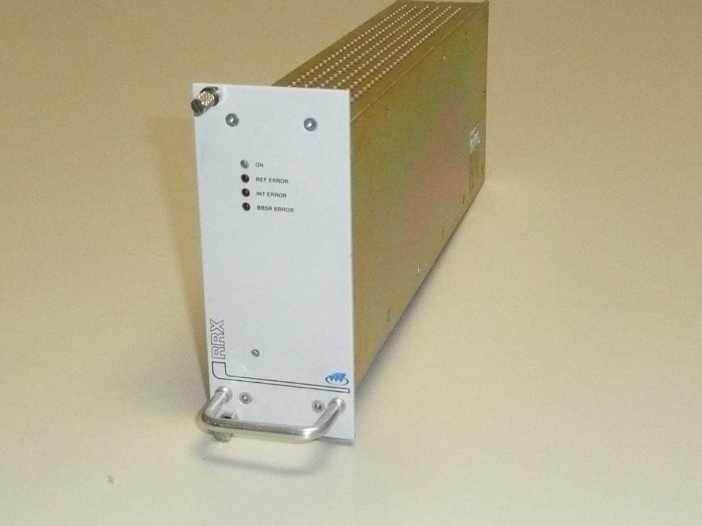
MI7-EZPRO25RF
Apr 06, 2008EzPro P-25 Base Station radio/repeater
Equipment Class
TNB - Licensed Non-Broadcast Station Transmitter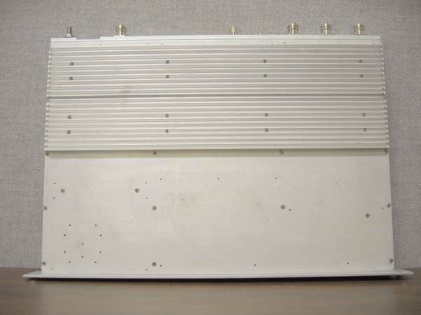
MI7-B64850D25
Jun 06, 2007Base Station for Mobile Data System
Equipment Class
TNB - Licensed Non-Broadcast Station Transmitter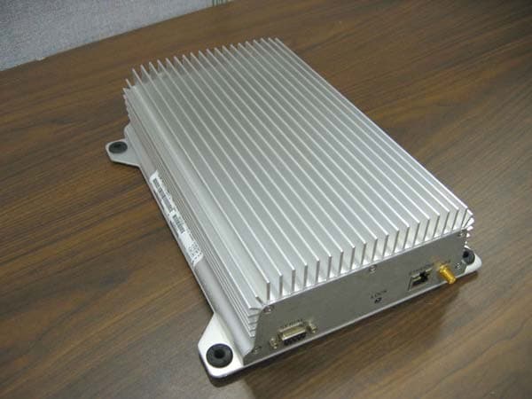
MI7-M64780D25
May 14, 2007High Speed Mobile Radio
Equipment Class
TNB - Licensed Non-Broadcast Station Transmitter
MI7-M64800D25
Sep 14, 2006High Speed Mobile Radio
Equipment Class
TNB - Licensed Non-Broadcast Station Transmitter