MKFARI0910MOTORCYCLE ALARM SYSTEM
Kenwo Industries Limited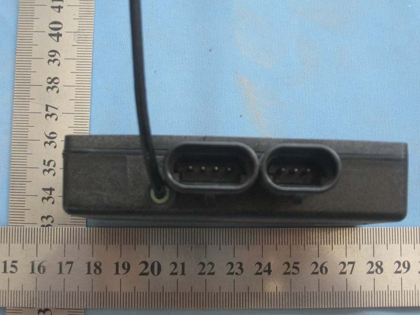
Click to zoom
Application Details
- Equipment Class
- PCB - PCS Licensed Transmitter
- Date of Grant
- Sep 08, 2010
- Application Purpose
- Original Equipment
- Date of Application
- Sep 08, 2010
- Equipment Note
- MOTORCYCLE ALARM SYSTEM
- Frequency Range
- 1850.20000000 - 1909.80000000
- Company
- Kenwo Industries Limited
- Country
- Hong Kong
Documents & Files
Document Text
Text extracted from the exhibit documents filed with the FCC. Open a document above to read the original.
Users Manual
60 Controls and Indicators NOTES HARLEY-DAVIDSON SMART SECURITYSYSTEMComponentsThe Harley-Davidson Smart Security System (H-DSSS) con-sists of a Hands-Free Security Module (HFSM) and a hands-free antenna mounted on the motorcycle, and a hands-freeFob carried by the rider/passenger. After parking the motorcycle, turn the ignition key to OFF andthe Smart Security System will automatically arm within five seconds. While armed, the starter and ignition are disabledand the rider may leave the motorcycle knowing that the modulewill activate an alarm if someone tampers with the ignition orattempts to move the motorcycle.If the fob is present, the module will automatically disarm when the ignition key is turned to IGNITION or ACCESS. NOTE Do not relocate the module or the antenna on the motorcycle. OptionsSeveral options are available for the Harley-Davidson SmartSecurity System from the Harley-Davidson Genuine MotorAccessories and Motor Parts catalog. Options include:• Smart Siren and Smart Siren II. • Security Pager and Security Pager Receiver II. • Replacement Fobs. See a Harley-Davidson dealer for details.ANTITHEFT SYSTEMOperationThe motorcycle is equipped with a GPS antitheft system. Whensubscribed to a monitoring service, the antitheft feature canbe used to assist in the recovery of your motorcycle.The antitheft system monitors the location of the motorcycleusing signals from GPS satellites. The location of the motor-cycle is periodically communicated to your monitoring servicecenter.When a theft event is reported, the monitoring service centercan track the location of the motorcycle, and can send a remotealarm signal to the antitheft system causing the turn signals toflash and siren to sound. The motorcycle will be unable to starton the next startup attempt and will be unable to start until the 61 HANDS-FREE SECURITY MODULE service provider resets the system. For safety reasons, themotorcycle will not shut off when it is already running.The antitheft system works together with the features of theHands Free Security System. When a theft event occurs whilethe security system is armed, the system will operate asdescribed in HANDS-FREE SECURITY MODULE, Harley-Davidson Smart Security System.Contact your service provider for additional details on monit-oring services.TamperingIf the tracking module or the HFSM is tampered with orremoved from the vehicle, the motorcycle cannot be started(the starter and ignition circuits may be disabled). The trackingmodule siren will sound if the security system is armed.The tracking module will continue to operate for a period oftime while the module is removed from the motorcycle or thebattery is disconnected.ActivationThe antitheft module is installed and ready for service from thefactory.You must subscribe with a DENATRAN certified serviceprovider for GPS monitoring and remote alarm services. To deactivate service, simply terminate your subscription withthe monitoring service provider.Reporting an EventIf the motorcycle is stolen, immediately report it to the lawenforcement authorities at the location where the theft occurred.Provide the vehicle identification number (VIN) and proof ofownership.Indicate that the motorcycle is equipped with an antithefttracking module, and provide the name of the monitoring ser-vice provider. Contact your service provider and indicate anyfurther details as needed.Change of Address or OwnershipWhen moving to a new residence or when buying or selling amotorcycle equipped with an antitheft system, contact thedepartment of transit to update the registration on the vehicleand contact the monitoring service provider to activate/deac-tivate monitoring services as needed.FCC REGULATIONSFCC ID: L2C0027TR IC ID: 3432A-0027TRFCC ID: L2C0028TR IC ID: 3432A-0028TR 62 Hands-Free Security Module
Cover Letter(s)
Kenwo Industries Limited Unit 1-2, 7/F, Block A, Hi-Tech Ind Ctr 5 Park Tin Par Street Tsuen Wan, Hong Kong Authority letter Date: 2010-07-29 FCC ID: MKFARI0910 To whom it may concern: We,the undersigned,hereby authorize WORLD STANDARDIZATION CERTIFICATION & TESTING CO., LTD.(WSCT)of Shenzhen to act on our behalf, as our agent, in the following matters related to the CE approval of our products: report submittal, related correspondence, the signing of all documents relating to these matters, and any other lawful activity necessary to obtain such certification. Any act carried out by WSCT within the scope of this authorization shall have the same effects as our own. This authorization shall expire 6 months from original date. If you have any questions regarding the authorization, please don’t hesitate to contact us. Thank you. Sincerely: Yick Keung Lau Unit 1-2, 7/F, Block A, Hi-Tech Ind Ctr 5 Park Tin Par Street Tsuen Wan, Hong Kong Authority letter Tel: (852)2415 3286 Fax: (852)2415 3799
External Photos
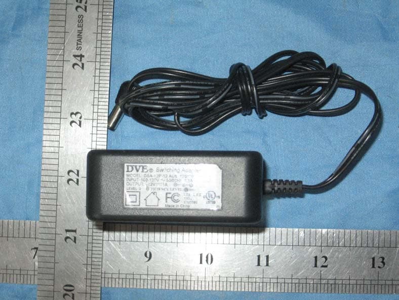
FCC ID: MKFARI0910 EXTERIOR PHOTOGRAPHS
ID Label/Location Info
FCC ID: MKFARI0910 Label: Labellocation FCC ID: MKFARI0910 This device complies with Part 15 of the FCC Rules. Operation is subject to the following two conditions: (1)this device may not cause harmful interference, and (2)this device must accept any interference received, including interference that may cause undesired operation. MADE IN CHINA
Internal Photos
FCC ID: MKFARI0910 INTERIOR PHOTOGRAPHY
Operational Description
Motorcycle Alarm System Electronic Circuit Description Product Introduction: This is an anti‐theft system that has tracking feature composed of GSM communication function and GPS function. Power Supply Voltage: DC12.6V Frequency range: 824—895MHZ、1850‐1910MHZ Circuit description: 1. The switching power is composed of U4 and related components, on/off is controlled by MCU (U8). U15 is a regulator IC and provides a stable voltage of 3.8VDC power to the GSM module. 2. U14 is a regulator IC that provides a stable 5VDC power for constant current charging controlled by MCU (U8). The constant current circuit consists of Q4 and related components that provides the steady charging voltage for the back‐up battery (BAT1 3.6V). 3. The DC‐DC power supply circuit consists of U5 and related component, on/off is controlled by MCU (U8). When normal power supply ( 12.6V ) is disconnected, this DC‐DC circuit will get power from the back‐up battery and supply power to the MCU (U8) and the alarm power amplifier output circuit. The Q10 and Q11 will be the power switches when it’s the transport mode. 4. Q6,Q7,Q9 and the periphery component is the power switch that for the back‐up battery (BAT1 3.6V), controlled by MCU (U8). 5. U2 and the periphery component is the left/right light drive circuit, controlled by MCU (U8). 6. Q5 and the periphery component is the relay drive circuit, controlled by MCU (U8). 7. Q1 is the steering circuit that controls on/off of the GSM module (U7) and controlled by MCU (U8). 8. Q8 is the reset circuit , controlled by MCU (U8). 9. U11 is the SIM IC, parallel connection with the SIM card holder. 10. U12, U6 and U9 are voltage stabilizer, they provide the stable DC power for the GPS module (U1) and the GPS antenna. 11. U1 is the GPS module, it receives the GPS signal and send out the GPS data to the MCU.. 12. U10 is a regulator IC, provides the steady working power 3.3V for the U8 (MCU). 13. U8(MCU)、U13(2.5V reset IC)、X1(32.768KHZ)、 X2(16.000MHZ) and the periphery components composing a powerful manage‐controlling circuit. 14. U13 is an external flash memory. 15. Q2 and T1 compose an alarm sound power amplifier. BZ1 is the Buzzer. 16. The pin 1 of the CON1 is an input pin for the VDD (12.6V) ; the pin 2 of the CON1 is an input pin for MCU (U8) wired control signal; the pin 3 of the CON1 is the GND.
Test Report
FCC ID: MKFARI0910 Page 1 FCC ID TEST REPORT for Motorcycle Alarm System MODEL: 68958-07BR FCC ID: MKFARI0910 Test Report Number: WSCT10060184E Issued Date:August 26 , 2010 Issued for Kenwo Industries Limited Unit 1-2, 7/F, Block A, Hi-Tech Ind Ctr 5 Park Tin Par Street Tsuen Wan,Hong Kong Issued By: WORLD STANDARDIZATION CERTIFICATION & TESTING CO., LTD. 1-2/F, DaChong Science&Technology Building, No.28 of Tonggu Road, Nanshan District, ShenZhen.PRC TEL: +86-755-26996192 FAX: +86-755-26996253 Note: This report shall not be reproduced except in full, without the written approval of World Standardization Certification& Testing CO., LTD. This document may be altered or revised by World Standardization Certification& Testing CO., LTD. personnel only, and shall be noted in the revision section of the document. The test results in the report only apply to the tested sample. Report reference No.:WSCT10060184E Issued:August 26, 2010 Revised:None FCC ID: MKFARI0910 Page 2 of 53 This report shall not be reproduced except in full, without the written approval of World Standardization Certification & Testing CO., LTD. Revision History Of Report Rev. Issue No. Revisions Effect Page Revised By 00 WSCT10060184E Initial Issue ALL Kallen Wang Report reference No.:WSCT10060184E Issued:August 26, 2010 Revised:None FCC ID: MKFARI0910 Page 3 of 53 This report shall not be reproduced except in full, without the written approval of World Standardization Certification & Testing CO., LTD. TABLE OF CONTENTS 1 TEST CERTIFICATION ............................................................................... 4 2 TEST RESULT SUMMARY ............................................................................ 5 3 EUT DESCRIPTION ............................................................................... 6 4 FACILITIES AND ACCREDITATIONS ................................................................ 7 5 TEST EQUIPMENT ...................................................................... 8 6 RF EXPOSURE ........................................................................................ 10 6.1 Applicable standards......................................................................... 10 6.2 Test Data............................................................................ 10 7 MODULATION CHARACTERISTIC ............................................................... 11 7.1 Applicable standards............................................................................ 11 8 RF OUTPUT POWER ............................................................................... 12 8.1 Applicable standards ........................................................................... 12 8.2 Test procedure ...................................................................................... 12 8.3 Test Data ................................................................................ ...... 12 9 Occupied Bandwidth............................................................................... 22 9.1 Applicable standards .............................................................................. 22 9.2 Test procedure ................................................................................ 22 9.3 Test Data ................................................................................... ...... 22 10 SPURIOUS EMISSIONS AT ANTENNA TERMINALS .................................................... 26 10.1 Applicable standards ............................................................ 26 10.2 Test procedure ................................................................................... 26 10.3 Test Data ....................................................................... ...... 26 11 SPURIOUS RADIATED EMISSIONS ................................................................ 38 11.1 Applicable standards .............................................................................. 38 11.2 Test procedure ......................................................................................... 38 11.3 Test Data ................................................................................ ...... 39 12 BAND EDGES ........................................................................................ 41 12.1 Applicable standards ........................................................................... 41 12.2 Test procedure ................................................................................... 41 12.3 Test Data ................................................................................... ...... 41 13 FREQUENCY STABILITY... ........................................................ 50 13.1 Applicable standards .............................................................................. 50 13.2 Test procedure ...................................................................................... 50 13.3 Test Data ................................................................................ ...... 50 Report reference No.:WSCT10060184E Issued:August 26, 2010 Revised:None FCC ID: MKFARI0910 Page 4 of 53 This report shall not be reproduced except in full, without the written approval of World Standardization Certification & Testing CO., LTD. 1 TEST CERTIFICATION Product: Motorcycle Alarm System Model: 68958-07BR Applicant: Kenwo Industries Limited Unit 1-2, 7/F, Block A, Hi-Tech Ind Ctr 5 Park Tin Par Street Tsuen Wan,Hong Kong Factory: Kenwo manufacturing Factory Linwu Industrial Area,Junzibu,GuanLan, Baoan ,Shenzhen, China Trade Mark: N/A Tested: June 09~August 26, 2010 Test Voltage: DC 12.6 V Applicable Standards: FCC Part 2 Subpart J, FCC Part 22 Subpart H, FCC Part 24 Subpart E, TIA/EIA 603-C,ANSI C63.4:2003 Deviation from Applicable Standard None The above equipment has been tested by World Standardization Certification & Testing Co., Ltd., and found compliance with the requirements set forth in the technical standards mentioned above. The results of testing in this report apply onl…
Text truncated - open the document above for the full version.
Test Setup Photos
FCC ID: MKFARI0910 TEST SETUP PHOTOGRAPHY Radiation Emission:
Contact Information
Applicant
Yick Keung Lau(Managing Director)
Test Firm
WorldStandardizationCertification&Testing CO.,LTDHuang Di
Technical Specifications
| # | Rule Parts | Frequency Range | Power Output | Emission | Tolerance |
|---|---|---|---|---|---|
| 2 | 24E | 1.85 GHz - 1.91 GHz | 953.00 mW | 319KGXW | 0.0165 ppm |
Other Applications from Kenwo Industries Limited
MKFARI59
May 13, 2010TRAILER MONITORING SYSTEM
Equipment Class
DSR - Part 15 Remote Control/Security Device Transceiver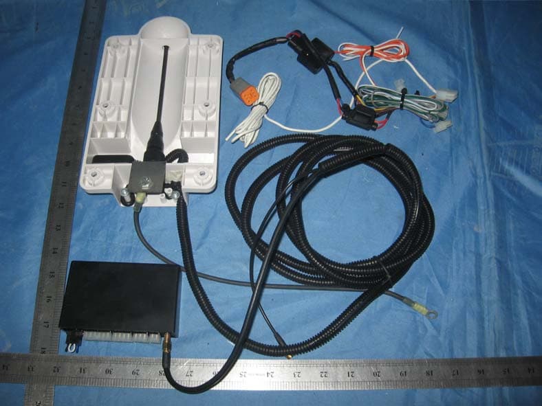
MKFARI57
May 11, 2010TRAILER MONITORING SYSTEM
Equipment Class
CYY - Communications Receiver used w/Pt 15 Transmitter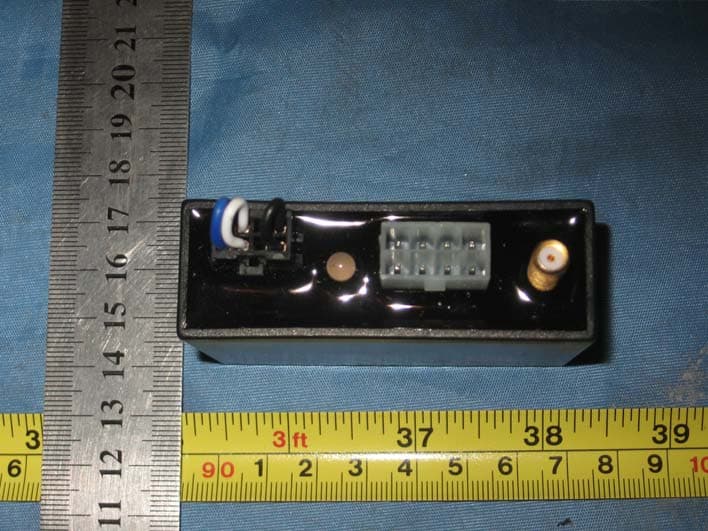
MKFARI61
May 05, 2010TRAILER MONITORING SYSTEM RX
Equipment Class
CYY - Communications Receiver used w/Pt 15 Transmitter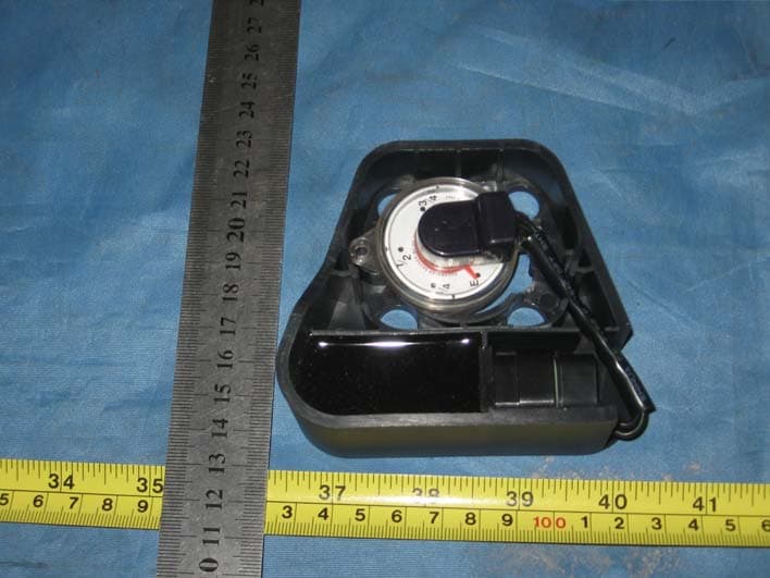
MKFARI62
May 02, 2010TRAILER MONITORING SYSTEM
Equipment Class
DSC - Part 15 Security/Remote Control Transmitter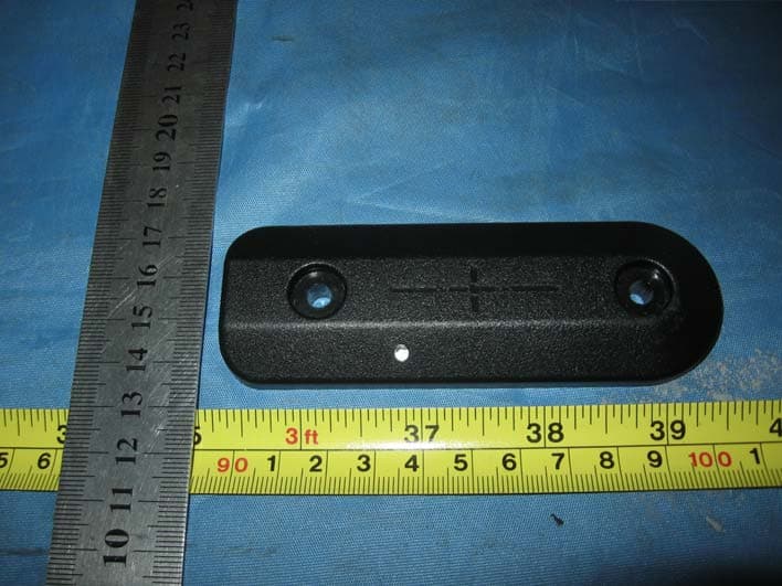
MKFARI56
Apr 27, 2010TRAILER MONITORING SYSTEM
Equipment Class
DSC - Part 15 Security/Remote Control Transmitter