MKFARI62TRAILER MONITORING SYSTEM
Kenwo Industries Limited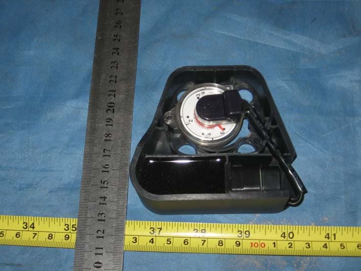
Click to zoom
Application Details
- Equipment Class
- DSC - Part 15 Security/Remote Control Transmitter
- Date of Grant
- May 02, 2010
- Application Purpose
- Original Equipment
- Date of Application
- Apr 29, 2010
- Equipment Note
- TRAILER MONITORING SYSTEM
- Frequency Range
- 315.00000000 - 315.00000000
- Company
- Kenwo Industries Limited
- Country
- Hong Kong
Documents & Files
Document Text
Text extracted from the exhibit documents filed with the FCC. Open a document above to read the original.
Users Manual
TRMS-RFS-FS006 Use guidelines This product is used in refrigeration auto after-sales, It consists of a fuel testing dials and corresponding fuel level transmitter, It can detect the fuel through wireless transmission to the receiver, Its value will receive fuel in panels show corresponding fuel, Users can to monitoring engine fuel level of time, Ensure the engine fuel run when needed When installation remove the wire fuel header and fixed screw, Then put the plug in the belt fuel instructions headers, Then put the plug in the belt fuel instructions headers, Matched with learn ID: After install this product, it must match with the learn ID of the new Host, Then they can communicate each other, In the first study, please change the receiving host into learning mode; please refer TRMS-400 use guidelines, Then insert the three pin plug fuel headers to fuel detection transmitter, In 30 seconds to send a fuel ID to TRMS – 400 learn, And the LED of the transmitter will flash, TRMS - 400 receiver will save the transmitter after receiving the ID of RFS-FS006, If fuel in receiving scope change above 5%, fuel hair and testing machine will launch signal, TRMS - 400 received is output corresponding fuel to display panel, In order to monitor the real-time state of the fule level. If RFS - DS002 state changes and its lights flashing very dark or not, It means low batteries, Please change it, And please reconnect with host learn code This device complies with Part 15 of the FCC rules. Operation is subject to the following two conditions: (1) this device may not cause harmful interference, and (2)this devices must accept any interference received, including interference that may cause undesired operation. Caution content: changes or modifications not expressly approved by the party responsible for compliance could void the user's authority to operate the equipment
Cover Letter(s)
Kenwo Industries Limited Unit 1-2, 7/F, Block A, Hi-Tech Ind Ctr 5 Park Tin Par Street Tsuen Wan, Hong Kong Authority letter Date: 2010-04-20 FCC ID: MKFARI62 American Telecommunications Certification Body, Inc. 6731 Whittier Avenue Suite C110 McLean, VA 22101 To Whom It May Concern: WORLD STANDARDIZATION CERTIFICATION & TESTING CO., LTD. Laboratory is authorized to act on our behalf, until otherwise notified, for applications to American Telecommunications Certification Body, Inc. (ATCB). We certify that we are not subject to denial of federal benefits, that includes FCC benefits, pursuant to Section 5301 of the Anti-Drug Abuse Act of 1988, U.S.C. 862. Further, no party, as defined in 47 CFR 1.2002 (b) to the application is subject to denial of federal benefits, that includes FCC benefits. Thank you. Regards, Yick Keung Lau Unit 1-2, 7/F, Block A, Hi-Tech Ind Ctr 5 Park Tin Par Street Tsuen Wan, Hong Kong Authority letter Tel: (852)2415 3286 Fax: (852)2415 3799
Cover Letter(s)
Kenwo Industries Limited Unit 1-2, 7/F, Block A, Hi-Tech Ind Ctr 5 Park Tin Par Street Tsuen Wan, Hong Kong Confidentiality Date: 2010-04-20 FCC ID: MKFARI62 American Telecommunications Certification Body, Inc. 6731 Whittier Avenue Suite C110 McLean, VA 22101 Request for Confidentiality Pursuant to Sections 0.457 and 0.459 of the commissions rules, we hereby request that the following documents be held confidential: (List here the documents for which you are seeking confidentiality – for example ...) • Schematics • Block diagram These materials contain trade secrets and proprietary information and are not customarily released to the public. The public disclosure of this information might be harmful to the company and provide unjustified benefits to our competitors. Thank you. Regards, Yick Keung Lau Unit 1-2, 7/F, Block A, Hi-Tech Ind Ctr 5 Park Tin Par Street Tsuen Wan, Hong Kong Authority letter Tel: (852)2415 3286 Fax: (852)2415 3799
External Photos
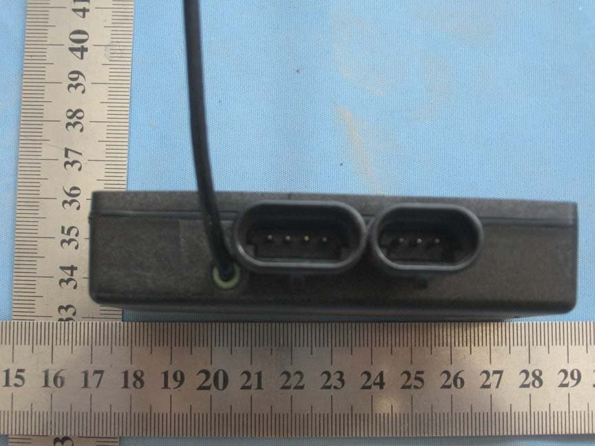
FCC ID: MKFARI62 EXTERIOR PHOTOGRAPHS
ID Label/Location Info
FCC ID: MKFARI62 Lable location: Lable: PART # : RFS- FS006 MFR S/N: 0000000 FCC ID:MKFARI62 Made in China
Internal Photos
FCC ID: MKFARI62 INTERIOR PHOTOGRAPHY
Operational Description
Technical Description: TRMS-RFS-006 MCU section: The unit contains a powerful MCU (micro-controller) U2, Which controls all the functions of the whole unit, a TX section send data signals to receiver.. Sampling section: Sampling circuit is consist of Q1,Q2 R1~R5 and CW1, Rheostat of CW1 locating on the head of the fuel meter, It's resistance would changed if the fuel volume varies. The MCU outputs a pulse every second to turns Q2 on, width of the pulse is 250us; Then , the MCU samples A,B respectively and figure out resistance according the sampled voltage, by using value of resistance, The MCU will soon look up the fuel volume which contains in it's memory, fuel volume was divided into 20 degrees, if there more than one degree variety was detected in one minute, A data pulse will be outputted on 6th pin of the MCU in order to power the RF module, so that the information of fuel volume can be transmitted , emitting duration will come up to 200ms. Power control section: The RF power control module including Q3,Q4,R9,and R11, Power supply will be turned off to reduce power consumption while there is no emitting occurs, so cell battery can serve much more days. RF section: U1 and it’s relevant components forming the transmission circuit, during it’s power on, the transmission circuit emitting signals from MCU at 315MHz, and this 315MHz carrier wave is generated by quartz and U1’s inner circuit, C4, L3, C7 forming the antenna network. amplitude modulation
Test Report
FCC ID: MKFAR162 Page 1 FCC ID TEST REPORT for TRAILER MONITORING SYSTEM Trade Mark: N/A Model: TRMS-RFS-FS006 Test Report Number:WSCT10040109E Issued Date:April 30, 2010 Issued for Kenwo Industries Limited Unit 1-2, 7/F, Block A, Hi-Tech Ind Ctr 5 Park Tin Par Street Tsuen Wan,Hong Kong Issued by: WORLD STANDARDIZATION CERTIFICATION & TESTING CO., LTD. 1-2/F, DACHONG SCIENCE & TECHNOLOGY BUILDING NO.28 OF TONGGU ROAD, NANSHAN DISTRICT, SHENZHEN. PRC TEL: +86-755-26996192 FAX: +86-755-26996253 Note: This report shall not be reproduced except in full, without the written approval of World Standardization Certification& Testing CO., LTD. This document may be altered or revised by World Standardization Certification& Testing CO., LTD. personnel only, and shall be noted in the revision section of the document. The test results in the report only apply to the tested sample. Report reference No.:WSCT10040109E Issued: April 30, 2010 Revised:None TRF No.:FCC PART 15C-15.231/A0 Page 2 of 21 FCC ID: MKFAR162 This report shall not be reproduced except in full, without the written approval of World Standardization Certification & Testing CO., LTD. Revision History of report Rev. Issue No. Revisions Effect Page Revised By 00 WSCT10040109E Initial Issue ALL Kallen Wang Report reference No.:WSCT10040109E Issued: April 30, 2010 Revised:None TRF No.:FCC PART 15C-15.231/A0 Page 3 of 21 FCC ID: MKFAR162 This report shall not be reproduced except in full, without the written approval of World Standardization Certification & Testing CO., LTD. TABLE OF CONTENTS 1 TEST RESULT CERTIFICATION.............................................................................................. 4 2 TEST RESULT SUMMARY ....................................................................................................... 5 3 EUT DESCRIPTION................................................................................................................... 6 4 TEST METHODOLOGY.............................................................................................................7 4.1 DECISION OF FINAL TEST MODE......................................................................................................... 7 4.2 EUT SYSTEM OPERATION ................................................................................................................... 7 5 SETUP OF EQUIPMENT UNDER TEST ................................................................................... 8 5.1 DESCRIPTION OF SUPPORT UNITS ...................................................................................................8 5.2 CONFIGURATION OF SYSTEM UNDER TEST .................................................................................... 8 6 FACILITIES AND ACCREDITATIONS ..................................................................................... 9 6.1 FACILITIES ............................................................................................................................................. 9 6.2 ACCREDITATIONS................................................................................................................................. 9 6.3 MEASUREMENT UNCERTAINTY.......................................................................................................... 9 7 CONDUCTED EMISSION MEASUREMENT ......................................................................... 10 7.4 TEST SETUP ......................................................................................................................................... 11 7.5. TEST RESULTS.................................................................................................................................... 11 8 RADIATED EMISSION MEASUREMENT ............................................................................... 12 8.1 LIMITS OF RADIATED EMISSION MEASUREMENT........................................................................... 12 8.2 TEST INSTRUMENTS .......................................................................................................................... 13 8.3 TEST PROCEDURES........................................................................................................................... 13 8.4 TEST SETUP ........................................................................................................................................ 14 8.5 TEST RESULTS.................................................................................................................................... 15 9 20dB OCCUPIED BANDWIDTH MEASUEMENT ................................................................. 16 10 DWELL TIME MEASUREMENT .......................................................................................... 18 11. ANTENNA REQUIREMENT ............................................................................................... 21 Report reference No.:WSCT10040109E Issued: April 30, 2010 Revised:None TRF No.:FCC PART 15C-15.231/A0 Page 4 of 21 FCC ID: MKFAR162 This report shall not be reproduced except in full, without the written approval of World Standardization Certification & Testing CO., LTD. 1 TEST RESULT CERTIFICATION Product: TRAILER MONITORING SYSTEM Model: TRMS-RFS-FS006 Trade Mark: N/A Applicant: Kenwo Industries Limited Unit 1-2, 7/F, Block A, Hi-Tech Ind Ctr 5 Park Tin Par Street Tsuen Wan, Hong Kong Factory Kenwo Manufacturing Factory Linwu Industrial Area, Junzibu, Guanlan, Baoan, Shenzhen, China Tested Date: April 18~ April 20,2010 Test Voltage: DC 3.6V APPLICABLE STANDARDS STANDARD TEST RESULT FCC PART 15C No non-compliance noted ANSI C63.4: 2003 No non-compliance noted Note: 1. The test result judgment is decided by the limit of measurement standard 2. The information of measurement uncertainty is available upon the customer’s request. Deviation from Applicable Standard None The above equipment has been tested by World Standardization Certification & Testing Co., Ltd and found com…
Text truncated - open the document above for the full version.
Test Setup Photos
FCC ID: MKFARI62 TEST SETUP PHOTOGRAPHY Radiation Emission:
Contact Information
Applicant
Yick Keung Lau(Managing Director)
Technical Contact
WORLD STANDARDIZATION CERTIFICATION & TESTING CO.,Wu Kelly
[email protected]86-755-26996192
1-2/F, DaChong Science&Technology Building, · Shenzhen · China
Test Firm
WorldStandardizationCertification&Testing CO.,LTDHuang Di
Technical Specifications
| # | Rule Parts | Frequency Range | Power Output |
|---|---|---|---|
| 1 | 15.231(e) | 315 MHz - 315 MHz | - |
Other Applications from Kenwo Industries Limited
MKFARI0910
Sep 08, 2010MOTORCYCLE ALARM SYSTEM
Equipment Class
PCB - PCS Licensed Transmitter
MKFARI59
May 13, 2010TRAILER MONITORING SYSTEM
Equipment Class
DSR - Part 15 Remote Control/Security Device Transceiver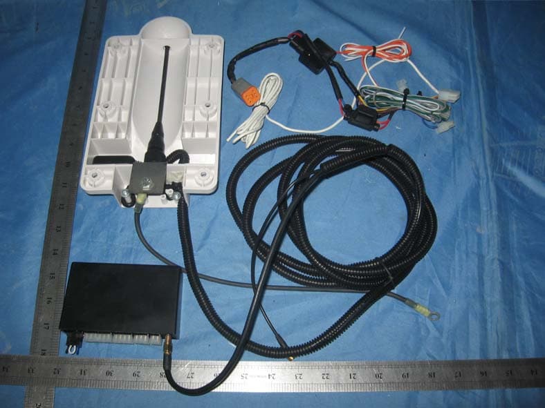
MKFARI57
May 11, 2010TRAILER MONITORING SYSTEM
Equipment Class
CYY - Communications Receiver used w/Pt 15 Transmitter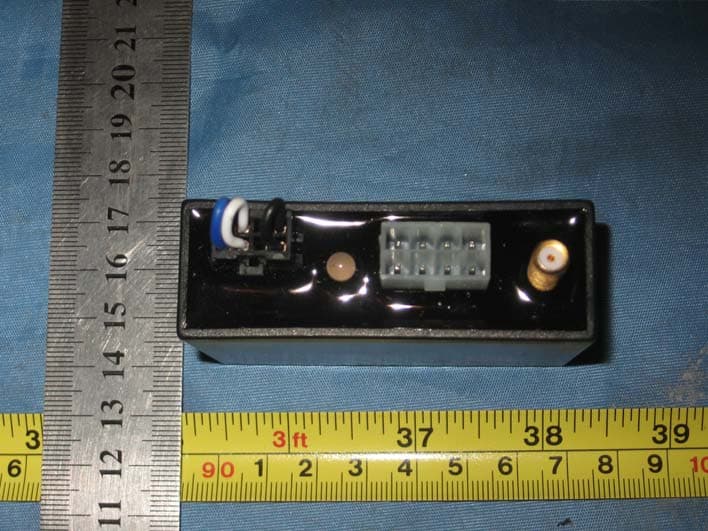
MKFARI61
May 05, 2010TRAILER MONITORING SYSTEM RX
Equipment Class
CYY - Communications Receiver used w/Pt 15 Transmitter
MKFARI56
Apr 27, 2010TRAILER MONITORING SYSTEM
Equipment Class
DSC - Part 15 Security/Remote Control Transmitter